Leaderboard


Popular Content
Showing content with the highest reputation on 01/23/22 in all areas
-
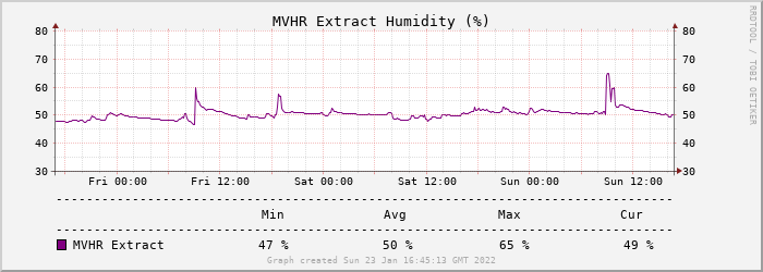
We moved into our new build mid-December 2017 in time to host an extended family Christmas. We are now over 4 years into living in our new home. We have lots of accumulated experience and made a few small tweaks. However, we are delighted about how the house has turned out, and we love living here. There were no material cock-ups, or regrets on design decisions, so we have probably fared a lot better than most new purchasers or self-builders. Maybe a general experiences post should be on the to do list, but what I want to focus on here, and a couple of follow-ups, is a general topic that others on the forum have asked about over the years: that is how our central heating system works in practice, and how I control it. The system as currently implemented is still largely the same as when I first commissioned it, that is a now 5 year-old RPi-based custom control system directly controlling the CH and DHW subsystems. This is a pretty minimal headless system running Node-RED, MySQL and MQTT client for control. The three material changes that I've made since moving in are: I have followed my son and son-in-law in using Home Assistant (HA) for general Home Automation. My server (an RPi4 in an Argon One case) uses an attached Zigbee gateway, and I have a lot of Zigbee devices around the house: switches, relays, light sensors, etc. and I do the typical home automation stuff with these. There are loads of YouTube videos and web articles covering how to implement HA, so please refer to these if you want to learn more. My HA installation includes an MQTT service for use as a connection hub for these IoT devices. I also have another RPi4 acting as an Internet-connected portal / Wireguard gateway/ file-server for caching video snippets from my PoE security cameras. Note that none of my IoT devices directly access the internet, and the only in-bound access into my LAN is via Wireguard tunnelled VPN, and my HTTPS-only blog. All other ports are blocked at the router. Before moving in, we assumed a target internal temperature of 20°C. In practice, we have found this too cold for our (fairly inactive OAP) preference and so we have settled on a minimum control threshold of 22.3°C. As you will see below, because we largely heat during the E7 off-peak window the actual room temperatures have a ~1°C cycle over the day, so the average temperature is about 22.8°C. This hike of 2.8°C increases the number of net heating days since my design heating calcs and the increased delta against external temperatures in turn increases our forecast heating requirement by roughly 18% over our initial 2017 heating estimate. Because our UFH is only in the ground-floor slab, we found that our upper floors were typically 1-2°C cooler than the ground floor in the winter months. We also need more than the 7 off-peak hours of heating in the coldest months, so I have added an electric oil-filled radiator on our 1st-floor landing; HA controls this through a Zigbee smart plug that also reports back on actual energy drawn during the on-time. HA uses MQTT to pass the actual daily energy draw back to the CH control system. This radiator provides enough upper-floor top-up heat, and does so using cheap rate electricity. Note that all servers are directly connected to my Ethernet switch, and the CH/DHW system has all of its critical sensors and output controls directly attached. It can continue to control the CH and DHW subsystems even if the HA system or Internet is offline. There is also no direct user interface to the system, with all logging data is exported to MQTT, and key CH/CHW set-points and configuration are imported likewise. This integration with MQTT, enables user interfacing to be done through the HA Lovelace interface. If there is sufficient interest I can do follow-up posts on some more of the "Boffins Corner" type details on these implementations, or if this turns out to be more of a discussion then it might be better to move this stuff to its own BC topic. However, for the rest of this post I want to focus on the algorithmic and control aspects of the heating system. In terms of inputs and outputs to the control system, these are: There are ~20 DS18B20 1-Wire attached digital thermometers used to instrument pretty much all aspects of the CH / DHW systems. Few are actively used in the control algorithms but were rather added for initial commission, design verification and health checking. Some are also used to monitor and to trip alarms; for example, there is a temperature sensor on the out and return feed for each UFH pipe loop. These were used to do the initial zone balancing. However, the average of the return feeds is used as a good estimate of the aggregate slab temperature. One of the temperature sensors is also embedded in the central hall stud wall to act as a measure of average internal house temperature. There are two flow sensors on the cold feed to my 2 SunAmp DHW storage units to monitor DHW use and to help automate during-day DHW boost. There are 4 240V/20A SSRs used to switch the power to my (2-off) SunAmps, my (1-off) Willis heater, and my (1-off) circulation pump. These and the rest of my 240V household system were wired up and Part P certified by my electrician. These SSRs are switched by a 5V 50mA digital input, and so can be driven from an RPi or similar. (I used a I²C attached MCP23008A multi-port driver to do this, as this can drive 5V 50mA digital inputs, but its input I²C side is compatible with RPi GPIO specs.) There are many ways to "skin this cat", but whichever you choose for your control implementation your system will need to control some 240V/12A devices and take some input temperature sensors. My preference was to directly attach all such critical sensors and outputs. My heating algorithm calculates a daily heating budget in kWh (each midnight) as a simple linear function of the delta between average local forecast temperature for the next 24 hrs and the average hall temperature for the previous 24 hrs. This budget is then adjusted by the following to give an overall daily target which is converted in minutes of Willis on time. heat input from the heater mentioned above. a simple linear function of the delta average hall temperature and the target set-point (currently 22.3°C). This is a feedback term to compensate for systematic over or under heating. I initially calculated the 4 coefficients of the two functions using my design heating calcs and an estimate of the thermal capacity of the interior house fabric within the warm space. After collecting the first year's actual day, I then did a regression fit based on logged actual data to replace the design estimates by empirical values. This was about a 10% adjustment, but to be quite honest the initial values gave quite stable control because of the feedback compensation. The control system runs in one of three modes: No heating is required. Up to 420 mins of heating is required. The start time is set so that heating ends at 7 AM, and the slab is continuously heated during this window. More than 420 mins of heating is required. 420 mins of heating is carried out in the off-peak window. On each hour from 8 AM to 10 PM, if the hall temperature is below the set-point (22.3°C), then an N-minute heating boost is applied, where N is calculated by dividing the surplus heating into the 1-hour heating slots remaining. Here are two history outputs from HA showing some of the logged results. The LH graph is the slab temperature over the last 7 days. The general saw-tooth is identical from my 3-D heat flow modelling discussed in my earlier topic, Modelling the "Chunk" Heating of a Passive Slab. The 7 hr off-peak heating raises overall slab temperature by ~4-5 °C; well within UFH design tolerances, and no need for any HW buffer tank: the slab is the buffer. The RH graph is the hall temperature. Note the days where on-hour boosts were needed. (Also note that the CH system only updates the MQTT temperature data half-hourly, hence the stepped curves.) So the approach is fairly simple, and the system works robustly. ? And here is a screenshot of my HA summary interface, which gives Jan the ability to control everything she needs from her mobile phone or tablet.2 points
-
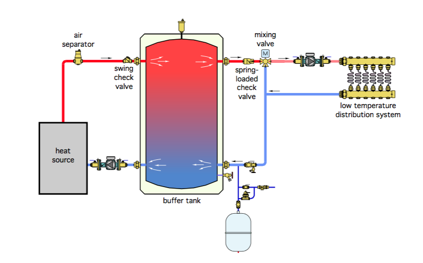
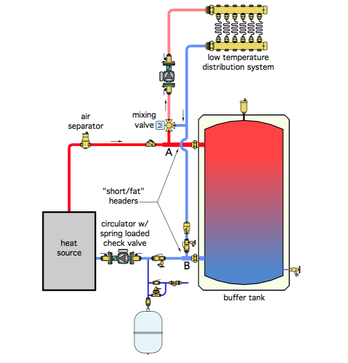
There are several ways to add a buffer.... https://blog.heatspring.com/2-pipe-versus-4-pipe-buffer-tank-configurations/ Figure 1 is what I have... In my case the room stats control the right hand side via a wiring centre. The wiring centre performs a logical OR function to control the manifold pump. The boiler/left hand side is controlled by a stat on the tank (and an optional timeclock). The left and right hand sides work independently from each other the only common thing is a Switched Fused Spur that powers both sides. However there are alternative ways. The two port system in Figure 4 is claimed to be more efficient but I've no experience of this approach.. The idea with thus approach is that flow from the boiler can go direct to the UFH. The buffer only takes "excess" water that the UFH doesn't need (for example if only one loop is calling for heat). I think this approach is better for ASHP systems as they have lower flow temperatures and this approach helps maintain the flow temperature.
 2 points
 -
Just did ours, maybe we were lucky but no issue with liquid screed (Longfloor) over insulation without fixings. As mentioned above, we also used dry sand to fill any voids beneath insulation - laid on concrete planks so plenty of undulations at joints and of course a bit cambered. Taped across all insulation sheet joints and a thin membrane as per normal process. @Thorfun that price looks v similar to mine per m2 - mine wasn't the cheapest I could find but was recommended and only ~5% more than cheapest so happy to pay a bit more for a bit of reassurance2 points
-
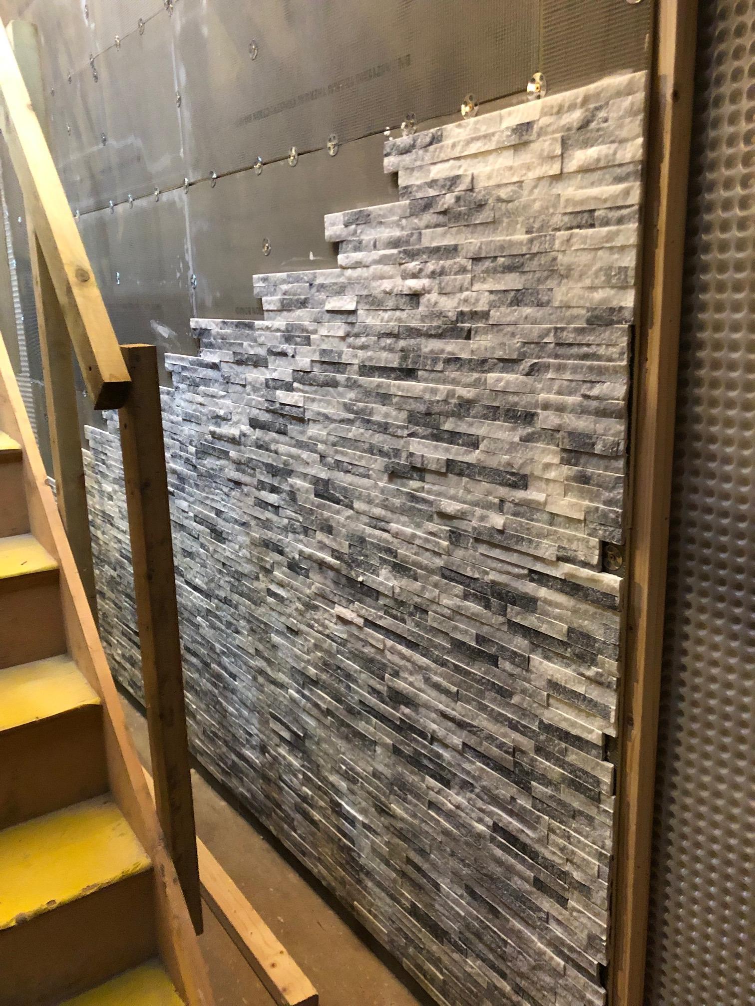
Started on this beast. 1500 tiles of pain. But starting to look like some wall from Game of Thrones " You Shall not pass!!"
 2 points
 -
It is But necessary I’ve been to tile two flo screed floors that haven’t been flat The only explanation is the screed getting under the insulation But the plastic seals the hole tight and there’s a slip membrane between the screed and the insulation So no chance of damp It normally takes two of us about an hour to do a 150m2 floor If your screed guys are responsible for installing the insulation They will probably do this with asking2 points
-
Just a dissenting perspective for anyone considering a Loxone route. You are looking at something like £10K +/- a factor of 2 for this route, and building, configuring and maintaining this type of system will either require a lot of expertise on your part or having to pay pretty high unit-rate Loxone certified engineer time to do this. Yes, this type of system might be sensible if you want a 100% automated house, but IMO if you are a more typical builder then an approach of only automating stuff where there is a good reason to do so means that you can sensibly look at options which will cost £100s rather than £1000s. If you have basic IT literacy and any basic programming skills then such more budget route is to use low cost server modules (such as PRi4s) and open-source components such are Home Assistant (HA) and Node RED. I spent 35 years in the IT industry from engineer through to CTO and there is nothing "cheap and cheerful" about these H/W and S/W components. The build quality and documentation are absolutely 1st rate. I use one RPi4 to run control my CH + DHW, another for HA doing general home automation, and a third as a gateway / general Docker host. I have around 50 Zigbee devices controlled by HA, plus a few Sonoff and Shelley devices running Tasmota and controlled through MQTT. The CH system has ~20 directly connected sensors and controls 4 directly connected power relays. This give me precise control of CH, DHW, various lights and external systems, etc. all for around £500.2 points
-
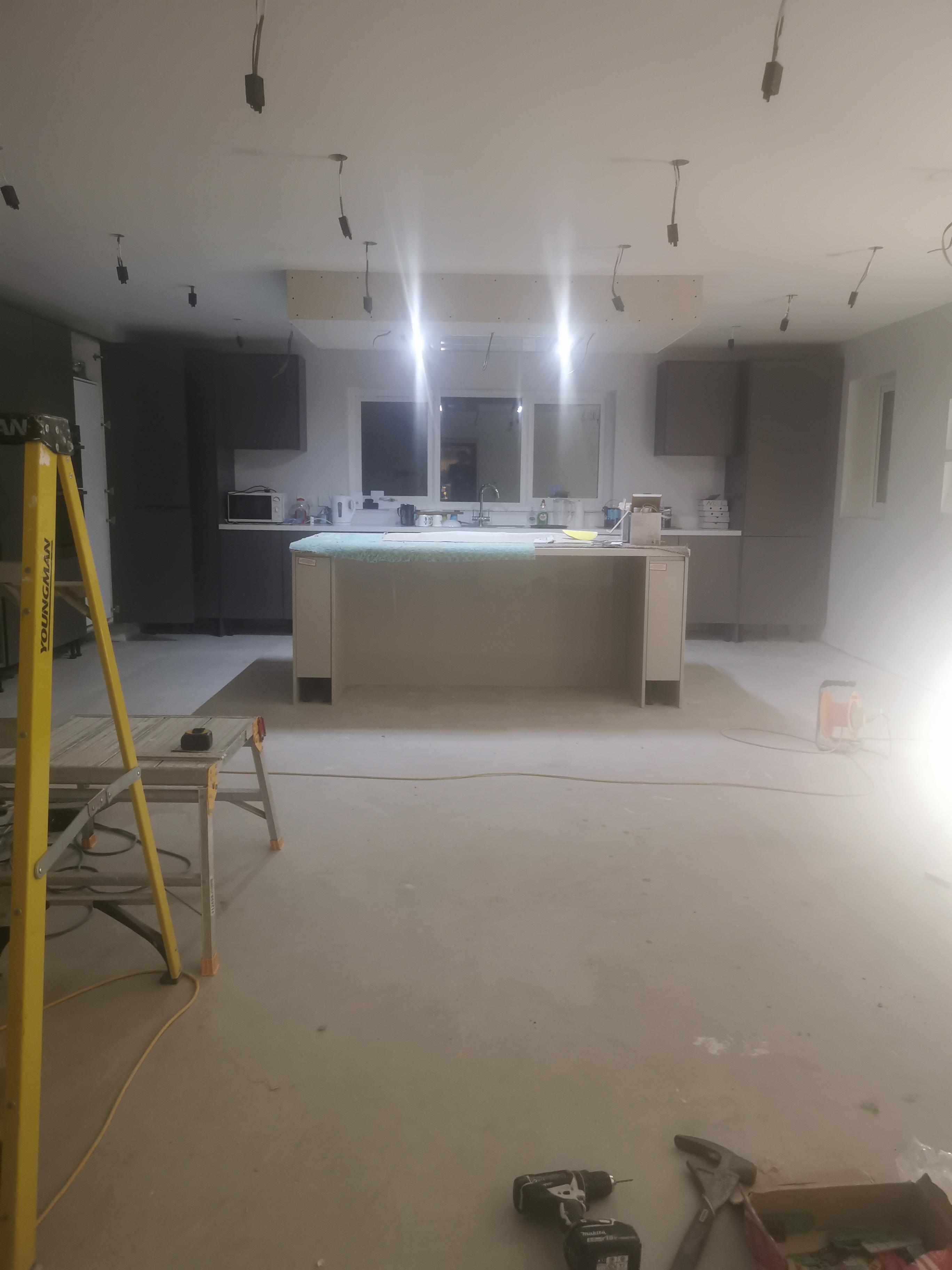
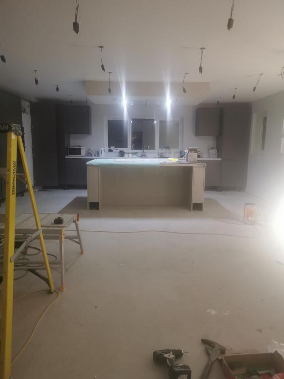
Hoping to get into the new house this week. The price increases have definitely hit the budget a bit, but not enough for it to hinder our determination to reach the finish line! A year since we got the foundations in and started putting up the panels the we had already made on site. Here's a glimpse of the kitchen, flooring has since been laid.
 1 point
 -
You can't staple to EPS, hence EPS at the bottom. If you are splitting use 50mm PIR minimum. Otherwise your staples will pull out.1 point
-
@Temp that is a really useful image - fig4 is my go to design (without the spring non return valves ..!) and is dead easy to do. @Soulfish not sure why you thing fig1 will take up less space ..? It’s easy to plumb and very simple. i would go with 100litre buffer - not expensive and all pretty standard so not much to choose between them tbh1 point
-
untilThis show will be held as a live event at the National Self Build & Renovation Centre in Swindon. NSBRC - Lydiard Fields, Great Western Way, Swindon SN5 8UB reception@nsbrc.co.uk / 0345 223 44 55 Pre-booked tickets are free: https://www.nsbrc.co.uk/whats-on/our-events/the-national-self-build-and-renovation-show/1 point
-
I am experimenting with Apple Homekit which no-one has mentioned yet. I have bought a Homepod mini, a smartplug, a bulb and a door opening sensor and got them all set up and working very well over Thread in the one room they are installed in. Bouyed by the impressive performance - ie instant and consistent activation I bought another bulb and a couple of further door sensors for our two outbuildings. The bulb - in an adjacent room - seems to be linked into the Thread mesh now and working. The two door sensors however appear to be too far away to join the mesh. So I will probably need to buy at least one ore smartplug to extend the mesh and I am hoping that will be enough to bring these sensors into the overall network. I am mainly interested atm in building a security system over Thread - it is looking promising so far - but down the line hope to instal Thread enabled smoke and heat dectectors and automated blinds.1 point
-
Just overlap it with a good run off membrane?♂️1 point
-
Who sized the GSHP at 12kW? If that is correct then an ASHP would also be 12kW. There are reported shortages of ASHP's as well so best of luck. some suggest the last gasp of the RHI is producing a demand peak to get systems in before that runs out.1 point
-
The membrane is your air tight layer, why are you wanting to seal it to the inner face of the plasterboard? Normally the plasterboard is just something that happens to be inside the sealed envelope of the house.1 point
-
Shame you didn’t soundproof the party wall at the time you extended.1 point
-
Hi all, Currently undertaking a self build in County Tyrone. At the first fix stage at the minute and have been as hands on as possible. Build wise the house is a 2900sq ft 2 storey. Insulated to an ok standard (150mm pumped cavity, 150mm pir floor) mvhr and ufh down and rads up. This place has been a great resource so far and just wanted to introduce myself.1 point
-
Small hole or big hole is a hole - I'd cut square pieces of airtight tape, pull the membrane and seal it. Do you actually have to pull the membrane, or is it where you want it? On the Tescon video (as far as I remember) they do staple, the assumption is well attached is airtight. Tears, cuts - again tape.1 point
-
@TerryE I have similar to yours, Node-Red, MQTT, SQL etc. I use a Radio Spares Power Bank (RS7757508) as UPS for the two Pi 3's employed in the monitoring and control of the UFH and MVHR. The RS power banks are the only ones I could find that do not interupt the output if the supply fails. They will run the Pi's for more than four hours. One of the pi's is also a wireless AP which allows connection should a long power cut be on the cards. Most of our cuts (which we have a few of) are only a few seconds. Node Red has repalced all the functions of the provided MVHR controller as it is junk, a power cut needs a clock reset.. what!! + I have added temp sensors into each of the four pipes plus a Co2 sensor in the extract pipe.1 point
-
1 point
-
Yes the mass flow will be higher, but the temperature differences is fixed. So to clarify, less energy will be taken out of the 'block' of air that is passing through. The overall energy should be the same over time. Except the other temperature differences, between the liquid refrigerant and the expanded refrigerant gas, will also be lower overall. It is a horrible balancing act that these heat curved try to sort out.1 point
-
Have you a copy of the full test cert for the unit, rather than just the COP quoted in the manual? It has a bit more info on when defrosts are likely, the required compressor speeds etc I've attached it just in case you don't... do you see the water pump throttling back much? I'd opine that flow through the heat exchanger (and therefore deltaT across the unit) is going to have more of an effect than fan speed. But again, look in Fan configuration to see the compressor speed and fan speed limits per ambient temp. CE-iVT9 EN14825 64.181.20.04362.01 Rev.00 TR Performance Pages.pdf1 point
-
If you increase the airspeed though the unit, the temperature difference will be less, so less energy is taken out of the air. This is probably done because the heat exchanger (that thing that looks like a car radiator) is of fixed size, so if the air movement was too slow, it would freeze out the moisture from the air. It does increase noise though. I suspect with a decent inverter driven unit, there will be a factory default setting, that changes both the fan speed and the compressor speed. Slowing the compressor should reduce the power at any given temperature, or lower the maximum temperature for a given power. Without know the controller (and its internals, though I am going to meet some people that know about this shit), I suspect that there is not a great deal of interaction change between the fan and the compressor, probably more a case of setting minimum and maximum temperatures. By setting limits on the two scales, a power curve comes out naturally. May not always be best for the CoP, but if you can set it up without getting towards the extremes, the CoP should be close to where it is best. It is a real shame that not all controllers use a standard terminology, it would make setting up easier.1 point
-
Ours works perfectly - not a single false positive or negative in the years it's been in place. Rate of rise detection is the secret (>5% in 5 minutes works for me), not absolute threshold triggering. It's the perfect alternative to trying to train partners and kids!
 1 point
 -
It is all here: maybe not that simple. https://mechanicalboost.com/carnot-engine/ Basically the equation PV/T=C means that you can change the pressure (P), the volume (V) or the temperature (T) and you will end up with the same constant number (C). So the air that passes through the unit will be at constant pressure (over the short term) but may vary in temperature, so changing the volume means you can extract the same, more or less energy, from that air. Within the actual heat pump, the volume is fixed, so you can only change the pressure before and after the compressor (within quite tight limits), this changes the temperature because the rate of expansion and condensation (latent heat of vapourisation) is varied. So you have two things that affect the output, the amount of air that passes through the unit, and the pressure within the unit.1 point
-
doesn't a liquid screed surround the UFH pipes better as it 'flows' around and under them to fill all available gaps? I didn't think a sand and cement screed did this so it would/could leave pockets of air resulting in slightly poorer heat-up times for UFH? I could be talking b******s though. we're having a liquid screed in the basement for the ease of it all. 6m3 of Cemfloor is costing me £2200 all-in (based in the SE before @nod quotes his up'north prices ? ). seems very reasonable to me and I'm happy to pay for the quickness of install and drying. For the ground floor I'm still undecided as to which way to go and I guess I'm using the basement as a tester to see how the liquid screed works.1 point
-
Absolutely no problem with traditional On 150m2 floor you would be looking at 20 ton load of screed No chance of anything moving As a business I probably only tile five flow screed per year and have seen two lift in the past five years Flo is great for tiling But everything needs to be down tight Or as you say you will only get a fine covering on the pipes1 point
-
Very interesting. A few years ago I remember a discussion here where I mentioned my concern that flowscreed might end up as a thin concrete crust lacking support from the insulation below. My concern at the time was that if PIR compresses it does not rebound back to its original shape unlike a cheaper spongy insulation sheet. I now realise that concern can be mitigated by installing a thin starter insulation sheet using a more elastic insulation sheet below the main layer of PIR and/or using sand to fill dips in the base floor. Thinking about about a point I raised above I don't suppose leaving the UFH pipework filled with water creates enough weight to keep the insulation sheets pinned down? Ho-Hmm I am starting to consider a traditional sand/cement screed again in the hope the extra weight keeps the insulation snugly weighted down to the base floor. Having watched many screed insulation videos I do not recall seeing use of these knock in pins. Is this an example of the industry solving a new problem that has come to light as thinner flow screeds are used?1 point
-
Mandatory in Scotland, has to be bedroom.1 point
-
Indeed, I understand how the design works, the fact each FCU is a closed system per room makes it elegant in many ways, but just saying unless you already have someone lined up to install it that has done this before, don't be surprised when there's lots of head scratching at install time, and potential for screwups. Tbh the whole M&E install will need a lot of oversight, if you're heating guy is on it that great, or maybe he's just specing it extra complex to ensure he's retained for the duration, I can't tell. Btw I was distinctly underwhelmed by the MelCloud app, and if it can intelligently coordinate across controllers then it is doing so via the cloud so be aware your heating may go wild if the internet is down/server maintenance/they discontinue the service. Unfortunately the FTC6 only has one controller connection port, so it's WiFi *or* modbus control, the latter being far more appropriate for a real BMS brains to drive it via.1 point
-
are you starting to get a feel for what's required for self-building and project managing? you pretty much need to have decided windows, blinds, cladding, insulation levels (determines wall thickness), ventilation system (in case MVHR ducting needs to pass through steels or glulams) and I'm sure there are more BEFORE your architect draws up the plans!! each blind manufacturer may have a slightly different requirement for their cassettes which will need to be factored in to the architects drawings and if you're going for an all-in-one solution with blinds and windows then you need to have decided on the window manufacturer as well. (one area that takes a lot of research and time to get quotes as there are a lot out there and, according to posts on here, prices vary for the same manufacturer depending on the job). everything is affected by everything else and it's only later down the line do you realise how much a decision has a knock-on effect on other parts. eg. we wanted external blinds and chose the Warema ones. They required at least 80mm from the external side of the timber frame to sit in to and so we had to have 2 x 47mm x 47mm timber battens for our vertical timber cladding. this added a lot of cost to the battening as we went for a standard 140mm TF. if we'd gone for the 300mm twin-wall TF I presume we wouldn't have needed such big battens, or even a 190mm TF walls then it would be the same. so the one decision to have external blinds added more that we thought at the time. not that we regret the decision it's just one of those things I've learnt as we progress through our self-build journey! each decision has many unforeseen effects. don't let me put you off though, it is a lot of fun and we're enjoying the experience a lot.1 point
-
Exactly. The element gets red hot, about 600°C. So at that temperature it only needs to move 2 l/s to dissipate 1000W. For another extreme example, imagine (just got a moment) me on my indoor stationary bike. My body can't deal with overheating by more than a couple °C so even though I'm only putting out a couple hundred watts, I need a gale force strength fan to keep cool.1 point
-
That is only a ridge board at the top, so you WILL need to retain the "ceiling" height beams that span wall to wall. They stop the roof sagging and pushing the walls outwards. A structural engineer might be able to come up with a scheme where some are removed and some remain, but you would not want to try anything like that without professional input.1 point
-
That is a lot of holes in the first membrane.1 point
-
They are just a plastic stem with a round plastic disk on the top Drill a 8 mil hole through the insulation and into the floor avoiding the beams Then tap in I normally put five per sheet when fixing Ready-fix sell them by the 200 box1 point
-
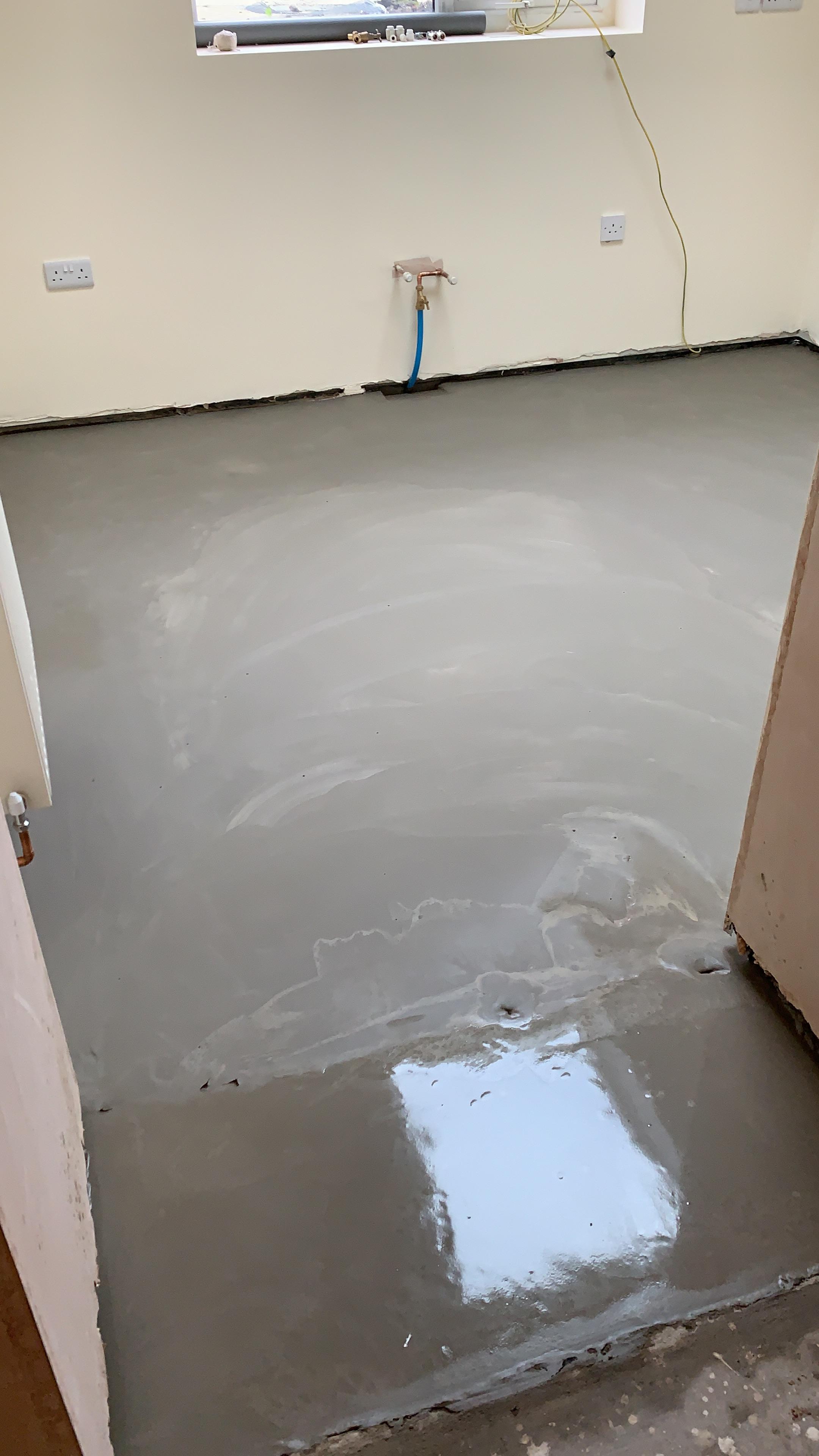
All done, thanks for the help, 2 small sink holes but minor issues to be filled later.
 1 point
 -
Knock in insulation fixings. T shaped plastic plug (like a big nail).1 point
-
If they “are” decorative then removing them will not change anything. are they connected to the walls or simply screwed or nailed to the timbers above? assuming they are not connected to the walls then removing is no problem and taking them out along with the ceiling will remove load from the trusses above so all ok.1 point
-
As always Steamy you are spot on! and elegant points made. For all, hope this helps the keen tecky. Take a timber floor joist, or a ruler at home. Support it at each end an apply a load in the middle. The ruler bends down so the top shortens and is in compression, the bottom stretches so is in tension. Masonry ( brick walls) are not good at resisting tension.. so if you add enough load to the top of the wall then the masonry never gets to the tension stage. Steamy is spot on.. this is the one of the basic basic concepts of prestressed concrete design. Steamy mentions what is called "buckling".. again correct. Put the ruler on it end and push down from the top. Suddenly it will give way.. this is a buckiling phenomena.. Euler circa 1700's the mathematiccian developed the theory behind this and is a fundamental principle underpinning what SE's do today. So yes Steamy, if you add to much load you risk buckling.1 point
-
Grian.. remember if you make something like this fly, enjoy building it and make some money then you got a leg up from BH.. so a small donation to BH would oil the works! I do think that if you have a local joiner on hand you could build a safe structure for holiday accomodation out of timber frame for not a massive outlay. You could almost have detachable cladding.. in effect the structural TF sits there and the outside cladding acts as a rain screen.. could be just recycled pallet wood at the very basic. As this is a temporary moveable structure not a house that you get a mortgage on that has a life expenctancy of 60 years you can afford to change the cladding and appearance if you wanted to suit you target market. I don't know where you are but the saw mills do some real rough but cheep timber off the outside of the log that can be used for cheep rain screening. You could use all sorts of material depending on what visual impression you want to give out.. I love this stuff. You could have great fun exploring what you can do and how you tailor the appearance to your intended holidaymaker market. My sister has a B & B on Tiree so the market there is split between commercial clients coming to serve the radio mast, fix the fridges in the coop ect and at the other end folk going for a holiday that want to stay in a nice place. Keep posting!1 point
-
Seem to remember learning about that. Cathetderal builders put heavy statues on the wall tops to help stabilizer the structure. Suppose it works the same a pre stressed concrete. Does it increase the risk of buckling if the mass is too great.1 point
-
Thanks @SteamyTea Much appreciated. Inverted roofs are something not much touched on on BH. More commonly you see them on larger refurbishment development and commercial stuff. They do have their issues but this for something like what @Grian wants to do on a limited budget while mitigating the financial risk, the constraints i.e moveable.. it could be an elegant, cost effective and environmentally positive solution. On the technical side I mentioned TF. You can increase the stiffness of a TF panel (thus better able to resist the sideways wind loading) by adding compression from above so the slabs perform this function.. it's all about getting the different elements of these small light weight buildings to do more than one job.. you look to get your pound of flesh out of them. Yes in a windy spot you will probably still need to tie down with cables for a bit of robustnees but the in the round I think this is worth a look at concept wise.1 point
-
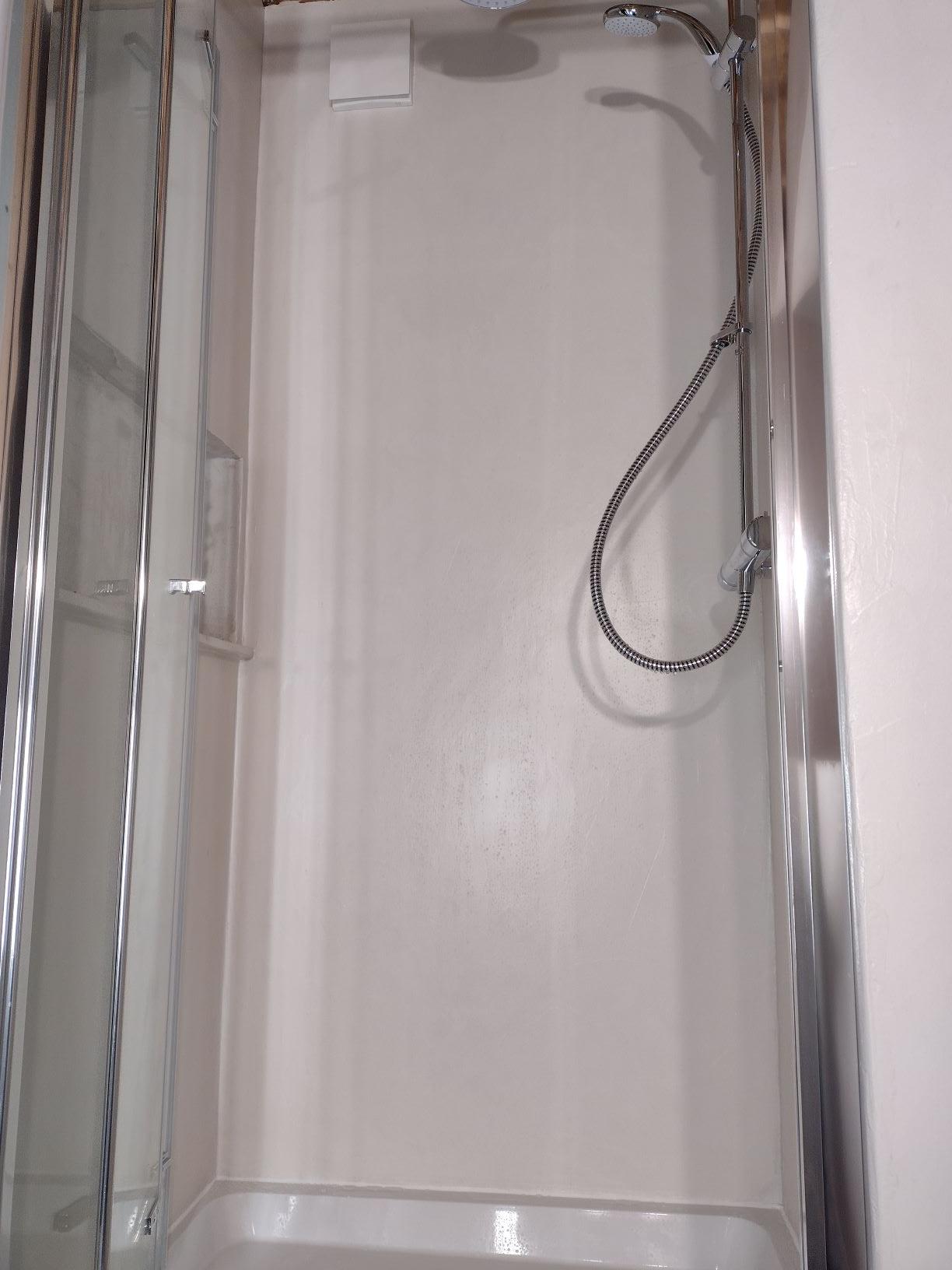
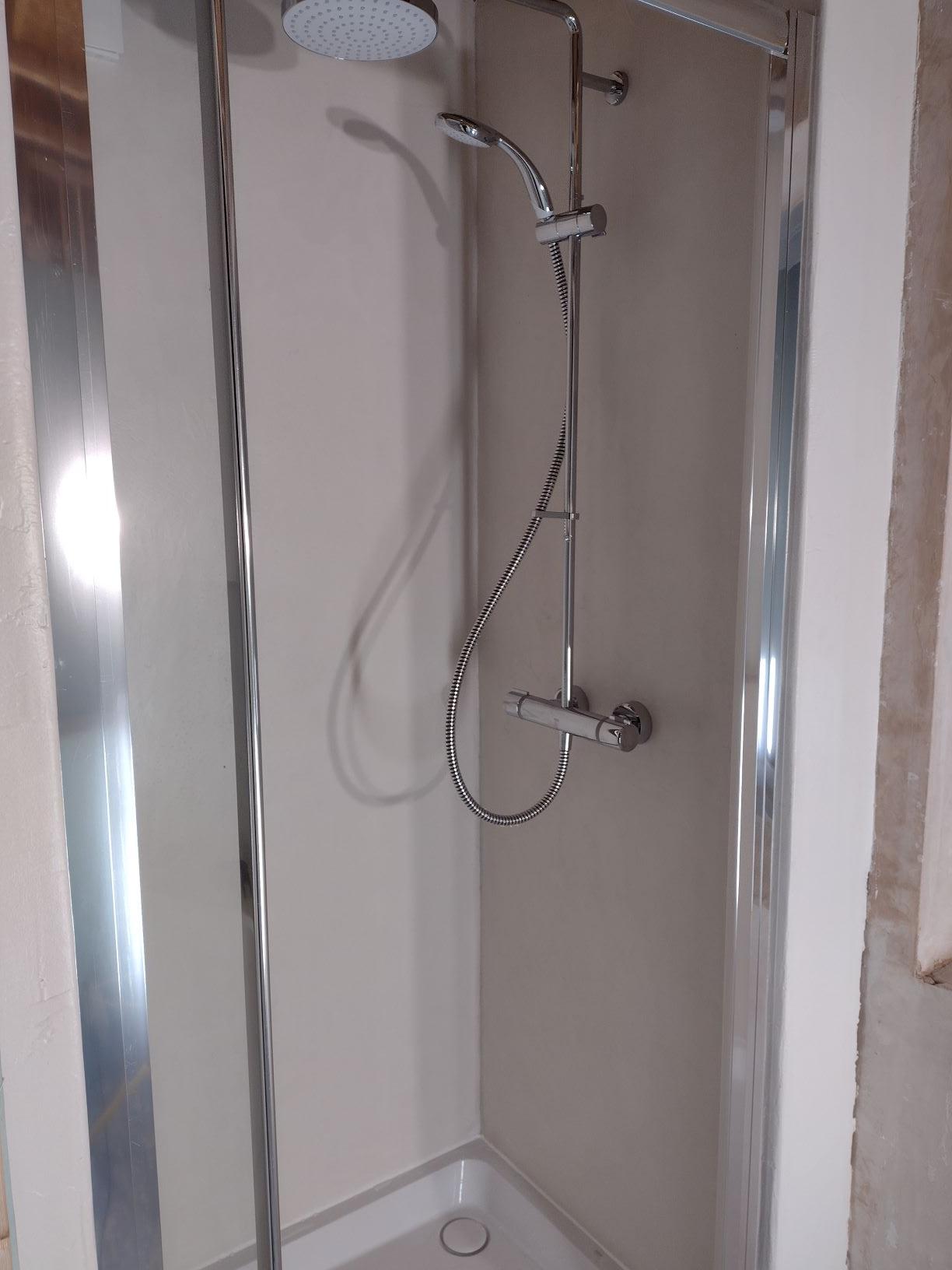
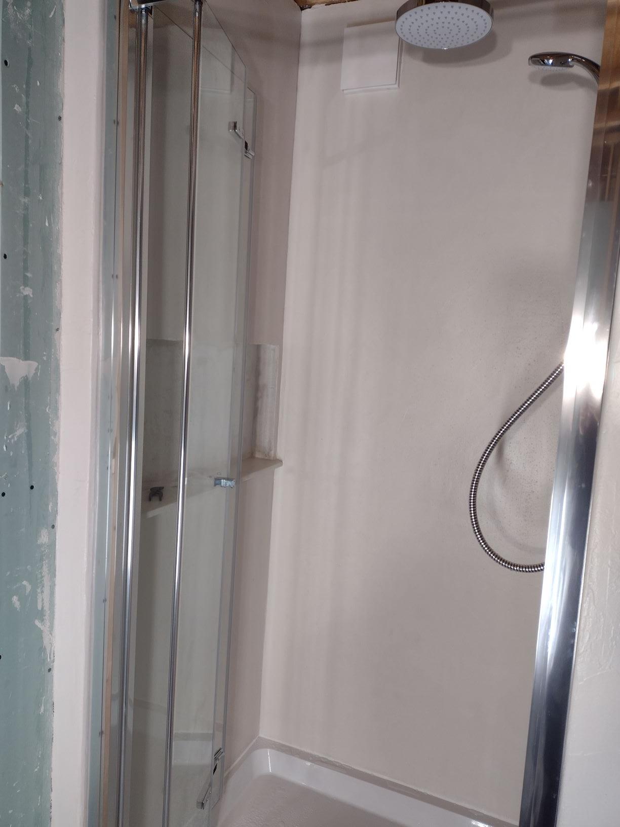
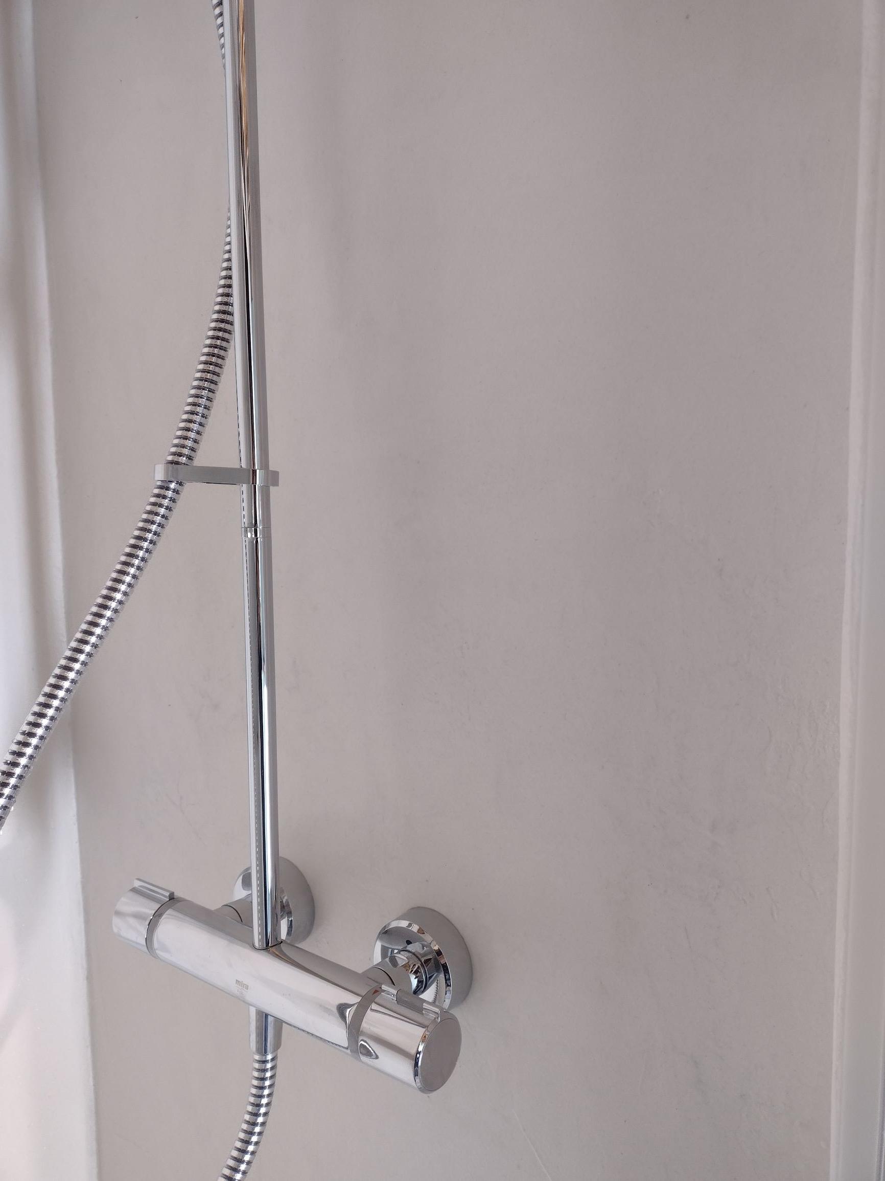
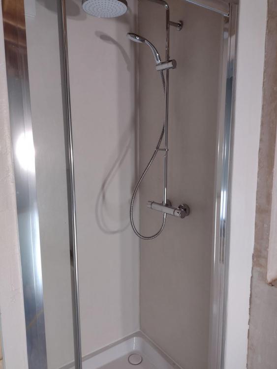
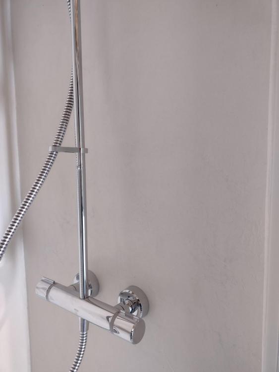
Okay, I've done the shower enclosure now. In total 4 coats of finishing resin since my last post, two coats each of a different type. Each coat sanded with 400 grit paper. I'm ever so slightly worried about the final coat as I was slightly short on hardener for this coat so I hoping it is hardy enough. However, if it isn't I can always get some of the same 2 part resin and re-coat. I've also put in the shower, shower door etc. but just waiting for tiles to put into the back and side of the built-in shelf. I'm very happy with how it's turned out. I like both the look and the colour (Montblanc White). Now we just have to see how it stands up to some abuse and I'll report back over time. Below are final photos where I've added a couple in the hope it shows the colour and texture in close up, but may not work. Hopefully this may help anybody looking at microcement in their shower.


 1 point
 -
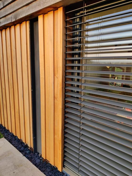
We used roughly the same detail. The timber frame company then supplied the frame with the recess made to measure. We actually made the recess slightly deeper and had the Roma blinds supplied with pre-fitted insulation on the rear of the blinds boxes (to make up for the loss of insulation in the window head). With the insulation in place the blinds are sat slightly further off the font of the windows, not that they would ever touch the window anyway. Our (Roma) blinds came pre-attached to the windows which made things so much easier and ensured that the blind head and length and everything was all supplied to work together ouf of the box. We also used a type of slat called CDL which i) is more stable in the wind ii) does a fairly good job of blacking out internally which is good for bedrooms. I found Roma fantastic: - They have a very comprehensive Kompendium with all technical details, max wind loads and options all explained in detail. - They have ton of options to customize things - They have an online CAD tool to design blinds, visualize in 3D, and then download in AutoCAD format to incorporate in your drawings. Only caveat with Roma is that they don't supply direct to U.K. I don't thnk. Ours were supplied with Gaulhoffer windows, after @Bitpipe did a stellar job of recommeding and demoing them to us ?1 point
-
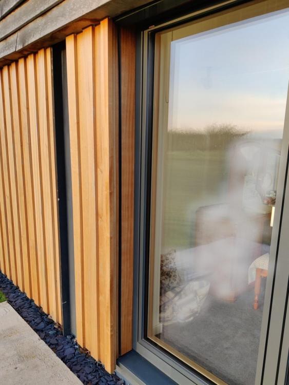
My installation is external to the wall structure, but within the timber cladding. You can see on Thorfun's install, it's sculpted in to the structure, and more efficient for overall wall width, but requires more of a local compromise on insulation thickness. The cladding details in my previous message were an early study before actual cladding sizes and windows were agreed. The final install did a better job of integrating the side channels and getting a bit more insulation against the frame, behind the cladding. I've never had any issues with the blinds touching the windows. They do get raised if there's a "blust" of wind over 36mph, and up to that speed they're surprisingly robust, even on the 5m spans on some of my larger windows. You can have versions that run on tensioned wires, that span top to bottom, and you can align these to the vertical mullions on the window, but I wanted as little of the blinds noticeable when raised as possible.
 1 point
 -
+1, you only replaced/repaired the existing path, not hard standing. Play hardball and let them prove otherwise, solicitors (in general) will find every means to get more money out of you (or them) If the buyer gets funny over such a small thing find another buyer.1 point
-
I use chocolate on snap traps; you can melt the bottom and stick it to the trigger plate to stop the little feckers stealing it.1 point
-
Don't forget about the first floor ceilings. A cheapish upgrade from 12.5mm standard to 15mm sound block plasterboard would be a good start. Carpets +curtains do a good job of dampening sound. Our hard floored rooms with no curtains are much noiser. Back to back sockets on a stud wall will need treatment. Beware undercuts of doors into plant rooms/laundries ets for machine noise. Our extractor fan is mounted on a sheet of MDF as part of the kitchen. It makes a racket. Some fridges are louder than advertised. I think someone on here wisely put some acoustic foam in the recess behind it. We can hear the roofing membrane flapping in the wind. We wouldn't if we sheathed the roof first I imagine or had a warm roof. Plastic pipes all the way every day every time. Less water hammer too. Also you need to make sure you get your recommended daily dose of microplastics. You can't simply rely on the MDPE water mains, plastic food containers, additives to detergents, synthetic clothing materials, dust from car tyres, plastic drinking bottles, tea bags, cosmetics, facial scrubs, and disposable face masks to provide all that wonderful plasticky goodness.........................1 point
-
I know this is quite late. Putting it here for future reference. I ended up using two companies: the first was CM Hill near Exeter, who supplied the pump and men, and then they used another concrete company - they poured the foundation. the second was Plymcrete, who have their own pump and insist on using their own concrete, but I saw this as a plus, and was very impressed. Used them for pouring ICF walls. They have a limited radius in which they work.1 point
-
I built a retaining wall to hold back my driveway using this. https://ag.uk.com/professionals/products/walling/anchor-diamond/ Can be built with no concrete foundations, compacted hardcore is suitable. It's easily doable DIY as the blocks have a lip on the back so you just set them ontop of each other and pull forward until the lip hits the block beneath. Just use an adhesive like stixall to hold the top coping in place.1 point
-
A 2.2kW system on my roof (23 degree slope) where I live would give me about an average 71kW of power in the month of January and a peak of about 324kW in the month of June. Although there is loss of heat through the tank related to the temperature of the water, the insulation and air /room temperature, if we take a simplistic approach and just look at the water usage and temperature of water refilling the tank, we can have a rough idea of how much energy you would use to heat up the replacement water used each day Say the use is 2 good showers a day. Assume each 10 minute long (I do about 4 mins) at about 43 centigrade (hot temp my wife likes not me). Shower flows at the shower head say 10 litres a minute (I love simple maths) That would be 200 litres of 43 degree water used. (at this point there is lots of minute detail about cold water in the tank being heated to 63 (I love simple maths) and then blended down to 43ish degrees therefore using less of the hot stuff but 200 litres at 43 degrees or 136.5 litres at 63 degrees blended with cold needs about the same energy to produce (ish) if its from the same source, so lets stick with it.) Ok the question is how much energy is required to raise 200 litres of (say winter cold) 5 degree C water up to 43C The raise in temperature is 43 - 5 = 38 I believe the Specific heat of water is about 4.19 kJ/kg K (That's every litre of water you want to raise 1 degree C means you use 4.19 killajoules) So the maths is 200 litres raised in temperature by 38 degrees is 7600 units. Times these by the the kJ required for each unit (4.19) gives you 31,844 kJ So we have 31,844 kJ which converts to kilowatt/hours (if I'm right 1kW hour equally 3600 kJ) So divide by 3600 gives you 8.85 kw of energy needed per day or approximately 264kW hours per (winter) month I am hoping that this will be corrected by those who know better and then used by those who want to check their own hot water use. Marvin1 point