Leaderboard
Popular Content
Showing content with the highest reputation on 01/24/22 in all areas
-
Adjusting flow temps per floor is usually dictated by which types of emitters you have, so there is no hard and fast rule there. If screed / slab ground floor, and aluminium spreader plates 1st floor, you 100% need higher flow rates for the spreader plates as the losses from what is a much poorer emitter need to be mitigated against...by increasing the flow temp. I have done many like this, and, for eg, have had to run ~30oc ground and as high as 45oC 1st. Screed over block and beam on both floors may permit a unified flow temp, but as the heat rises the 1st floor in that scenario would likely need lower temp flow compared to the ground Water is being pumped around the UFH loops and back on themselves continuously at the rate that is set by the manifold pump and the calibrated flow rates per loop. Then you have the primary pump delivering heated water to /from the manifold, therefore a 2 storey dwelling with UFH on both floors would typically be utilising 3 or 4 pumps, dependant on the location of the TMV's. These pumps will need to be operating reliably at different potentials, so the basic requirement here will be for hydraulic separation of these pumps / circuits. The primary pump(s) will typically be single speed and flowing to / from the manifold(s) relieved by the calibrated or differential ( automatic ) bypass where they start the return path, but the secondary side ( manifold pumped loops ) will be constantly changing in potential, eg with fluctuations caused by changes in demand per loops / zones / by the actuators opening an closing. Also, with this approach and subsequent hydraulic separation, the flow rates through the loops cannot become influenced ( over whelmed ) by both pumps running directly in series ( the pumps never 'see' each other. Also good to note that pumps need to 'suck' water through TMV's, so you cannot have one remote TMV and then tee off to 2x pumps to give flow to 2x manifolds. You would need a 6 tapping buffer with 4 of those dedicated to 2x flow and 2x return for the 2 heating zone TMV's. Just a lot of extra fuss, confusion and all can be avoided by just blending and pumping at each manifold, like it's always been been done for a VERY long time. Also, if you don't want convection heat flow to the upper floor, remember that a 2 port zone valve ( my preference ) or a single check non return aka anti-gravity valve will be required. Next; to blend ( control ) water to the loops accurately, there needs to be a guaranteed supply of water that is cooler ( TMV manufacturer will give specifics for the required % of differential necessary to promote effective operation ) than the heat source input flow temp ( TMV ) setting. That is not going to be so if you are attempting to feed back / group the returns via to the buffer as you will be causing stratification ( multiple circuits flowing in and out for feeds, plus the same from the flow and return of the heat source ) and removing that guaranteed cold(er) water 'supply'. Water flow will take the path of least resistance, so the returns will just pull that mixed up body of water and add it to the return that goes into the remote TMV at the buffer. That is why the cooled returns from each loop are usually immediately grabbed by the local TMV at the manifold for use for blending where it needs to happen. It's only Nu-Heat which seem to like this option, plus a few renewable installers where TS's have been installed, and I've not seen anything resembling good results from that from type of arrangement with what I've seen ( on live installations ) to date. With UFH installs of mine coming up for 20+ years of reliable operation, I shall not be changing course with my ( standard?) method any time soon. PS. For anyone building to passive / very high spec, the type of TMV required for flow temp control if sub 30oC has a capillary wire from a thermo-probe which controls a TRV like haed on the manifold blender. If you move away from this you'll lose that type / accurate type of control too. Ivar is my weapon of choice, and you can see the setup with the capillary wire / probe / TRV here5 points
-
Another option is air-to-air (i.e. air con) which can provide heating or cooling at the same efficiency levels as air to water but currently at 10% the cost for the equipment. The only downside is having some noise and moving air. However, as a room-in-roof, the cooling may be a serious consideration. Again, air-to-air has you covered plus if you have solar PV on the roof the running cost of summer cooling can be very minimal.4 points
-
The requirements are derived from the Caravans Act. Internal max height of 3.048m, width of 6m, length of 18m. Can optionally be split in to no more than two sections. It's not a magic bullet. You can't use a raft foundation so you end up with long spans and expensive joists. I built a hefty ring beam as a sort of chassis, instead of a simple wall plate. Financially, you can't get a mortgage on a portable building, nor will you get your VAT back. So you may not make the savings you envisage. But it worked for me. I avoided the need for the building warrant and its fees and drawings. I could also deviate better and there from the regulations, although I chose to follow them in almost every aspect as most of them are there for a good reason. I wasn't going to get my VAT back anyway, and I wasn't securing a loan against it.3 points
-
I'd love to know where? In our neck of the woods Birch plywood just went up by almost 15% again in January ? I'm currently still in what feels like a grind with a partially complete house. Even so, we've got a couple of IR heaters upstairs and an area for the boys to be on their games/pc/tv as well as an area with a table tennis table. They are loving the house, think it's really exciting, amazingly cosy and they're getting very excited designing what are to be their new rooms. They're both aware that nobody in the world has a house like ours. For me, as I made what I'm not sure is the sensible or stupid decision, to build it entirely myself, I have that sense of satisfaction of creating something real and substantial in the world. Feels like a major achievement compared to what I now term as 'conceptual' stuff I spent my life doing, independently and in many large organisations for most of my life as a career which somehow never gave me the same real life tangible satisfaction. Yup, it's stressful, it's tough, it's sometimes miserable, but any worthy journey must contain those ingredients as it ain't worth it otherwise.3 points
-
We moved into our new build mid-December 2017 in time to host an extended family Christmas. We are now over 4 years into living in our new home. We have lots of accumulated experience and made a few small tweaks. However, we are delighted about how the house has turned out, and we love living here. There were no material cock-ups, or regrets on design decisions, so we have probably fared a lot better than most new purchasers or self-builders. Maybe a general experiences post should be on the to do list, but what I want to focus on here, and a couple of follow-ups, is a general topic that others on the forum have asked about over the years: that is how our central heating system works in practice, and how I control it. The system as currently implemented is still largely the same as when I first commissioned it, that is a now 5 year-old RPi-based custom control system directly controlling the CH and DHW subsystems. This is a pretty minimal headless system running Node-RED, MySQL and MQTT client for control. The three material changes that I've made since moving in are: I have followed my son and son-in-law in using Home Assistant (HA) for general Home Automation. My server (an RPi4 in an Argon One case) uses an attached Zigbee gateway, and I have a lot of Zigbee devices around the house: switches, relays, light sensors, etc. and I do the typical home automation stuff with these. There are loads of YouTube videos and web articles covering how to implement HA, so please refer to these if you want to learn more. My HA installation includes an MQTT service for use as a connection hub for these IoT devices. I also have another RPi4 acting as an Internet-connected portal / Wireguard gateway/ file-server for caching video snippets from my PoE security cameras. Note that none of my IoT devices directly access the internet, and the only in-bound access into my LAN is via Wireguard tunnelled VPN, and my HTTPS-only blog. All other ports are blocked at the router. Before moving in, we assumed a target internal temperature of 20°C. In practice, we have found this too cold for our (fairly inactive OAP) preference and so we have settled on a minimum control threshold of 22.3°C. As you will see below, because we largely heat during the E7 off-peak window the actual room temperatures have a ~1°C cycle over the day, so the average temperature is about 22.8°C. This hike of 2.8°C increases the number of net heating days since my design heating calcs and the increased delta against external temperatures in turn increases our forecast heating requirement by roughly 18% over our initial 2017 heating estimate. Because our UFH is only in the ground-floor slab, we found that our upper floors were typically 1-2°C cooler than the ground floor in the winter months. We also need more than the 7 off-peak hours of heating in the coldest months, so I have added an electric oil-filled radiator on our 1st-floor landing; HA controls this through a Zigbee smart plug that also reports back on actual energy drawn during the on-time. HA uses MQTT to pass the actual daily energy draw back to the CH control system. This radiator provides enough upper-floor top-up heat, and does so using cheap rate electricity. Note that all servers are directly connected to my Ethernet switch, and the CH/DHW system has all of its critical sensors and output controls directly attached. It can continue to control the CH and DHW subsystems even if the HA system or Internet is offline. There is also no direct user interface to the system, with all logging data is exported to MQTT, and key CH/CHW set-points and configuration are imported likewise. This integration with MQTT, enables user interfacing to be done through the HA Lovelace interface. If there is sufficient interest I can do follow-up posts on some more of the "Boffins Corner" type details on these implementations, or if this turns out to be more of a discussion then it might be better to move this stuff to its own BC topic. However, for the rest of this post I want to focus on the algorithmic and control aspects of the heating system. In terms of inputs and outputs to the control system, these are: There are ~20 DS18B20 1-Wire attached digital thermometers used to instrument pretty much all aspects of the CH / DHW systems. Few are actively used in the control algorithms but were rather added for initial commission, design verification and health checking. Some are also used to monitor and to trip alarms; for example, there is a temperature sensor on the out and return feed for each UFH pipe loop. These were used to do the initial zone balancing. However, the average of the return feeds is used as a good estimate of the aggregate slab temperature. One of the temperature sensors is also embedded in the central hall stud wall to act as a measure of average internal house temperature. There are two flow sensors on the cold feed to my 2 SunAmp DHW storage units to monitor DHW use and to help automate during-day DHW boost. There are 4 240V/20A SSRs used to switch the power to my (2-off) SunAmps, my (1-off) Willis heater, and my (1-off) circulation pump. These and the rest of my 240V household system were wired up and Part P certified by my electrician. These SSRs are switched by a 5V 50mA digital input, and so can be driven from an RPi or similar. (I used a I²C attached MCP23008A multi-port driver to do this, as this can drive 5V 50mA digital inputs, but its input I²C side is compatible with RPi GPIO specs.) There are many ways to "skin this cat", but whichever you choose for your control implementation your system will need to control some 240V/12A devices and take some input temperature sensors. My preference was to directly attach all such critical sensors and outputs. My heating algorithm calculates a daily heating budget in kWh (each midnight) as a simple linear function of the delta between average local forecast temperature for the next 24 hrs and the average hall temperature for the previous 24 hrs. This budget is then adjusted by the following to give an overall daily target which is converted in minutes of Willis on time. heat input from the heater mentioned above. a simple linear function of the delta average hall temperature and the target set-point (currently 22.3°C). This is a feedback term to compensate for systematic over or under heating. I initially calculated the 4 coefficients of the two functions using my design heating calcs and an estimate of the thermal capacity of the interior house fabric within the warm space. After collecting the first year's actual day, I then did a regression fit based on logged actual data to replace the design estimates by empirical values. This was about a 10% adjustment, but to be quite honest the initial values gave quite stable control because of the feedback compensation. The control system runs in one of three modes: No heating is required. Up to 420 mins of heating is required. The start time is set so that heating ends at 7 AM, and the slab is continuously heated during this window. More than 420 mins of heating is required. 420 mins of heating is carried out in the off-peak window. On each hour from 8 AM to 10 PM, if the hall temperature is below the set-point (22.3°C), then an N-minute heating boost is applied, where N is calculated by dividing the surplus heating into the 1-hour heating slots remaining. Here are two history outputs from HA showing some of the logged results. The LH graph is the slab temperature over the last 7 days. The general saw-tooth is identical from my 3-D heat flow modelling discussed in my earlier topic, Modelling the "Chunk" Heating of a Passive Slab. The 7 hr off-peak heating raises overall slab temperature by ~4-5 °C; well within UFH design tolerances, and no need for any HW buffer tank: the slab is the buffer. The RH graph is the hall temperature. Note the days where on-hour boosts were needed. (Also note that the CH system only updates the MQTT temperature data half-hourly, hence the stepped curves.) So the approach is fairly simple, and the system works robustly. ? And here is a screenshot of my HA summary interface, which gives Jan the ability to control everything she needs from her mobile phone or tablet.2 points
-
Before you submit please have a sence check on the glazing to the west and east. It will make the house almost unusable if you continue as is. I've been thinking about how to bring in more light. I would raise the eves height and go for a flat GRP section in the middle of the roof. This would allow you to include some skylights in the centre of the master bedroom ( vaulted ceiling for some real wow!) Also I would dispence with the balcony and push the master bedroom towards the garden. Widen the hallway and have a large skylight over in the style of an atrium. It could look amazing and would transfer the feel of the centre of the house.2 points
-
"No new hardstanding has been installed in my ownership, only maintenance and upkeep of the existing path/garden" if they ask anything else say "not as far as I know". if they ask whether you will do anything about it say "sorry, no" And leave it at that. Been there/done that with various issues. I would do the above unless you're REALLY struggling to shift your house and this is the only buyer willing to consider it (I doubt it in the current climate?)2 points
-
+1 to what @ProDave said. The ceiling joists should/must be connected to the bottom ends of rafters. Check the roof is properly triangulated. Also check the span and dimensions of the ceiling joists as the "decorative" beams that run parallel to the ridge appear to be supporting them?2 points
-
This is a really good point. Front of the house also has road noise so putting the heat pump out front helps mask one with the other. I think it's only controversial because it's uncommon. Cycling around rural villages I see plenty of ugly oil and LPG tanks sat out the front of cute looking cottages. And ugly TV masts, satellite dishes and telegraph wires/poles. It's just a matter of time for heat pumps to become common enough that people don't notice them so readily2 points
-
We've had really good trades people. We took a punt on the first ones in, they did a great job. We asked the workers in house at the time to recommend different trades that were good to work with, went with recommendations of the trades people in for subsequent trades, without fault they have all been great.2 points
-
2 points
-
2 points
-
There's lots of good news for me about building. For me it's about the connections made between all those involved.. Over the last five years because I've been outside ' ... doin' stoof ...' as our grandchild says, some people walking past the build have stopped for a chat. Many have expressed interest in passivhaus construction and took the time to come in and look around. Often people had no idea about about ICF - so I have left a few blocks by the side of the road for them to look at. I try to mention the names of the trades folk who have helped us - oil local wheels as it were. Its good news to know the actual difference between what some people in the sector say and what they do. Planners who say one thing in private conversation and write another on official documentation, local councillors who criticise housing development and then a few months later sell their land for building, trades who while smiling in public, behave abominably in private. Its good to know stuff like that. The process of building is so high-stakes that it flushes out both the good and the bad. Most often, I choose to remember the good. Good news, therefore!2 points
-
1 point
-
Almost two years have passed and nothing has exploded except for the price of gas and electric. Hey, maybe I can tap the hydrogen as a fuel source...1 point
-
It exists already … key words or tags can be added to the start of a new thread or blog post1 point
-
1 point
-
Aluminum reacts with the alkalis (OH) found in portland cement concrete. When these two chemicals are combined, the reaction produces hydrogen gas. ... corroding the aluminium foil, but mostly causes bubbles in the cement1 point
-
In the spirit of BH... you may need to offer up a bit more than an apology! maybe an "abject apology".. or a bottle of something in the post!1 point
-
No point screwing at any more regular intervals then your joist spacing along the length. So 8 or 6 depending if you have 300 or 400 centres.1 point
-
Did a floor with a mate last week. Used glue and 28 screws per 2440*1220 sheet. The reason that number was chosen was that was the amount of screws we had! Seems fine. A nail gun would have been much faster however.1 point
-
108 m2. Makes a volume, after insulation, of around 275 m3 My house, 48 m2 and 240 m3 I fancy one of these.1 point
-
Ring shank gun nails for me 3’s n 2’s three in one joist two in the next in each sheet, never used glue except on floating floors, never had noises1 point
-
Wish us 'ordinary' contributors could do that. Main reason I have never bothered with a blog. Be alright when @pocster becomes a moderator, then a simple bribe, or blackmail, will get anything we like posted up. Good to know that the old RPi is still chugging along. I left one logging at @joe90's some years ago, the 'sister' one at mine has been very reliable.1 point
-
But a radial is just rhat - it should feed a single oven via a single RCBO and an isolator. If you have 4 ovens, it is 4 radials. What it sounds like is that you want multiple ovens on the same circuit, and you need to be able to isolate each one (20A DP switch per oven) via an accessible switch. That would need a 4mm cable to the first point and then spur off for each oven with a switch, and for 4 ovens you need to consider diversity but you could even need a 6mm feed.1 point
-
Get it wrapped, talking to a car owner at a show and was surprised to learn his car was wrapped rather than painted and half the cost of a respray. You can buy the film on EBay and mostly flat panels so a doddle to do DIY, or a few cans of spray paint, can’t be that hard.1 point
-
Helps reduce peak temperatures as well as when it is really sunny, it takes 20% of the energy out, as long as it has a full time dump load or us grid connected.1 point
-
We glued and screwed, otherwise glue can lift the board when it expands. I know as I went back and screwed some later and had problem. I didn't do such close spacing though, prob every 300mm with more around edge and less in centre1 point
-
I have seen it where all boards are glued, the first board also gets a nail, then after it is watertight the whole lot gets screwed. I am not sure the screws are needed, just what was specified. These were collated ones with a square drive head that was non standard size. If they missed a joist they would not sit flush and were a bastard to remove.1 point
-
1 point
-
They are better glued and ring nailed Im guessing because you are using Egger because the floor will be open to the elements The problem with using screws is that the heads when sunk are leaving a lot of large holes for the water to get in While open to the elements1 point
-
+1 to this. You normally glue and screw down the first board, the rest are glued only.1 point
-
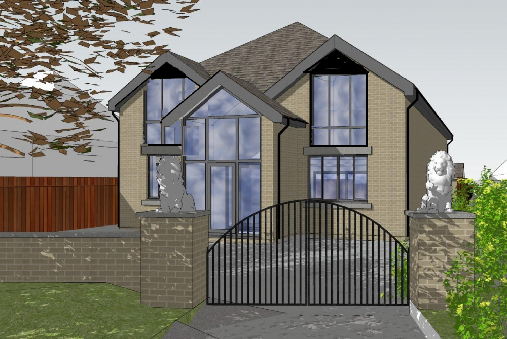
I like the layout, works really well! I’m struggling with the front elevation if I’m honest. I don’t hate it but I find the middle dormer a bit weird and the bays a bit overpowering combined with the porch, it’s just ‘a lot to deal with’. What style is this house? it seems a bit of a mishmash. I’d suggest getting rid of an element or making something lighter. When you have the walls on the side of the roof in timber frame it can also be a bit of a state when you build it. Just something to think about, what will you have on the top, GRP coping?1 point
-
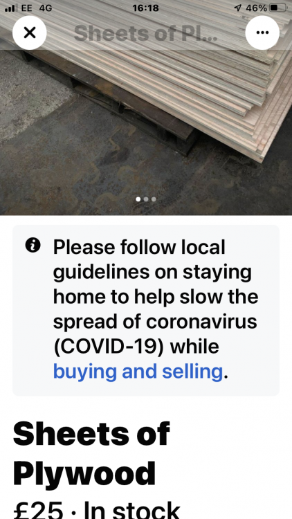
Cana deck was over £30 a sheet at one stage Even TP are down to £23 now Some of the saw mills are selling ply at £22 again some where cashing in at £35 Things are definitely better than they where1 point
-
1 point
-
One bit of good news is timber sheet material have dropped by about a third Unless you shop at Wickes ?1 point
-
If anything your pump might be slightly undersized, not over. I've double the insualtion you have and are under 300m² and we are going for a 9kW pump (double our peak head demand) Search the forum for the heatloss calculator and give it ago.1 point
-
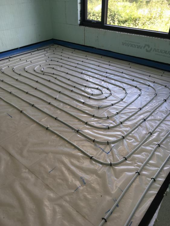
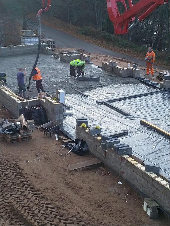
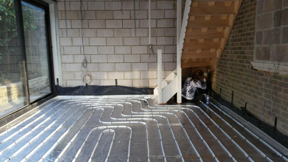
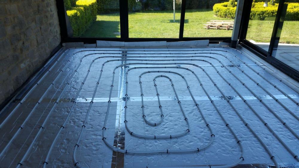
Stapling ufh pipes into PIR is easy. We laid our 100m² basement pipes in 4hours, and that was with a dodgy pipe stapler.1 point
-
All insulation has some smell when new. The volume of gas in insulation is pretty small compared to say the volume of your house and houses are typically ventilated so that the air is changed many times a day.1 point
-
1 point
-
@TerryE I have similar to yours, Node-Red, MQTT, SQL etc. I use a Radio Spares Power Bank (RS7757508) as UPS for the two Pi 3's employed in the monitoring and control of the UFH and MVHR. The RS power banks are the only ones I could find that do not interupt the output if the supply fails. They will run the Pi's for more than four hours. One of the pi's is also a wireless AP which allows connection should a long power cut be on the cards. Most of our cuts (which we have a few of) are only a few seconds. Node Red has repalced all the functions of the provided MVHR controller as it is junk, a power cut needs a clock reset.. what!! + I have added temp sensors into each of the four pipes plus a Co2 sensor in the extract pipe.1 point
-
Given that the whole heating system dies without electricity, I don't view loss of power per se as an issue. What I want to avoid is system corruption on power-fail. I have lost microSD cards in the past, so I regard these as suspect. Hence I always use SSD storage on my RPi servers and this seems to be a lot more resilient to power-fail and wear levelling failures than microSD storage. Also Linux / Ext4FS gives excellent file system resilience to power failure. All of my configuration and critical data gets backed up off server and to cloud storage -- and on a occasional basis to offline USB HDD for disaster recovery. My CH RPi3 does have a small battery backup hat which basically facilitates orderly OS shutdown on loss of power. Both my Hass.io server and my general server are configured as Docker hosts, so for example my pihole and WireGuard setups use standard containers; their build scripts are ~20 lines of bash script each and the R/W volumes are a few Mb that is backed up nightly. I don't use RPi0s at the moment, but if I did, then using OverlayFS is nicely enabled through raspi-config, and this allows you to boot and run with a read-only SD card setup. If I did need to store data locally on the SD card, then my inclination would be run OverlayFS for the root partition, but to have a separate F2FS partition for non-volatile R/W data. I generally prefer to use protocols such as MQTT on such IoT-style devices to transport updatable configuration and logged data off-board to an external MQTT server.1 point
-
If I had to tow a van again, I would make sure I find another one, and smash into it. I love seeing the A30 scattered with the remains of the Aldis or Avondale.1 point
-
i am not up to date with the regs but I think all you need to do is be able to show that theoretically it can be moved, is this not what @Crofter did, and comply to the size restrictions…..1 point
-
9-10Kw will probably be enough and I suspect the electrician will have had this sort of size in mind.1 point
-
1 point
-
Given the cumulative diagnostic effort to get @joe90sorted I wonder if there is merit in the collective brains of this forum specifying a BuildHub no-frills UFH reference design? If it was uploaded to GitHub under a creative commons licence then future self builders could ask suppliers to quote for bits to install the reference design.1 point
-
Buy the triton, get two or three tubs as you can use it anywhere you want to make the block more airtight, window reveals and other stuff, you can also paint it on to get airtight tape to stick. Very little likes to stick to the eps.1 point
-
Not essential. Depends on warranty provider, architect, design etc. Tend to stay away from to the waterbars that swell. You need a dry day to install and then want keeping dry until covered with concrete. Sika do a physical stop. More practicable. Get your outside done right and nothing else should be tested. Waterproof concrete is a waste of money. Something outside and something maintainable inside gives lowest cost option and satisfies most conditions.1 point
-
My windows were fitted, by the suppliers, with a strip of Compriband around the centre of the frame. I then fitted another strip of Compriband around the outside edge and I foamed the inside edge with Soudal Low Expansion Flexifoam. I didn't use any airtightness tapes or membranes and achieved 0.47ACH.1 point


