
Leaderboard


Popular Content
Showing content with the highest reputation on 02/19/21 in all areas
-
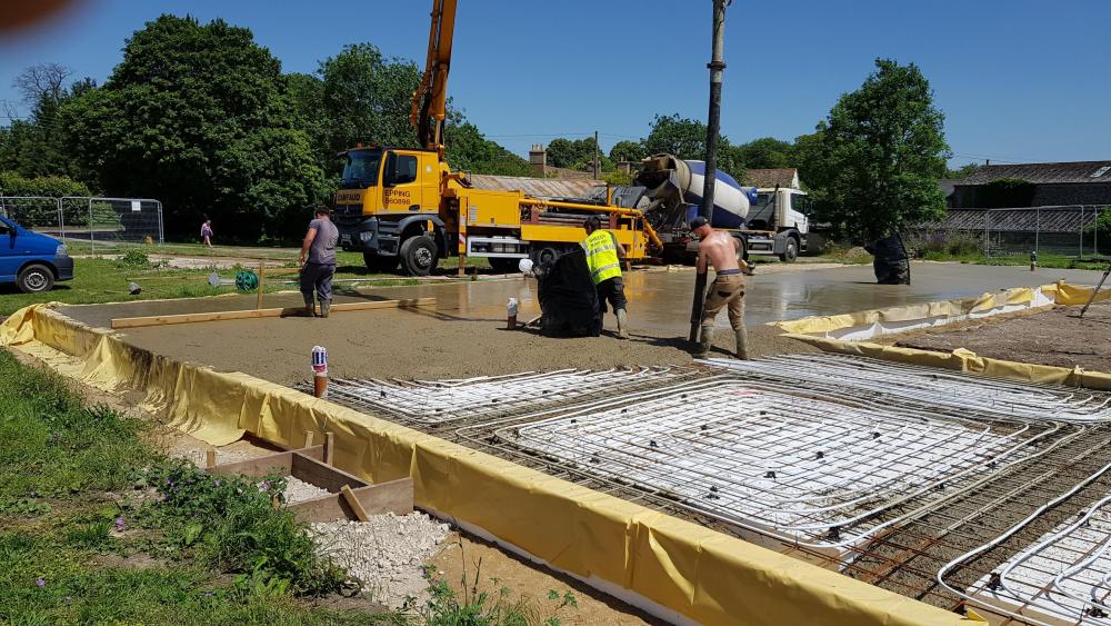
It's been a wile since the last blog entry and I didn't expect to have gone through yet another contractor by this stage but that's the way life goes! We had some good progress with the basement floor walls going up and getting poured without a hitch. We moved on to the basement roof which is a terrace for the lower ground floor so was propped with acros (decided to buy 50 as can re-sell later). That also went well - aside from some issues identified by the structural engineer. Due to a delay in the concrete pour (don't ask), managed to get a local firm in to make up the shuttering for the exterior stairway so poured them at the same time as the basement roof - not really saving money just getting it done a bit earlier. With that done we could get no with some backfilling on the sides of the building, brining up the drainage pipes from the soakaway and building some planters between the side the basement and the boundary - reusing some of the sleepers from the retaining structure we built along the boundary. Also meant we could get some blocks in to the other boundary wall and close in our neighbour - she's been great and very understanding! After applying the waterproofing and a few weeks we were able to properly backfill behind the basement. The engineer required more granular fill than the beautiful sand we had removed so that hurt a bit but never mind we cracked on with that and backfilled against the eps sheets we laid against the double drain which was against the waterproof membrane. This took a lot of time compacting in 150mm layers but we had a big excavator on site to help and a few bodies. With the backfill done we could start on the ground works for the lower ground floor. Unfortunately a ground worker though a boundary wall should come down (I wasn't on site) so that made a lot more work - was the remaining part (about 8m) of a 20m long wall so more to get rid of and more to rebuild (he didn't last a lot longer). As this floor is below street sewer level we installed a1.5m x1m pump station for foul water/sewage - the upper floors go direct to the sewer so we can last a while if this get blocked up - though it does have 2 pumps, an alarm etc. Issue really was that it had to be pretty deep due to the distance from the furthest bathroom - though the groundworks guys did a great job with that. We found that a large tree we had felled (with permission) had it's stump in the way so a day was spent getting rid of that -managed to find a neighbour to take it + some off-cuts of timber! You can see in the pics some decent size I beams we installed to make a king post wall retaining our neighbour's new fancy house - the beams were 9m long so 6m in the ground and 3 out to retain the excavations. Luckily I could call upon the firm I used for the earlier retaining king post wall who happened to have hired in a great new machine which they used for 2 days to make the holes and we then used the 13T excavator to drop the steels in place - this was completely heart in your mouth stuff. The steels were too long to be lifted so the guys cut a wedge in them 1m down from the top to wrap the lifting chain around to get more height - worked great. A bit of concrete later and we had 4 solid steels which we could install the sleepers in to. Rest of the ground works just took its time, we're 3.5m below ground level so all materials had to be sent down a home made chute but more problematic was the removal of 160T of additional excavations from the trenches and final levelling. how do you get that up 3.5m? We hired a long reach HiAb with a clam shell bucket and paid extra for a tipper to be loaded at the rate of 1 per hour. Took it's time but we got there eventually. We still had some final trenches and drainage right at the front of the site which of course resulted in 30T more excavations which we put in dumpy bags and got the HiAb back to lift out and put in a tipper - though kept 10 on site as a safety barrier and to reuse for backfill later. And the long boundary wall - well we re-built that much stronger than it was and also a little higher to fit with a future stairway - not looking forward to the rendering cost for that ! So we're now ready for the concrete blinding layer and then we get the steel fixers in for 10T of rebar for the next slab. I hope it gets easier after that! and hope we keep the current team for the duration....5 points
-
Thats all that needs to be said really. The consequences of the error are clear. No 32mm, no sign off. Unless there's reason to suspect mis-communication rather than addle-headedness, then don't pay ( or pay an appropriate amount) until it's put right.2 points
-
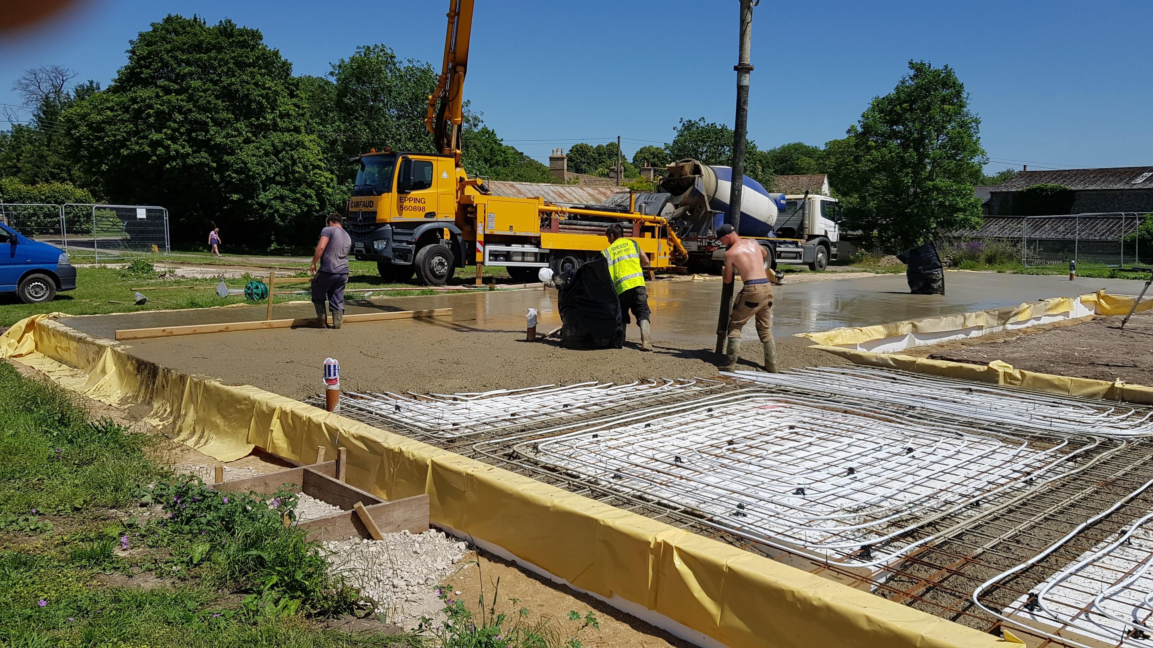
Well, a few weeks have passed since my last past. We finished up the road and last post we had scrapped back the house footprint. I feel like we haven't come that far since then, but in reality we probably have actually now that I look at the pictures. Once we had scrapped back the top and subsoil we got the levels down to where I thought we should be. The house was meant to have FFL of 138.5m (referenced to sea level of course!) but I increased the height by 0.75m. It was just too low in the ground for the plot and the driveway would have ended up higher and now seems to be in the right place. So first full week at it, I was basically running around organising things as you do. I gave Jewson about zero notice of all the stuff I wanted. They gave me good list prices, 90% off with my self build credit account. I tested these on the internet and a few others merchants and they were decent. They delivered the mesh and underground drainage pipes, mesh castles, visqueen etc all in quick time which was good. I also took delivery of my container - which was much required and has been a god send to store everything. On the first day when I was out, the groundworkers were scrapping back to ground bearing soil, but found a soft patch at one end - instinctively they dug another 500mm deeper to get hard ground. Then called me to say we had an issue. They felt it was quite soft, I turned up - had a look it seemed softish but not overly. However I have no experience - fortunately I called the SE and he came straught by to have a look ...wasn't an issue and he told us to continue. Phew. I'd ordered type 1 for the sub base. I did price both type 1 and type 3, but there was quite a difference of 3-4 per tonne. I needed 120 Tonne (turns out actually 250 in the end). I checked with Tanners who had stated Type 3, but they said if it was a struggle type 1 would be fine. Plus I checked with a local guy who does passive foundations and he said they just use that so all ok. We continued the scrape down, then we laid a geotextile and covered with the type 1. What was immediately apparent was how wet it was, that extra dug down section filled with water quickly to form a lovely swimming pool. From here we tried to stone up a little more, but stopped due to rain. Then the guys decided we needed to get that land drain in to dry it up. I have used twinwall perforated pipe to do the land drain (under the guidance of my groundworkers) then added Tees wherever downpipes are going to be. This saves costs as then you're not digging another pipe above it later on. You can just roll the tees up and drop the downpipes into it. I discharge directly into a burn too so makes sense. I helped with the drains and we used the laser the set the fall ( @LA3222 ) I know why you like it so much, great tool and makes it dead easy. I did nearly make a schoolboy error and lift the full pipe up in the pea gravel...before the groundworker stopped me Once we had the drains in this has helped no end with getting the water out, and allowed us to continue a little more. In between this the power connection was brought on site, I had 6 poles put in from 3 fields away. I managed to also get them to hide the transformer pole in my woods which was ideal as I had planned it in the corner if the plotand that would have been visible always so a good win. The trench was also repositioned around the outskirts of the plot so that if I ever build another house ( my retirement bungalow) in the front garden I don't need to move it again. 6 poles put up in a day, then a week later cable pulled and terminated. The connection currently resides under the ground about 15m from the plant room, once I'm ready. I'll dig the duct to there and then I can call them back and pull it into the house at my leisure. We got a little bit of rolling done on the first layer of Type 1, but it's been mega cold and snowy for a few weeks which has stopped us. One thing that has been a pain was the test holes left big soft spots. We had to dig these out completely and fill with stone. The groundworks boys said he always have this issue and would be better if the SE put them off to the side. A good bit of info for others. So since that point it got basically rock solid cold. little happened for about 10 days just due to weather. Then last Thursday after postponing him 5 times, got the surveyor on site. I had marked up various times using the TOPO stations and tapes, but wanted very accurate positions on site for the walls and so I can get the ducts and drainage bang on. I spent days on the plant room design and layout which is now hopefully pretty good. The surveyor and I put all the profile boards up outside the footprint which went well, I was 400mm off the actual CAD position I had given for the house. Which considering I was using tapes from topo points which were 80m away wasn't bad. I had already cut drains in so we just moved house position quickly by offsetting using total station. The profiles are in and all good. So this week we managed to stone up more, the boys done a bit of rolling on Tuesday - in fact I even did the rolling while they moved stone around. The stone is compacting but not as hard as I would and as quickly. They had to put a thicker layer on that the 150mm due it being so wet it would just bubble up. But the stone is soaked, and taking a while to drain off through the type 1 as my stone seemed to have loads and loads of fines. Now If i go back to the start of this post....maybe I should have bought that Type 3, but we are where we are! We rolled it down, then got another layer on and continued to roll it. It was still quite spongy at the end of the other day in a few places but we haven't finished rolling this layer just due to it being wet. The boys definitely put on thicker layers than stated and we rolled the lower layer less than the required 16 passes. I was having a bit of a hairy canary when I cam home and started to doubt what had been done, I was checking the roller weight and spec religiously against the KORE manual, and then getting worried that it would leave the lower layers too soft. It's hard here as, how hard is hard enough as I don't have any experience of laying a sub base and reading on here it should be rock solid. So I was back and forth the next day to site, jumping up and down, seeing how hard it was. I made a plan the night before as it was concerning me, that if needed I would just strip it back down a layer and re roll that bit and not to worry myself too much (the boys keep telling me to put my worry beads away) that we can fix it. Now that we have had two sunny dry days with no ice, it has drained off well and feels better actually and I talked it through with the groundworker that i was worried and didn;t think we had enough passes, and he help reassure me somewhat (and I trust him) that albeit the textbook says 16 passes and 100mm layer that, it simply isn't possible here to do it in the 100mm layer as the roller would bring the water through at that point and we need a thicker lower layer. Now that we are up a but and it's drying it should compact better. It's now pissing it down for the rest of the week and we can't do anything. However he has left me the roller over the weekend, so I can roll it to my hearts content which will make me very happy. Hopefully we get a couple of days dry at weekend and I can et that done, then they will be back Tuesday to hopefully get the last layer or two on and bring it all up to the correct level and then we can mark the ducts and drains and get them dug in to the stone. I was quite surprised at how not flat my flat looking plot was. Standing looking at it is quite deceiving, at one end of my 20m length footprint, I needed around 150mm stone, at the other end I will end up with 4-500mm stone which is quite remarkable. To the eye it's very deceiving. Having the laser there is great and helps make it all very easy. Lots of challenges, on site with weather and generally getting organised. Also the stone compaction and not having done it before definitely caused worry which unsettled me, simply I think because there's nobody else really to take the responsibility as ultimately it's for me to say what's ok and what's not. Having a major responsibility is not a daunting thing for me, I work at a high level in a business and directly responsible for managing and being the technical expert for very large value and complex equipment. However there's something about being in unfamiliar territory here and doing it for the first time with nobody to else to take the responsibility which is both exhilirating but also slighlty terrifying. It's like when you take your first foreign trip without your folks, or when your new born baby won't stop crying. It's a challenge and when you get through it, it's good. You just need to feel your way through and make as best decisions you can and rely on the people around you. I can say I am absolutely thoroughly enjoying myself. I have loved being out my home office (daughters nursery!) and being out and about on site. I cannot wait till get further ahead, the kit comes, which is planned for April now, and I can work up there every night in the spring and summer. The kit has been delayed somewhat due to messing around with L shaped combination skylight windows for a week, I can firmly say trying to get them figured out has been a PITA. Also, I had added the angled reveals at the top and bottom (which I may scrap tonight!) but that's another post for another day.... Lots of pictures as that's what blogs are about. Test holes sense having them dug below.2 points
-
I think it’s as good excuse to make a bit more profit We have a large independent BM near us About 100 staff They have mountains of timber stocked up over the lockdown I can bet my bottom Dollar that they sell it at the new price2 points
-
Why should they when gas is <3p/kWh1 point
-
but if loop 1 gets hot quicker (smaller run) the valve would then close or reduce right? if it does then more flow (i.e quicker hot water) will be pumped to the colder circuits fixing my issue i'll install soon - only one way to find out1 point
-
Yarp, got sick of looking. There does not seem to be many retailers selling them, most are your RHI companies and they can poke that where the sun don't shine! I could only really find Wolesley, SWAT and some eco store. Midsummer have started selling them now - I say 'selling', I mean ripping people off? Went with Wolesely, I'm just waiting for the obligatory 'we are out of stock' email on Monday morning. If they are, it's no drama as I won't be fitting it for a couple of months. But yeah, the market isn't very competitive for these?♂️1 point
-
Hi Sean, looks nice. What type of cladding is on the outside ? My only comment and it's purely from a constructability end is maybe look at the bathroom locations with regards what you plan to do with the soil stacks. Best of luck with your build ?1 point
-
What does passive actually mean? There's a technical standard defined by the Passive haus institute detailed above which you can go for but that's just a vanity £5k spend on a certificate. It basically entails the level of insulation/heat loss and airtightness of the structure. In mine, its 300mm insulation in the walls plus 35mm dead air gap, 400mm in the attic, 300mm XPS under the floor tapered to a minimum 100mm at the dpc edge (so totally enclosed foundations) and triple glazing. All airtight to a measured 0.17ach @50pa. In heat loss terms of U values, walls are 0.1u, roof 0.1u and floor 0.12u. All windows/frames better than 0.8u. A 1930s cavity wall? Well the cavity is likely to be small, so I'd guess the u value would be around 0.5u. My running costs in the past freeze, 15th of Jan to 15th of Feb for heating and hot water around £65. £2 a day. Whole house at 22 to 23 deg plus warm attic circa 85m2 too. 14 zone UFH cast directly into the slab, 155ton heat store. Around 1.5km of pipes! 400l hwt
 1 point
 -
Thanks, I had not seen that documented so succinctly before. My house meets those energy requirements and I hope it will meet that air tightness level (will be getting it tested later this year) Like many I strived to get somewhere close to passive house levels but without paying to have it certified s such. You know when you have got it right, that your heating bills are a minor part of your total energy bills. In my case about 1/3 of total energy used.1 point
-
In short, no1 point
-
I quite like the single storey bit giving a good balance between living and bedroom space. I don't quite get the elevations but maybe it will be fine when completed. I think I would want to see a 3d render before I committed to this.1 point
-
Planning usually prefer a traditional or modern approach, smashing the two together doesn't always go down that well! What way is the building orientated, do you have a site plan?1 point
-
If you have Heatmiser Neostats, simply set the overnight to 5 deg lower than daytime. Even in a poorly insulated place you'd be unlikely to drop this much. I'm guessing that as you have ASHP then you are decently insulated and draught proof. Not heating some of the house as high as the rest will save some pennies but if your internal walls are not insulated, a cold one could attract moisture if the temperature in these is too low. The cost difference between 10 and 15 deg is not huge and bear in mind that insurance policies usually have a minimum temperature required around the 13 to 15 mark if you're claiming for frozen pipes.1 point
-
I have written up design and specification briefs. Attached drawings which while are not fully spec but are scaled. I send an email or call and follow up with the attached drawings. Seem to have a positive chat, then nothing or offers of yeah course we can do that give us a week....best so far a quote from mid January which only has half the detail. Most are referencing COVID and working from home , as I am but I don't take three weeks to reply to an email.1 point
-
Yeah we will probably go with NW water as they where the cheapest last time But these utility middle men are handy for getting an idea Plus they will plot out everything on a drawing1 point
-
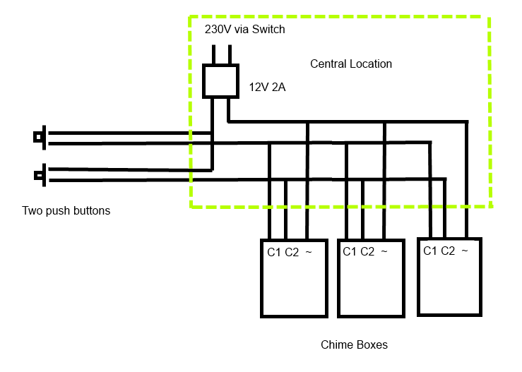
Presumably you want each button to sound a different chime so you know which door to go to, and the three chime boxes are for coverage in different parts of the house? Quick google found this range can do that.. https://doorchimesuk.co.uk/catalog/product_info.php?products_id=629 That model supports lots of different wiring options including mains and built in transformers. The circuit below is just one possibility based on their option B using an external transformer and chimes in parallel. You would run two core cables for the push buttons and three core to the chimes all to a central location like the CU where the transformer and a junction box is located. You might consider running extra cores to the pushbuttons as spares or future use. https://doorchimesuk.co.uk/pdf/CROMA_230.pdf It says each chime box needs 12V at 0.5A so I'd use something like a 12V AC 2A transformer. With more time it might be possible to eliminate the external transformer using one of the other wiring options.
 1 point
 -
How long is the run, is it in duct? Are we talking 25m here or 250m? Is the ground above the trench still just rough made up ground - i.e. no reason why you cannot re-dig it easily enough? Personally I'd probably just dig it up, lay in a 32mm and leave the 25mm next to it just in case there is a future benefit to it being there - you never know - could even be repurposed for something else.1 point
-
The plumber will no doubt say it’s fine, as he is being paid by the builder so will be on his next job too. You will be stitched up. the plumber won’t have showers going, washing machine running garden taps etc he will say it’s fine, or as others have said allow for future proofing for anything such as sprinklers. The reason the designers in the utility company specify things is so builders don’t just buy the cheapest product at the merchants1 point
-
Does it need to be a sun pipe? There are quite a lot of regular roof lights around. The key is to find a good installer as its important to get the upstand built correctly to the manufacturers spec so it doesn't leak. They can be made less than 150mm high which is the normal allowance before Planning Permission is needed. See page 38.. https://assets.publishing.service.gov.uk/government/uploads/system/uploads/attachment_data/file/830643/190910_Tech_Guide_for_publishing.pdf Source: https://toughenedglasssystems.co.uk/product/skylights-rooflights-1000-1000/?gclid=Cj0KCQiA4L2BBhCvARIsAO0SBdYDHw4pi1LTL9uE49WF2s7X-UEy1KGVPUxOO5Y4Yf-2WbykSDWT_r8aAtZUEALw_wcB1 point
-
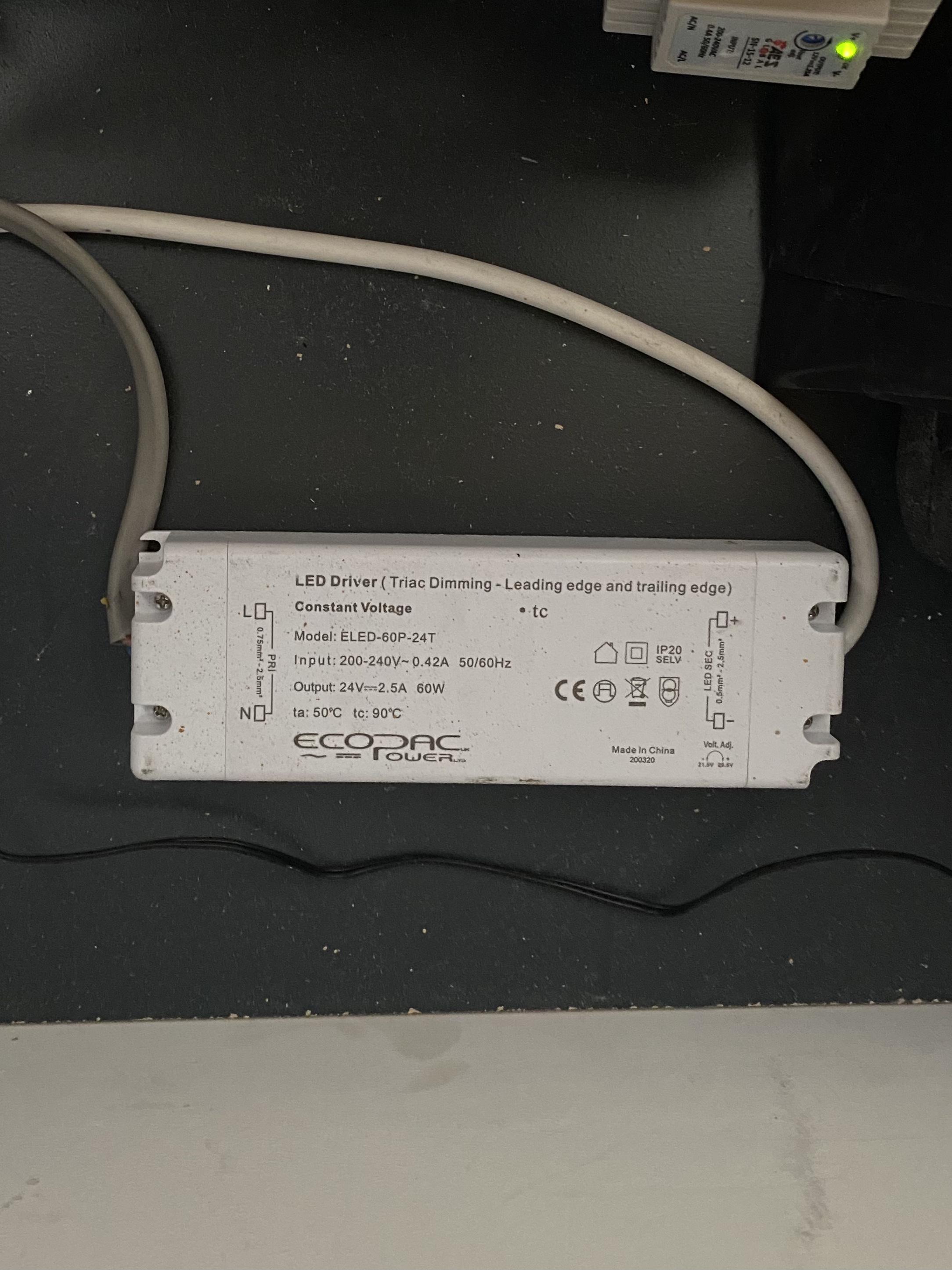
You just clip the connector shown to the end of the strip and then the two wires connect to the power supply. It seems to have a plug on the other end that would fit a specific (syndeo) power supply, but you can cut that off and connect to any power supply with the right specs.1 point
-
Mass loaded vinyl seems like a cheap option at adding density. the independent wall not touching the original would be good, fit18mm plywood where the tv will go and then plasterboard over that will support tv no probs good luck1 point
-
This is how mine has been set up and these guys https://www.led-lighthouse.co.uk advised on what was needed and is all working well. 1st pic dimmable driver connected to circuit 2nd pic plaster in profile with 4 meter led strip dimmer switch controls it with varilight vpro modules

 1 point
 -
Yes he will tape and plaster over.1 point
-
Using the metal stud is fine But you will have to Vlad it with cement board prior to plaster-boarding As PB is considered combustible1 point
-
I posted regarding this after the origenal . Brexit vote I asked the timber merchant How can Brexit effect English oak when it grows here ?1 point
-
I’m also hoping the Mars probe landing today can bring some timber back . Probably requires less paperwork than the ‘frictionless’ boarder we have . Might be quicker also !1 point
-
I think to cover the rear wall with tarp when it was being plastered.... they kinda got left up there for a while1 point
-
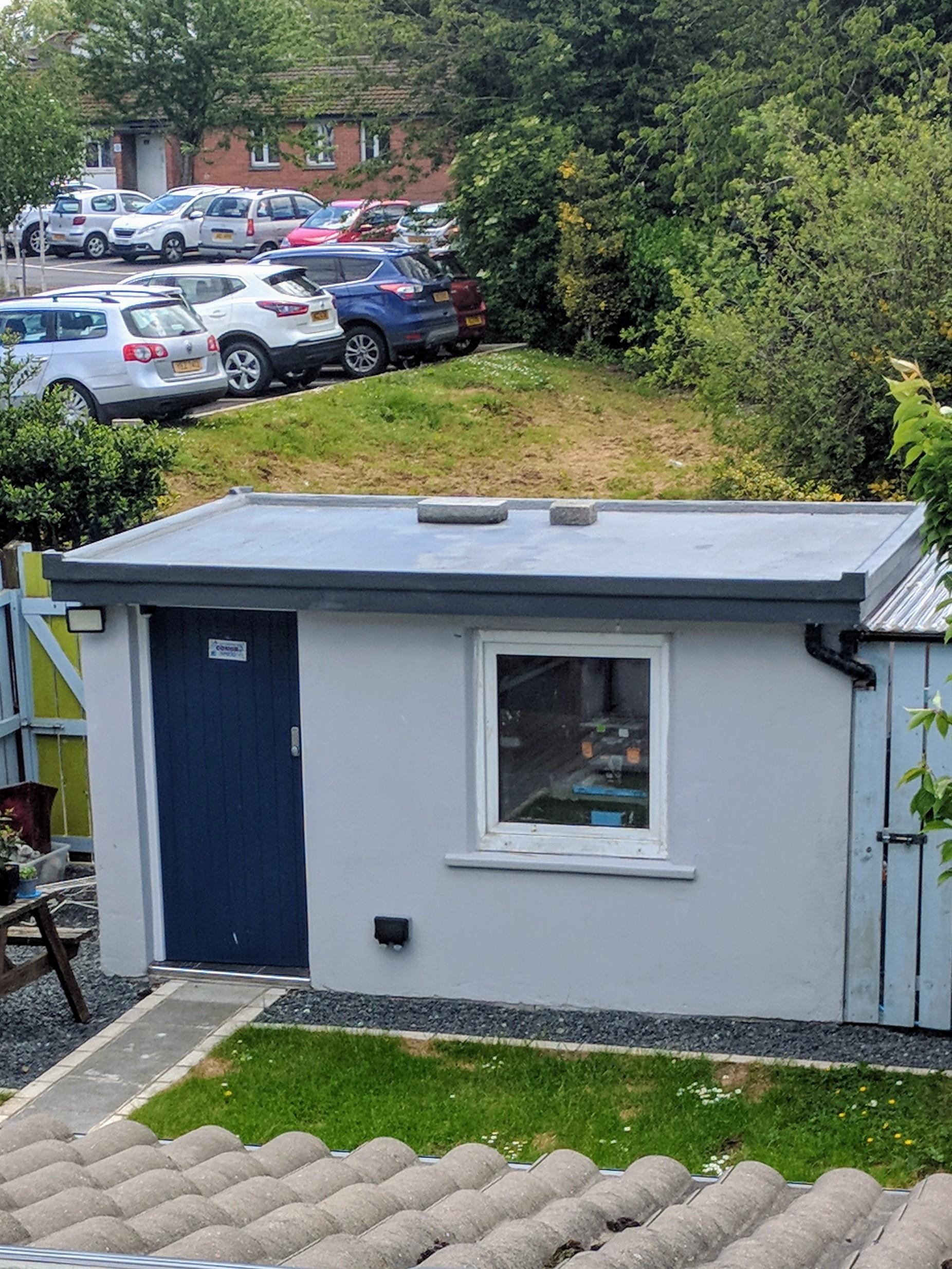
The height thing. That is measured from the ground adjacent to the building. I would say it is measured from the path / gravel along the front. It is only just higher than a standard door, so what is that measurement? If it scrapes in under 2.5M you are home and dry. It does not matter if the ground is sloping and at some other point the height might be more. And it's built of block, so the non flamable if <2M from boundary is taken care of.1 point
-
Very sharp! ? (What are the blocks on the roof for?)1 point
-
You could take the top course of block off and put on a flat roof so the building is under 2.5m high? That's how I did my brewshed.
 1 point
 -
Is anyone likely to complain? If not you could just build it and see what happens. If someone complains the planners will send you a letter saying you need planning permission and you can make a retrospective application. If its refused you can appeal. If that fails you would have to reduce the height or knock it down. If the planners take no action for 4 years then you can apply for a certificate of lawfulness on the grounds they can no longer take enforcement action.1 point
-
Welcome! (I used to love Sue's Cafe in Norwich market before it all burnt down. "One belly buster moi luv!" ?) Why an elevated pad that high? Any form of insulation in the floor?1 point
-
https://www.planningportal.co.uk/info/200130/common_projects/43/outbuildings Outbuildings are considered to be permitted development, not needing planning permission, subject to the following limits and conditions: Maximum height of 2.5 metres in the case of a building, enclosure or container within two metres of a boundary of the curtilage of the dwellinghouse This is UK wide law, you are at breach of it I'm afraid. Check if you can apply for a retrospective planning permission - even if positive, due to proximity to the boundary (< 1 m) you'll be limited as to what roof materials can be used to comply with ' constructed substantially of non-combustible materials ' rule.1 point
-
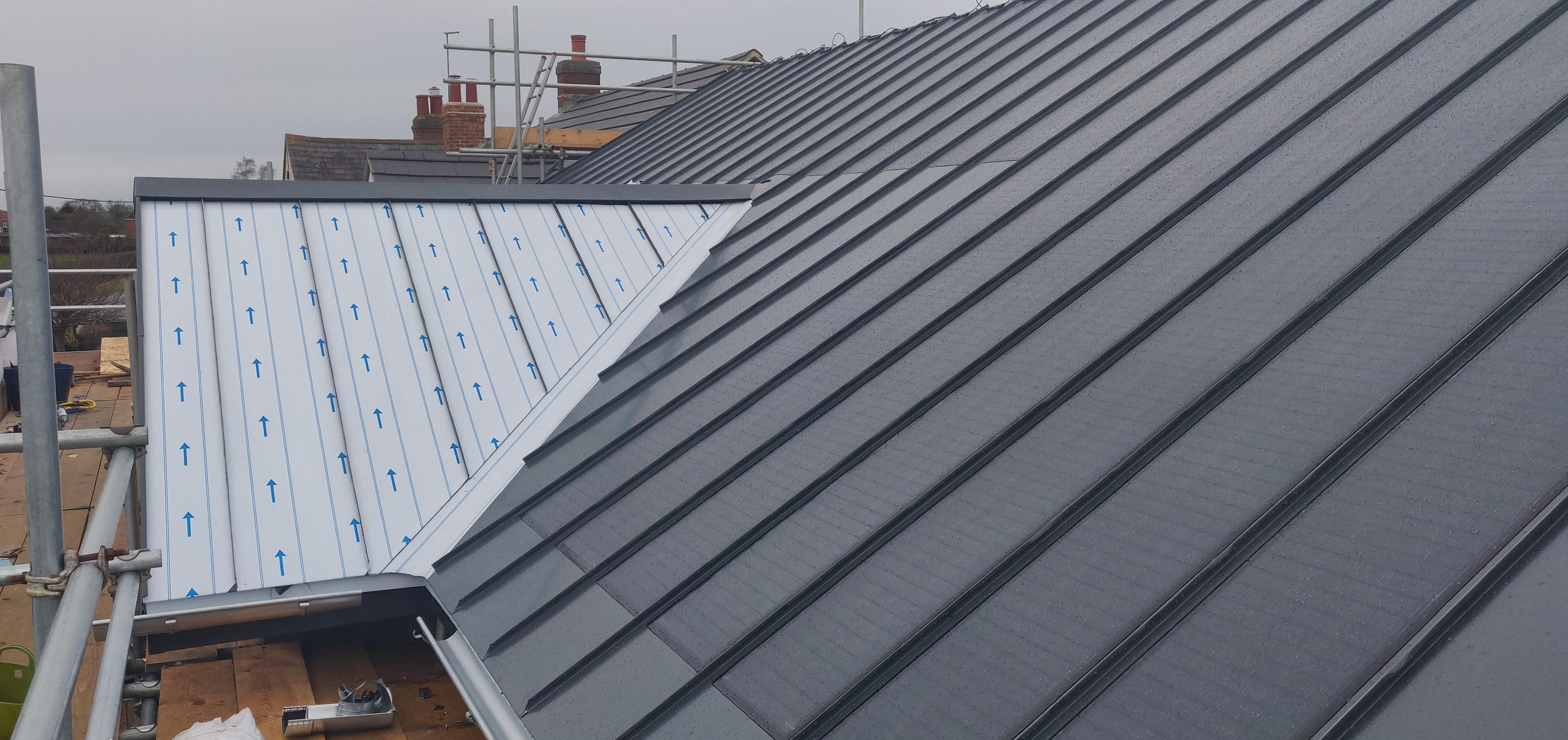
I'm really pleased with the way the solar panels and roof is looking
 1 point
 -
£50 a week to heat what? floor area? heating only? Hot water too? internal temp set point? location in the uk? house construction? UFH/Rads? air tightness? insulation levels? large family/working from home?1 point
-
Welcome. I am new here also but have planning consent for our new build. When we started out the first thing we did was arrange a quick free of charge meeting with the local planning department to discuss the location and basic ideas for our build. Whilst clearly they could not give a decision at that time they did say that they saw no reason why we should not pursue it further. They provided some pointers as to how it should comply with the neighbours etc. Whilst this might be currently difficult during Covid times for a face to face you may be able to get an online meeting arranged.1 point
-
We had one years ago at a previous house and I think it was made by a company called Balmoral. It gave perfect service and very rarely needed to be emptied compared to a normal tank which we had at the house we moved to. The Balmoral one we had was silent and we only had it serviced once in 6 years which I think cost £70 but that was about 15 years ago. Our self-build is on mains but it wouldn't bother me at all if I was looking at a treatment plant instead, and it would probably be cheaper on an annual basis than mains (though would obviously take years to recoup the install costs before someone says). Well, that was my experience for what it's worth and I dare say they're even better these days. The only irritation ours gave was it was difficult to hide the hatch and the electrical box for it but it had been fitted by the previous owners and could have been done much better with some thought. That would be my advice, carefully consider where you position the tank and the control box if it has one. Good luck.1 point
-
We’re getting there! flooring, kitchen and stairs, just bathrooms to go. It’s great to see it all taking shape as the finishing jobs get done. Not that it’s all gone to plan. The first job we tackled was to get the floor down. We wanted to get it done before installing the kitchen rather than having to work around the units. As the kitchen is part of the open plan living area on the first floor it meant doing the whole area some 70m2. It’s a lot of flooring and we needed something that was easy care and tough. After a fair bit of looking at the options, we opted for lose lay vinyl. There seem to be three vinyl options, adhesive plank, click and loose lay. I didn’t fancy sticking down such a large area and we have a couple of floor access panels that I wanted to keep access to. The click version is not dimensionally stable and requires an expansion gap and it’s not designed to have heavy objects such a kitchen units on it. Loose lay ticked the boxes, dimensionally stable, OK with heavy objects and as it turns out the simplest to lay. Karndean and Amtico both have loose lay options but they come in at £30-£40 per square metre. By lucky chance we found a commercial flooring supplier Quadrant who have a loose lay flooring system Salto with a spec pretty much identical to Amtico Access but at £22 per square meter. The planks get laid onto a three metre grid of tackifier, a non setting glue that just stops the tiles from sliding rather than actually gluing them down. If a plank gets damaged you can simply lift it out and replace it. Laying the floor could not have been simpler. In a couple of places we found that the tackifier was just not enough and we ended up fixing one or two end of row planks with a patch contact adhesive. With the floor down we could then start on the kitchen. With no stairs in place we used our electric winch to get the cabinets and appliances to the first floor. We bought the winch to get the 80kg MVHR unit onto the second floor and it has been invaluable in getting flooring, doors and many other heavy bits safely upstairs. With the units all upstairs we made a start putting the kitchen together. We had gone through a couple of design iterations and of course the one we settled on meant that the electrical sockets we put in when plaster boarding required moving to meet the 300mm minimum distance requirement. It’s easily fixed with a splash back so not a real problem. Our appliances are built in, a first for us. So we started out by getting the fridge freezer into its tall unit. There certainly is not much clearance, having carefully got the fridge correctly located I discovered I could not fit the hinges with the fridge in situ, so had to drag it out of the unit. Unit doors fitted and fridge shoe horned back into the unit. You then have to connect the fridge doors to the unit door, a bit fiddly but it all working nicely. Pushed the unit into place only to find the lead was a couple of centre metres short of the spur socket installed for it. Dragged the fridge out, made another hole in the carcase and re-routed the cabling, put fridge back in unit, push unit back into place only to remember the unit had not been secured to the wall after the second cable hole had been made…needless to say there was a bit of cursing as the fridge was dragged out again! A least if we ever have to fit another we’ll know how to set about it. The kitchen has a long set of linear units, which should have been a doddle to install against a nice straight wall. Unfortunately the wall they were getting installed against was the one that didn’t get braced properly on the final pour. Needless to say the units all required spacing out from the wall to form a line. A task not made simpler by the design which has two rows of bridging units over the hob. These are mounted on a wood frame constructed to fill the gap, which of course I cut before remembering the wall was not true. It didn’t take much work to re-jig it thank goodness. We also had to construct the shelving unit as this was a bespoke piece, to make the position of the boiler housing correct. With the linear section of the kitchen built, it was time to build the island. As it turned out this was a much more straight forward proposition as it didn’t involve and dodgy walls. It did involve cutting down a unit by half and cutting the composite worktop. We discounted doing an under-mount sink as we were cutting the worktop and any router chatter would ruin the worktop look. In any event the island went together nicely and the kitchen looks the part. One by-product of having the kitchen done was the completion of the electrical circuits. We duly called back in our electrician to do the final checks. With a couple of minor changes it was all passed. A significant mile stone to pass regarding building controls. Our electrician has been brilliant and supported our work through the build. Not something that all electricians are prepared to do and we were fortunate to find such a good one. It’s been cold and despite the high level of insulation in the house we were getting uncomfortably cool and decided it was time to get the gas boiler connected. We calculated our structure requires about 68w/degree input so very minimal heating should be required, making heat pumps not cost or energy efficient, hence the gas boiler. The boiler feeds two towel rails, no radiators. All the pipes had been put in place long ago before plastering and painting. A bit of a risk but we pressure tested everything before we put the plaster board up. When we finally got round to filling the system and pressurising it we found we had a leak and water was running down behind a radiator. Careful removal of plaster board revealed the cause, I had put a plaster board screw straight through the pipe! With the damaged pipe cut out and fixed, plasterboard and plaster re-done. I put the radiator back up and pressurised the system again only to find another leak. This one took a little longer to find. Again it turned out to be pipe damage, this time on the other radiator, and was one of the radiator mounting screws. Not impressive and something we’ll conveniently forget. At this point the system was holding pressure and all looked good, time to call in a gas safe man to commission the boiler. Called a couple of local gas fitters only to discover they were not prepared to commission a boiler they had not installed. Tried “check a trade” and one of the gas fitters replied saying he wanted to see the installation before taking the job on which is fair enough. Well, he turned up looked at the installation and said he was prepared to do the commissioning, he also pointed out that pipes within 1M of the boiler should be copper and not push fit fittings. We’ve been reciting building regs in our sleep since starting this project and had completely missed this requirement. We had done the gas pipe in copper of course, but why the water pipes? Still no point in arguing….so out comes the carefully installed kitchen cupboard and pipes replaced. Pressurised the system and guess what a leak, this time in a push fit with the new copper pipe. The pipe had caught the o-ring and cut it in two. Easily fixed but none the less annoying when you can’t see any benefit from changing the last meter of pipe to copper. All fixed time to call the gas man in, only to discover his colleague had a covid contact and they were all waiting on test results. Two weeks elapsed before he could come back and the boiler was commissioned at last. Bliss watching the room thermometer slowly creep from 9C to 18C. It certainly makes turning up on site a lot more welcoming. Last but not least we got our stairs in. We had bought the stairs from Fontanot last year and had agreed that the manufacturer would store them until we could take delivery. So they had been sitting in packing crates in Italy since last June and we didn’t get them delivered until October. They were well packed and all we did at the time was a superficial check of the contents, no damage, all present and correct. The stairs are modular and very minimalist, they give the impression of floating in air. Each stair tread support is connected to the next with an M20 bolt through the steel tread supports and spacing shims. It gets built from the top, so you start by installing the head bracket, then each tread until you get to the bottom step where another bracket secures the foot. On the ground floor this is fine, on the first to second floor it isn’t as the stairs don’t terminate on a horizontal floor. The manufactures representative had been on site so was well aware of this, the drawings also showed this but the stair kit shipped was identical to the lower stair. We contacted the supplier who was very responsive and would get back to me with a solution. Time ticked by with no word, so we contacted them again. They rather sheepishly admitted they had no “stock” solution and would have to make up a special bracket. Time ticked by again and we contacted them for progress. What they came back with was not elegant to say the least and would have spoilt the line of the stairs which are a feature of the build. We took a look at alternatives and realised that modifying one of the standard head brackets and mounting it inverted would provide a much better looking solution. New head bracket ordered from Italy along with a tread support. The tread support was modified to bolt directly to the head bracket. Progress at last. Modified bits arrived and unpacked, modifications just perfect, but they were the wrong colour...doh! So we are not out of the woods yet. It will get resolved just it is proving a rather painful process. Back to installing the ground floor stair. Working from the top, the steps adding one at a time using hand rails rods to maintain positioning. The bolts get torqued to 140nm, even so the stairs moved around rather worryingly. Every third step we put a wooden prop to support the construction. By the time you get the bottom step there is a LOT of weight in the structure and it did not feel at all firm. The bottom tread support bolts in to the floor. In our case this is an insulated concrete raft, which is fine as it is strong and plenty deep enough. However it does have a lot of re-enforcing rod, needless to say we found it on two of the four holes. Drilling through with a masonry drill should be possible, but we didn’t manage it and ended up ruining two good quality 12mm HSS bits to get through it. I’m sure there are better ways to do it, over an hour per hole. At last we could bolt down the bottom step. With all the steps secured we left the props in and installed the had rails and four stabiliser brackets. With some trepidation the supports were removed and a tentative test at climbing them was made. They were solid as a rock! Result.1 point
-
The only reason you have to upgrade a septic tank is if it discharges to a watercourse. If the ST is working and drains to a land drain then there is no present reason why you have to replace it.1 point
-
What was the total depth of the hole you dug? The 300mm cube you fill and test should be below the bottom of the proposed outlet pipe depth. So if the drainage pipe itself will be 300mm deep, you fist dig a 300mm deep hole (width is irrelevant), and then AT THAT LEVEL you dig the 300mx300mx300mm test hole. Fill that hole and allow it to drain overnight. Then refill to 300mm the next day and time how long it takes to drop from 225mm to 75mm, which it sounds like you did. You should refill a further two times and time these in the same way. Then calculate an average. Hope that all makes sense! You then put the figures through an equation, which I can find for you if you are interested? Let me know. I would personally try another hole in another area. If there's any chance the area you tried the test hole in has previously been compacted, this may have an impact. I say all of this because it is exactly what happened to me recently. The first hole chronically failed. I ruled out a drainage field based on that, but then decided to try an other hole in another part of the land, and that had great results. If you went for a Sewage Treatment Plant, where would you be discharging to? A stream?1 point
-
Get a big roll of plastic. Double sided tape it to cover the whole walls with as few joints and penetrations as possible. Anywhere it has to join, overlap by 15cm and use wide foil tape (also screwfix/Toolstation) along the joints. Overlap it with a horizontal plastic sheet covering the bottom of the ceiling joists. Take it into the window bays etc as well and seal it up to the frame with tape/silicon. Ideally join it to the VCL/DPM at the floor, or seal it round the bottom edges. You're aiming essentially to make a complete plastic bag inside the room. The double sided tape can be a generic one from Screwfix etc, just needs to hold the plastic in place while you put the plasterboard up: ultimately the plasterboard will hold it in position and clamp it onto the tape/silicon round the edges to keep the seal tight over time. You can also use some staples to hold it initially in places it wants to pull off the tape, then just put a square of foil tape over the staple. The cold side is the side nearest the outside. Water vapour will travel there from the room (e.g. through little gaps between cut bits of timber, through gaps that form as the timber shrinks, through tiny natural cracks that will open up in the grain of the timber itself, etc). Then it could condense into liquid water and start to cause problems. Same basic thing as when you wake up in a tent on a cold day and the inside surfaces are soaked with the water you breathed out in the night. The "thick shiny vcl outside of the timber frame" should be (and likely is) a breather membrane rather than a VCL. In theory that will allow vapour out of the wall and into the cavity before it condenses. In practice there can be a mismatch between the rate vapour gets in from the room and the rate it gets out through the breather/cavity : the more you can keep the moisture out on the room side the better. The external breather and internal VCL work as a "belt and braces" pair to make sure the wall stays dry.1 point
-
Having done a large renovation project and turned an old 1770s vintage wreek into a fantastic Home we decided that living in Cheshire was no longer for us, so we sold up and moved, to be closer to family in the Southern Lake District. However the journey was far far from straightforward, we really had no idea what we were looking for, was it to be another renovation project or a self Build? Having viewed around fifty ‘oportunities’ ranging from dilapidated houses, to an old pub, to a closed garden centre, we gave up!! Then about six weeks after ‘giving up’ Debbie had to come clean, she’d not actually given up, but had been searching online and she thought she’d found what we were looking for. So we arranged to view a rather sad looking dormer bungalow on a very wet, cold and overcast March day. Once into the property we both realised this was the one! So we bought it and moved in. Having lived in the property for a year it was clear that this wasn’t a renovation job, so the bungalow had to go. The next step was to decide what to replace it with. Although we had it in mind to downsize we missed the larger rooms of our previous home and. According to my interior designer (Debbie) we needed larger rooms so our furniture would fit.... Living in the old bungalow made it obvious it was the wrong way round, the two bathrooms and the bedrooms had the best views. Also because of the shape of the plot, an L shaped house would make the best of the space and the views. Once we had our requirements clear, a design brief was produced and a local Architect appointed. A series of design options were produced and after some tweaking, final plans drawn and planning permission sought. Prior to the submission of the planning application we walked round our neighbours with the plans, this gave us an opportunity to gauge their response, in most cases it was ‘interest’ and nothing more. Thankfully the planning application went through without any opposition. So here is the design.1 point
-
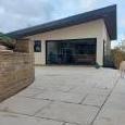
Why are scaffolders so difficult to deal with, my ex-scaffolder took to texting me at 5:30 in a morning and demanding updates on progress. In the end I’ve shown him the door, mind you, I’ve had value for money out of him. In the future I’ll be using my own to finish off the few bits. So here’s the photo of the house without the scaffold. In the next couple of weeks we we start putting in the rest of the windows, the scaffold was in the way previously, making it difficult to handle the largest 5 doors weighing 250kg each.1 point
-
We’d just like to say a great big thank you !! With all of your kind and generous donations, we can keep BuildHub advert free and continue operating for the benefit of all of the members. Your financial support is gratefully received and we would like to thank you for supporting us in continuing to grow and develop the forum. Financial support is not the only way that you can help us - if you can offer any skills that may assist with the support of the forum, please contact any of the FMG for details about how you can help with forum supporting services. BuildHub and the FMG would like to take this opportunity to say thank you for your ongoing help and support. Without your participation, this forum simply wouldn't exist. Thank you.1 point
-
We have a lot of roof and the only planning condition we have, is that we use local slate, 18 tonnes of it at a cost of £22k. So here’s the front roof of the house. And the rear roof of the house. A total of 18 separate roof planes in all! Why oh why did I let the architect talk me into this design? Once the Timber Frame company left a local roofer started to batten our the roofs for our random width, diminishing course roof. Everything was going swimmingly, however he complained of feeling dizzy whilst on the three storey section, so i sent him to the doctors. He’s very old school of farming stock and would probably be more comfortable going to the vets! The upshot is he was signed off sick and needed hospital tests. The doctor has told him no more roofs. So that’s it, he’s told me to find someone else! I’ve wished him a speedy recovery, he is a really nice local guy and I’m gutted for him as he’s no pension, so relies on local roofing and small building jobs. He’s irreplaceable, but somehow I had to find a replacement. If only I had a magic wand, I’d wave it for him. Gutted! Went to seek the advice of a neighbours regarding good local roofers. The upshot being, I’ve was told to hunt down a guy known locally as “Old Fruit”. I asked the neighbour “don’t you know his real name” the answer, “NO” I’ve only ever known him as Old Fruit” So I have no phone number and only a vague idea where he lives. As luck would have it, the third house I tried was Old Fruits parents house. So I now know he’s called Chris and having looked at the job and agreed an hourly rate, he’s start battening the roof out. Fast forward a couple of weeks and he’s back and this morning the slates started going on in the pouring rain, Old Fruit is keen to get on with the job! More to follow........1 point
-
@JSHarris next time you are this way call in and have a coffee and if you would like also take a look at the device installed and by all means a test of the water. Be very nice to meet you!1 point
-
The Timber Frame company arrived on site on a very wet mid-January morning. Very quickly wagon loads of components started to arrive and before long every space around the slab and up the drive was dotted with Ikea style flat packs, assorted timber and steelwork. The first job was to floor out over the basement to form a flat working platform for the main house erection. The original specification called for pre-stressed concrete floor panels, these were changed to Posi-joist, as this gave us space within the joist to locate services, ducting, electrics and waste etc. With the basement floor in place, the sole plate was positioned, levelled and fixed ready to attach the wall panels. With every panel, piece of timber, beam and noggin precut in the factory and numbered and with a full set of drawings, the house started to take shape quickly. Four weeks later and the roof timbers were in place and the next job is to fit the roof.1 point
-
Because our site was on a slope we always envisaged having a walk-in basement, that’s a basement surrounded on three sides by the slope and open at the front to a lawned area. The architect recommended a structural engineer to design the basement walls, what I hadn’t realised until it was too late, was that the design would be way over-engineered. His design is for a 200mm thick steel reinforced poured concrete wall tied into the basement slab. The slab and retaining wall contains about 52m3 of concrete and 3.5 tonnes of steel. The only saving grace is that it sits on an insulated raft designed by Hilliard Tanner and has UFH pipes cast into the concrete. So here we are just about to start pumping the concrete into the insulated slab. Next, the ICF basement walls were put together, a bit like Lego. Here you can see the completed walls braced and ready to receive 26m3 of concrete. Finally, the lounge section of our insulated raft foundation was done to complete the three-stage foundation project. In this photo, you can see the insulated raft and its steel ring beam under construction.1 point
-
1. Are the company's claims proven? Absolutely and unequivocally not. I can find no hard, independent, peer-reviewed evidence at all to support their claims. 2. Should we allow companies to be members of our forum? Yes, as long as they don't openly promote their products or seek to gather data from forum members to assist in marketing their products. Any company entering into a discussion on an open public forum knows before they start that open debate is a double edged sword, that can cause them reputational harm as well as reputational enhancement. An old acquaintance of mine, who was a kit aircraft supplier (I was once involved in kit aircraft design and manufacture) refused to join any aviation forum using his real name, or reveal any association with his company, solely because he felt that any customers who had experienced problems would raise them with him publicly, rather than privately, when seeking resolution. He felt, rightly or wrongly, that contented customers would, in the main, keep quiet, and as a consequence only the occasional problem would get a public airing. I'm inclined to think he was right, on balance. People are often quick to seek out forums and social media in order to complain, but far less motivated to do so in order to just say they had good, or acceptable, service, so the overall impression given can easily be very biased.1 point


This leaderboard is set to London/GMT+01:00