Leaderboard


Popular Content
Showing content with the highest reputation on 02/06/24 in all areas
-
You need to watch the lining for twisting Al’so I normally tack a diagonal string either corner and fix once they touch in the center2 points
-
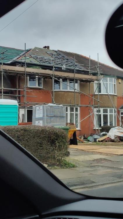
Installation Update So as my previous post had mentioned, I ended up going down the MCS approved route. After starting the installation yesterday then getting hit by heavy rain today, the install team are picking back up next week to finish everything off. I've not actually seen the progress with my own eyes yet as I'm living off site, however I've attached a photo sent to me by my Missus who passed in her car after the first day. So what did I end up with? 8x Black 420w PV panels (mounted 'in-roof') 3.6kW Hybrid invertor 8.2kWh battery Including the paperwork, registering and fitting it cost me just shy of £10k. **Insert Gasp Here** Yeah, I made that noise too. Although we've not finished the installation yet, let me just explain a few reasons why I went down this route and what I'd do if I did it again in the future. In the end I was hit by 2 storms during our build whilst already 2 months behind schedule. To make matters worse the roof installation got pushed along so much that it was split in half by the festive period with absolutely dire weather on top of the storms. My original plan was for my roofer to install the trays and for myself (with my electricians help) to install the panels. My electrician would then crack on with the other parts of the install that are inside the house. The problem is the timelines were all completely knocked out of sync. I didn't have the time to do my part due to work commitments and my electrician isn't due for another week on site. The roof, while exposed and not even felted yet, was then battered in the storms (A bit of wood nearly speared itself through my neighbours car!). So, I was forced to get a company involved which removed the burden from my other tradesmen who were already quite literally under the weather. Would I do it differently? Absolutely. Yes. I've still got a sour taste in my mouth because I'd have been able to save around £3k from my calculations if I was to do it all myself. I'd have then used that money to install a immersion tank to pre-warm water going through my boiler and reduce my gas bills (something I've planned space in for as a future upgrade). It was a tough pill to swallow going down this route but we're nearly there now I suppose! Hopefully these posts help others in the future much like everyone's replies have helped me. If I remember, I'll be back with an update once the system is all up and running to give any final verdicts!
 2 points
 -
i think it will be fine over the actual osb but not the joins if the are not flush. shame she didnt use that expanding pva glue. all of my vinyl flooring is suck down around the edges only with double sided tape, on the concrete flooring they sprayed some spray glue down first. just push it into the edges with a blunt bolster chisel or some thin wood and it creases it, then cut with sharp knife.2 points
-
Scraps of ply to spread the load 🤷♂️1 point
-
It's in a 92mm metal frame partition (2 doorways under a beam). I've used the double track and c-stud detail attached for the lintel which is good. I added a 3x1 timber in the lower track so that should allow the door lining to be screwed to the lintel. I've adopted the attachment approach of the Siniat image (folding down the vertical stud). I haven't done so yet, but may add small c-stud sections to the upper track as Metsec suggest.

.png.5335e8169bdc2ac8ee36642a545d82ec.png) 1 point
1 point -
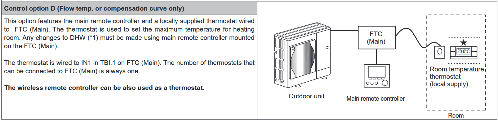
Try if you can to trace that cable back to the FTC6. I think these should go into TBI as that's where the inputs go, but these also depend on the DIP swtich settings. Although dealing with an earlier version, here is a thread I found that could be very helpful to read and it's about the same connections. I would also look at all your setting as even on weather comp. zones flow temps can be set to 60C I believe.1 point
-
The reason I ultimately went with the Graf is because the guy that did our groundswork has installed every type available up here in Perthshire. When he built his own house he went with the Graf. He liked the ease of install and he hadn’t heard of any of the number he’s installed ever have a problem. I also like the simple design and the easy access remote blower. All the blower type are relatively simple things though.1 point
-
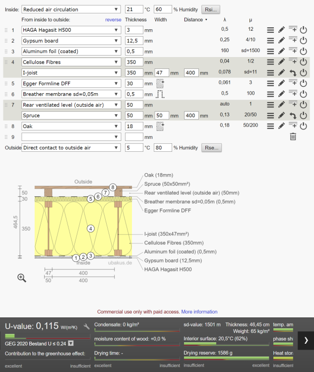
You only need to put a Service void where you are running plumbing, and in those cases there's often another option, ie within cabinets, or false walls hiding a concealed system, or within bath enclosures, or...etc. etc. Suitably rated electrics can run within the insulated wall/roof. So you could be at 465mm for a very high performing wall/roof structure. You could go 50mm less on the I-Joist / insulation and still meet PassivHaus targets.
 1 point
 -
Absolutely not The last time I saw a brickie on a none private site driving a tele handler was Never Unlikely to see them using a dumper I would never hire one on a self build and hand the keys to a brickie or anyone else If there’s an accident It’s YOU who’s is responsible1 point
-
With all these things I find it better to dry lay first. How was the OSB jointed or did the sheet cover they whole area?1 point
-
I would go with 6mm plywood, which is the normal spec for prepping floor for Vinyl, this even goes if laying on chipboard - usually recommended to be screwed down at 150mm x 150mm squares and 100mm centres along the edges. As for adhesive, she could just order some spray vinyl adhesive like this random link: https://www.best4flooring.co.uk/vinyl-spray-adhesive. Bostik also sell tubs of vinyl floor adhesive that might be a bit cheaper. Last time I paid for an installer to do a vinyl floor for me he even filled and sanded over the screws and joins between plywood sheets and achieved a very good finish.1 point
-
Can she add some hardboard over the OSB, and that will get rid of any worries and give a much better surface to adhere to.1 point
-
OK having talked to a flooring manufacturer and getting to the tech dept i am now happy that stick down is the way to go thwe 27c that all makers quote is a max temp for direct heat and not becasue of tile lifting as the adhesive will be fine ,but discolouration of the tiles . In the most extreme cases he told me you could end up with faded lines in tiles where the heating pipes run , also flooring to go behind bifolds,conservatories etc they do not reccomand clickfit type only stick down type so that me happy that there should be no problems proviiding the pipes are well buired in the screed and not close to surface I got the impression it was more a problem with retro fit electric heating panels I did a wee test on my floor in this house --raised room temp to 24c and with input of 39c --floor never exceeded 24.5c whikle it was getting up to temp -- so no problem1 point
-
i would suggest following the MI for whichever STP you go for.1 point
-
Is this the drill ? It has hammer mode. Make sure you buy "quality" Masonry drill bits... and it should drill thought most materials up to 10mm no problem
 1 point
 -
Velux windows are designed to work with or without counter battens.1 point
-
Is it needed at all? Bco probably but they may reasonably say that it is specialist. Likewise SE may not have studied this but probably has. I know because i studied it as designer and contractor and found how little it is understood. Spec help will come from a manufacturer. My favourite is Envirograf, then do them the credit of using their product. It is a matter of the exposed surface area and the mass of steel. Heated perimeter÷area. How chunky basically.1 point
-
Haven't had it checked. But the daily readings from the supplier are close to what I get from my own monitor so I have never felt to call them into question.1 point
-
Your drill is an SDS (Slotted Drive Shaft, or SDS +) drill , and the drill bit is SDS rated ? And the drill is set on hammer ? And the drill bit is new, and clean? First hole (pilot hole) about 4mm or so. Then drill out to 6.5mm (if necessary). Drill the hole 10mm deeper than needed Hoover, hole, suck (or blow out -eyes- , care) Use 6.5mm concrete screws to attach (whatever you want) to the wall . Countersink the hole and hide the screwhead with a wood plug. YT is your friend - here's a playlist https://www.youtube.com/results?search_query=sds+drill+vs+hammer+drill1 point
-
For a full wet room I would always use r11 But showers and bathrooms are fine with r101 point
-
You need counter battens if you have sarking, but a tented membrane draped across the rafters doesn't.1 point
-
My install - not that detailed but you’ll get the general gist.1 point
-
And they really can float upwards. Years ago I was working in the Daventry area of Northants and a colleague came back into the office and told us all that we ought to see the "submarine" on a building plot in a local village. Passing that way over the next few days (I think we all did that route) there was a large cesspool tank that had forced itself back out of the ground and stood like something Jaques Cousteau would use for all the world to see. More concrete and partial filling with water to ballast it was called for.1 point
-
Same with ours. 250kg slid off trailer ramp. Easy.1 point
-
Yes - guilty as charged1 point
-
six pages ofr detail for second part of course with some provisions -- like cost for bathrooms and skitchen -- estimated costs put inehich i can supply own goods for , same goes for ligth fittings etc seems a good way to me1 point
-
+1, some people laughed at my quotes because they were like war and peace but I hate ambiguity and I never had a problem with customers misunderstanding what was included In the price.1 point
-
Hi George, i have a very kind offer via PM to do the very same thing but thank you. I do suspect that the scenario that you propose is exactly what i did. But as i have made 2 failed attempts to submit already i am clearly not the person to find the error and correct it.1 point
-
This is just a terminology issue. That's not underpinning ... that is forming a backfilled opening for a service penetration. There, problem solved. Underpinning is, correctly, a method to improve the load bearing capacity of foundation by increasing the foundation depth, width or both. You're not doing that, so it isn't underpinning. It just looks like underpinning.1 point
-
Vacuum is best. In reality, when you look at the numbers, there is not much in the normal range of insulation and other losses will soon dominate. Material Thermal conductivity [W·m−1·K−1] Notes Silica aerogel 0.02 Polyurethane foam 0.03 Expanded polystyrene 0.033–0.046 Fiberglass or foam-glass 0.0451 point
-
The effectiveness of insulation depends mostly on.. a) The thermal conductivity of the raw material it's made from. Lower is better. b) The thickness. Pure Aerogel has the lowest thermal conductivity but in it's raw form it's very fragile and expensive so it's not normally used except perhaps on spacecraft. Usually it's in a different form like a blanket and these have a higher thermal conductivity. Beware sellers quoting the thermal conductivity of raw Aerogel in adverts. Compare with the actual specification of the prouct. Post the numbers including the units of any product you are looking at and someone might be able to comment. Next best is probably something like a PIR based foil covered foam. Typical all insulation products have thermal conductivities that vary by perhaps 30% so none can be 1/10 the thickness of another and have the same performance. Beware some manufacturers quote U-values for their product when installed with an air gap. Anyone can make their product look better by requiring an air gap. I'm currently on a train in India so might not be able to reply. Family are at home so it's not a risk me posting this.1 point
-
Thank you everyone, your replies have put my mind at ease somewhat, and are much appreciated. We will of course be coating the steels with intumescent paint, then a top coat to complement the rest of the interior. All the steels sit inside the thermal envelope, aside from penetrating the floor to the footings. I’ve had standoff ears welded to the uprights to accommodate the IWI, plasterboard and finish thickness. Hoping it all works out!1 point
-
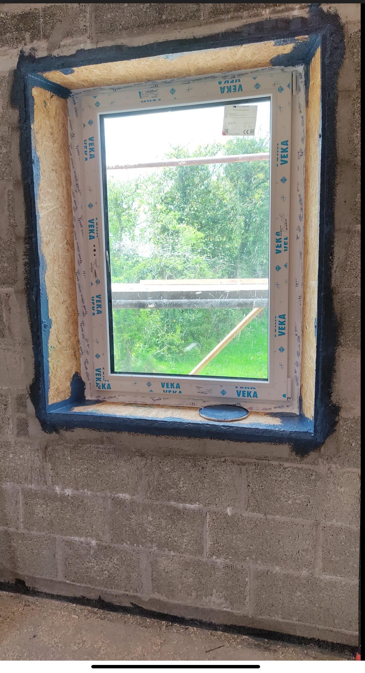
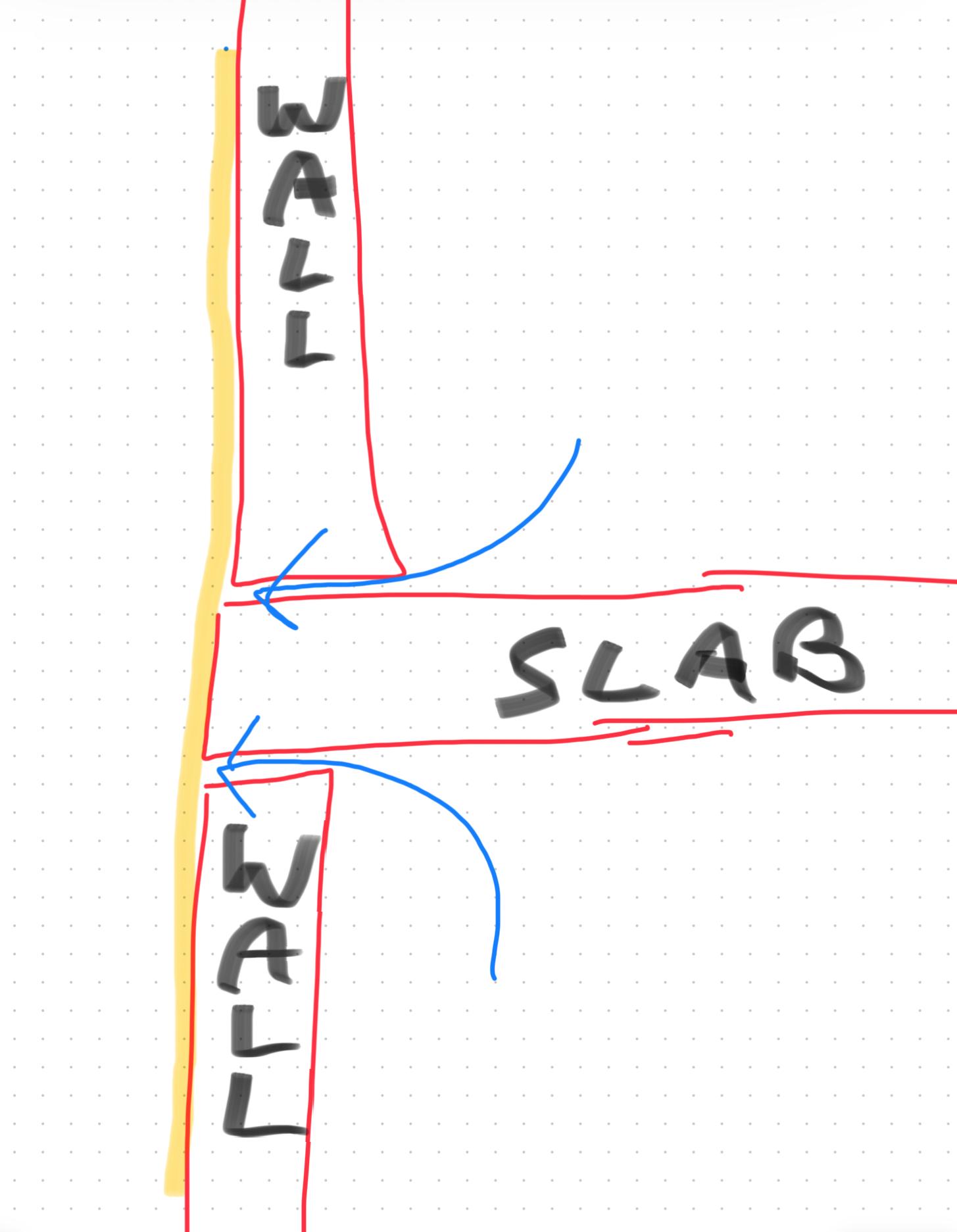
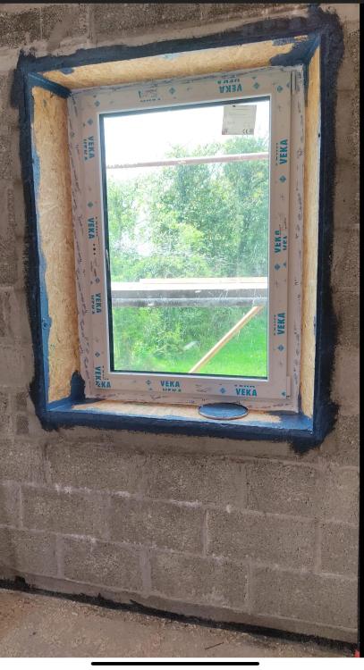
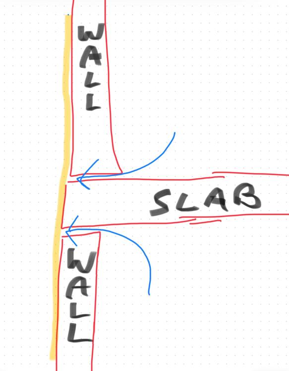
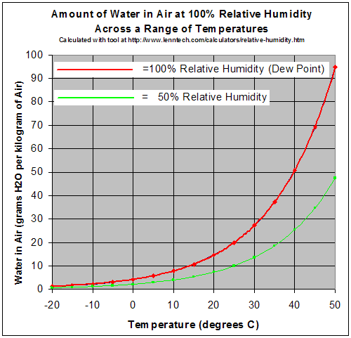
Sure. Vapour needs a surface to condense onto, like a bathroom mirror. If there was an unbroken airpath under and over the slab then it could have moved un hindered until it met the cold back side of the render. Normally done to join two parts of a house together to prevent air leaks at the interface. It's best done with some permanently elastic material like airtightness tape or paint to accommodate any movement. Walls to floors. walls to ceilings, walls to windows etc. the idea is to create a completely airtight seal. Here is how I did our windows and floor. I filled all large gaps with sand and cement mortar and then painted on blue airtightness paint which dried to black. Tape was used to seal the OSB window boxes to the window frame. (For anyone who's interested we used a parge coat first near the floor and around the window to save using up too much expensive airtightness paint). Have you any actual measurements of the bedroom relative humidity? Air tends to equalise pretty well in a house with open doors. You can pick up a cheap hygrometer for less than €10? I'm working on a best guess here. Do you have internal photos too? Was it ok before the Evertex? Has the wall been mechanically stressed regularly , for instance by a football? Over a 1m distance with 50° of temperature difference they will differentially expand by less than 0.3 mm. Assuming the interior of the house is at a relatively stable temperature then maybe the outer 50-100mm might be subject these variations over a year. In any case the differential movement would be 0.01-0.03mm. About the width of a hair, hardly significant. The air leakage is the vapour heavy air from inside making its way to the outside via air paths. Its the absolute humidity you need to think about although its hard to measure so the relative humidity is often used. Relative humidity is temperature dependant though so external air at 100%RH and say 10° actually has less moisture than internal air at 20° and 50%RH. Do you have a mechanical ventilation system? Pictures please. in good light, close and wide shots. Theres no point in finding any products until you really nail what caused the issue initially in my view. Yes if it is stripped back to the bare surface first. However you would still have moisture trapped behind it. I would hold fire on any purchases for now. The moisture that caused the issue originated (i think) from inside. However when this damaged the render then the rain was able to damage it further. I think Ireland is just too wet to consider materials like lime render unless you are prepared to constantly maintain it. Thats why almost all houses here have sand and cement over a block rain screen. It's just so massively moisture tolerant. Its no different from a ventilated metal rainscreen, or timber or fiber cement. Although in a cavity wall it does contribute to the structure it's primary function is to keep the rain off the inner wall.
 1 point
 -
Just approach a local timber merchant as they will almost always have machinery to both cut and machine profiles to your needs.1 point
-
Assume 100mm cavity? Then greyEPS bonded beads, job done.1 point
-
Forget the footings, how are you separating it from the cavity or the outside. don’t have it on show it will look shit, it’s not an old 1860 factory your converting. insulate it then board it. I was going to have a huge steel in the ceiling exposed, was even looking for fake rivet heads to glue on, we boarded it and painted it, I don’t know what we were thinking.1 point
-
My corresponding as designed figures are around 0.12 for the first three and IIRC 0.9 for the last. As I discussed on some of my blog posts, the total heat loss from air exchange is about a quarter of that that of the combined loss from the walls, roof and windows, but that is because I have an airtight house (~ 0.5 ACH) and MVHR. But this would not be the case with a leaky house built to typical 2008 air-tightness standards and no heat recovery. This would increase this element of the pie maybe 5-fold and would become the biggest single source of heat loss. Do the quick check, eg. a JSH style spreadsheet of Σ A×U×Δt, to get the as-designed heat loss, but I suspect that your losses are so high because: The as-built performance is nowhere near as good as the as-designed spec. IMO, most builders are often very slapdash if not under tight quality supervision. It's just that their general ethos does value good thermal performance. Jeremy Harris once did a walk-around a new estate near his house (on a very cold Feb evening IIRC) with a decent FIR thermal imager and there were whole wall and areas of roofing with missing insulation, major leaks and hot spots around fenestration, etc. It is very leaky so your air-exchange losses are significant. That's why I suggested you borrow rent or buy a FLIR add-on for your mobile or even buy a cheap spot IR thermometer. Work out why your house is leaking heat like a sieve first before spending 10s £K on getting a more efficient way to generate that wasted heat.1 point
-
Not that, just seemed an odd thing to do. By quoting properly, everyone can see it, and who it was from/to and the original poster gets notified, so they get a chance to answer or clarify.1 point
-
TL;DR I suspect that you don't have much insulation under your floors and the flow temperature though the UFH is set too high to compensate. Jersey has a very similar climate to where I am (Cornwall), so luckily you don't have a long heating season (mine is almost over), so better thermal management may pay dividends i.e. more selective timing of when the heating is on. The physics of heat loss is really quite simple, but often made to look difficult. Basically changing a heating system does not change how much energy the house uses, though a heat pump may, if designed correctly, reduce the amount you import/pay. The British have got too used to heating systems that blast out heat at a great rate, warm the house up, then let it cool down, then blast out heat again. While this may seem to be an effective method, what is actually happening is that there is a cycle of constant over heating and over cooling, it is like driving in Jersey, either accelerating or braking, never cruising. Now for some terminology clarification. kW, not Kw, or KW or kw, or even killer what, is the power of your system. kWh, not KWH, kWh, kw/h or killa wot our, is the energy. It is the power, multiplied by the time. Think of the power [kW] as how powerful your car engine is, and the energy [kWh] as how much fuel it uses]. Your 600 litre AVC is how large the fuel tank is. So your is really 100 kWh/day. 100 [kWh] / 24 [h] = 4.17 kW or at 0°C 5 kW Now as your house is 1800 square foot, which is really 167 m2, (keeping it all metric makes life easy) your heat load is 0.025 kW/m2, which is not dreadful, though on here we like to get below 0.010 kW/m2 [10 W/m2]. Mine is currently 0.011 W/m2, and apart from curing nearly all the bad air leaks, adding in some extra loft insulation and adding secondary glazing to my old timber frames double glazed units, makes my 1987 build pretty good. So what do to. Initially keep records i.e. internal and external temperatures, energy usage and behaviour patterns (if you are away or have extra people stay). See how much loft insulation you have and find out what is below your ground floor, insulation wise. Find and fix any leaky windows or doors, if there is a draught, cure it. Check how much heat is coming out of your water storage cylinders, this is easy to do with an infrared thermometer as you just check the cylinder external temperature and the the water temperature. You may find that the storage temperature is a lot higher than what is needed. Heat loss is not linear, but hopefully most of that energy goes into the house anyway this time of year. Sketch up your house, with dimensions, and work out where the greatest heat losses are i.e. though walls, windows, floor, air leaks etc as that will show the best place to spend your money. As an example, the few cheap changes I did means I now us almost a quarter of the energy I used to when I first moved in. A heat pump, of any sort, should reduce the amount of imported energy, but there are some caveats. They have to be sized correctly for the heat load of the building, the power delivery, as a multiplier of the power in, is very sensitive to temperature differences. The smaller the temperature differences between outside and inside temperature AND between the inside temperature and the heat emitter (UFH in your case) temperature. This is why they are designed to match the most likely range of temperatures during the heating system i.e. 21°C inside, 8°C outside, emitter temperature >30°C. An air to air heat pump (A2AHP) is a good choice initially and there are some cheap units that can be easily installed. May be worth fitting one in the main living area as an experiment (a few people on here have a lot more experience and have fitted their own). Also worth remembering that your new house has a much larger exposed wall area, and probably much larger window area, but again, this is not the whole story as volume to exposed area ratio makes a difference, smaller houses have a worse ratio than larger ones (generally), bungalows are worse still (lots of floor and ceiling). And never trust sales people and most plumbers, very few will have studied thermodynamics at university.1 point
-
If you are using ~120 kWh per per day heating a ~180 m2 house at ~0°C, then it has 3-4 times the rate of heat loss compared to my house which is a bit larger and which we maintain at about 23°C. OK ours has a near passive design, but it still seems as if it has been built to a poor insulation standard especially for a 2008 build which if build to code would include 100mm insulation in the walls and some form of insulation under the slab. I would be tempted to get a remote FIR sensor and camera and do a survey inside and out to see if there are any quick wins that you can do to improve the general thermal performance. Example include: Missing or poor insulation and cold bridges. Some remediation might be possible, especially in roof voids. Bad air leaks and air circulation behind dot and dab plaster boarding Poor window performance. The challenge is that fixing these during build is cheap and easy so long as you have decent on-site inspection, but doing so in retrospect is a lot more problematic and can be costly. Whilst ASPH installations aren't cheap (as you know I can't make the numbers work for me and I designed my house to be ASHP ready). The 3kW A2A units are pretty cheap and you should be able to get one or two installed at around £1K ea. These have a CoP of around 3 and can also be used for cooling in the summer. They aren't a complete solution as they can be quite noisy, but they can dump heat into the house interior quite cheaply. At some point a ToU (Time of Use) tariff option might become available which will allow you to shift heating to cheaper ToD (Time of Day) rates. This will give you a grater ripple on room temperatures, but using in-room heating (e.g. I use an oil-filled electric rad connected to a smart socket in the living room). This is at a CoP of 1 (the same as your electric UFH) but more responsive and localised to the rooms that you are sitting in. PS. use the @name trick if you want to notify a member about your post.🙂1 point
-
Let me start by saying an electric boiler is the most useless invention man has ever made. IF you are going to use direct electric resistance heating you are better off just with panel heaters and an immersion heater. Putting a big heater in a box on the wall and using water to move the heat around that will never make it more efficient. However it has given you wet under floor heating so that might be useful. No 1, separate out your space heating and hot water heating, before you can go anywhere you need to know what is using what. If it were me I would be fitting an electricity meter on the feed to the boiler, setting heating and hot water times differently NEVER on at the same time and taking lots of readings to see how much the HW and heating are using separately. How good are you at DIY? With help from this forum would you consider DIY fitting an ASHP? I have no idea what the regs are on Jersey but the parts are likely to cost no more than £5K and DIY might make it viable. You might be better off just with a good plumber and electrician that you can trust, and who are capable of reading an instruction manual, rather than a "specialist" heat pump company which is what I suspect you have been talking to? Do you know anything about the building construction, what levels of insulation for example, particularly under the floor? And what temperature is your UFH running at the moment?1 point
-
I'm not sure where to start unravelling a system like that but if it was my house I'd be looking at installing an Air to Air system for the main rooms, plug in heaters on a smart timer for the bedrooms, see what is the cheapest way to heat hot water with the system you have & if you can disable all the underfloor stuff and get some Solar PV going, the cheapest way how to help offset the Electric costs a bit. Youtube channel EV Puzzle has some info on Air to Air & oil rads on a smart timer. At least it's an option if the current system is dimming all the lights on the Island?! Hopefully more knowledgeable chaps on here will have better suggestions shortly.....1 point
-
yes I have had an experience with the shower power booster pump, worth the money I would say. It was the main brand of booster pump that I had heard of when shopping around, maybe see if you can get it any cheaper somewhere else? also if you're not sure about installation ask a plumber you don't want to create more issues1 point
-
Cut off with a disk cutter - That's what I had to do in the void underneath my suspended floor - the clay pipe was cracked (probably from when the house was built - was never going to be found till I went under the floor to insulate the pipes and between the joists) 40 years of a small leak wasn't a nice area to work in although suprisingly not smelly!!!1 point
-
Good for you. There is lots to learn, but if your approach it in the right way it can be great fun, personally and financially rewarding. Have you had a look at your permittted development rights? You probably have but that is a good starting point. Even if you don't comply they help you identify where you don't and that leads you to the next step as to what you need to do to remain compliant with the regulations. Where are you in the UK as PD rights differ.1 point
-
Everything kicked off on January 8th 2024 finally after 8 years of faffing about and trying to line up finances, finding someone to sign off building regs and a year of selling the old house eventually succeeded. There was about 120 tons of muckaway judging from the number of trucks. The guys brought a 17 tonne digger and were glad of it. The big roller they didn't use in the end but went with a more compact diesel unit. hardcore was added and leveled. The trickier element was getting a rainwater harvesting tank installed. It had to go at the back of the site before we could block it off with the next phase of works. I found the office staff didn't have a clue about the dimensions so how deep to dig the hole?! They did the next best thing and sent a guy out to the yard with a tape measure and I passed these info on. The crane used was impressive - 350K worth to move a 4.5tonne concrete tank into position. They then crawled inside it to commission the pump etc and seal it up until the next phase of adding power (need to drill a hold into the tank but they provided enough electrical cable to go back to the house to hook it up later. It holds 4,000 litres and needed balast to stop it shifting as even at that weight it can move around!! Got a hose and friendly neighbours to assist and half filled it up!! Only 1 complainer - a neighbour around the corner giving out when the flatbed dropped off the excavator, there's always one! Did get a site inspection the next day but only to confirm we'd started within the terms of our commencement notice I think and he seemed friendly anyway! I left the mortgage a bit late, still waiting on approval so am spending cash currently. Hopefully that comes in this week! The Timber Frame prep is starting in their factory - I think I'll be ready in 5 weeks or so or on March 1st. Onto the exciting portion - Foundation Screws, 1.5 meter long and will have a 300mm x 300mm plate bolted to the top of the screw head. They spend an entire day prepping the holes, measuring and remeasuring to ensure everything was fine. There was some confusion around the height the screw was to end up but the groundworks team had marking the fence panel and I put them in direct contract with each other and didn't hear a peep from that point. All was good. I was hearing 100mm differences in the levels one day and this changed to 2mm the next!! I was sick with flu so not being able to be onsite was a curse, you just have to hope it works out. They pre drilled down to break up some rock but nothing too severe. The delivery took a bit longer than expected, so they started later than I'd hope which means I lose the groundsworks team for a week at the start of February but what can you do. Some start when they say, others, well, it's a moving target!! But once they started they've been onsite every day despite the cold weather and are making good progress. There are 89 of these to be driven in to a level set by the laser. They use an electric motor to drive in the screw with an arm braced against a previous screw they leave half way up. Eventually all you'll see is a field of square plates. A raft is to be poured around these and the Kore passive raft is being delivered to site later this week for use next month. Yep, there's a second raft going in on top of the Kore - like a Kore Concrete Raft Burger!! Enjoy the photos!1 point
-
Well done you for giving this a go.. If you want I can give you a few pointers on what you need to do to get the preliminary sizes for you timber frame (TF) and the grades of timber you may need. To do that I would need to know.. A: The floor plan dimensions, location of the internal load bearing walls roof pitch and need to know about any funny loads you are introducing.. pool tables ect.. B: The ground, first and second floor levels. C :The sizes of the openings.. windows and doors. D : Your post code so I can assess the wind and snow loading. I'm minded to give this a go with my SE hat on as.. 1/ You have made a good effort. 2/ It may help other folk on BH understand what goes into the preliminary sizing of a timber frame.1 point
-
Hi all. I don't think this is safe for the following reasons. Mind you you can ask ten SE's and you'll get ten different answers.. here are my thoughts. Agree that the ledger distributes the load over a number of the fixings. Mainly to account for a few badly installed ones. Also agree that if you use EPS or foam 200 you will get initially nominal tension in the anchors (as the say load increases due to snow) as the EPS will compress as the ledger rotates (and the fixings start to bend) due to the added eccentricity of the load. If the ledger was hard against the wall, it was 50 mm thick and with joist hangers then the eccentricity would be would be 50mm, maybe a bit less if the hangers are of wrap over type.. If you put a compressible insulation behind the ledger the eccentricity is now doubled to roughly 100mm and this completely changes the behavoir of the connection in a dramatic way. The insulation is not strong enough to deal with the forces until it compresses by a long way and by that time other things will fail.. probably suddenly which is dangerous. An EPS or Compacfoam 200 insulation means that it will often carry a load of 200 kN/m^2 at 10% compression.. thus before it can carry that much compressive load it needs to compress by 50 x 10% = 5.0mm and by that time your ledger will have rotated a lot and dropped a bit. All the bending forces will by that time get transferred to the fixing which is into brittle masonry. The fixing will now be subject to the same downwards loads (call these vertical shear forces) but also a significant bending force due to the compressible nature of the insulation. This causes the masonry to not least crush as the fixing enters the wall and that can reduce the capacity of the fixing by more than 50%. I have only touched here on some of the basics.. the behavoir of these types of stand off connections is much more complex and you enter into this world at your peril. I think your starting point here is to get a feel for the difference in load capacity of a fixing with a stand off (which is what you have) is to go to the Hilti website and see how much difference it makes when you have a a column base plate set above say a concrete pad stone. You can see this often on lighting standards next to motorways / railways where you can see the column base plates set above the bases with the bolts exposed.. you have something similar. Now even navigating the Hilti or similar site and interpreting the load data is going to take a lot of knowledge, but just have a look.. they have some pretty user friendly diagrams. I hope you'll then see the big load capacity reduction and realise that what you are proposing is not safe unless you design for the completely diiferent behavoir. However there is often more to this than meets the eye. When we design a building we want to tie different bits together for overall stability. In your case this could mean that we want to tie the rafters back to other parts of the house so the whole thing acts as a oner rather than individual elements.. we call this as SE's not least robustness (if one bit fails the rest hangs in there) and look at alternative load paths. We think.. just say the builder cocks that bit up.. is there another way the building can hang in there before it falls down? So rather than pushing the connections to the limit we need to introduce a bit of redundancy to account for human and material error. In principle you could make you thermal break using say something like this https://www.armatherm.co.uk/thermal-break-materials/armatherm-frr/.. I think it is a waste of money.. just accept you have a bit of a cold bridge and beef up insulation elsewhere to compensate. Also remember that you are fixing into old masonry, maybe bricks with holes in them, for the fixings to work well they need to be away from the mortar beds etc.. you are asking too much here.. in theory it may work but can you build it in real life and make it safe? So to conclude my thoughts are DON'T do this. Fit the ledger against the wall, maybe with a DPC behind.1 point
-
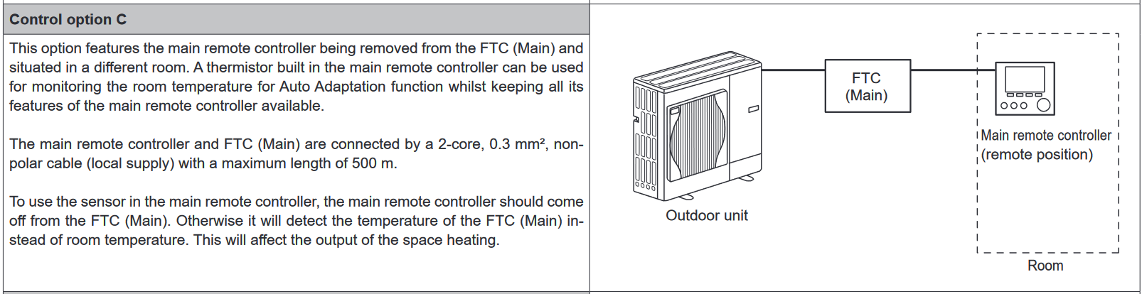
Just adding to this as I've had the exact same question (UH8 + ecodan FTC6) and managed to figure out the answer. My installer had left the ASHP configured with SW 2-1 set to ON but nothing connected to IN1 (TBI.1 7-8) with the plan being that I'd connect the demand from the UH8 once I had all of that wired up. Obviously, the heating worked just fine even without a thermostat being connected to IN1 so I wondered why anything would change once the UH8 demand was actually connected up to the FTC6 IN1. A closer look at the FTC6 manual provides the answer. Without any external thermostat input, the system operates according to "Option C": In my case, the remote controller was set to "Auto Adaptation" mode where it uses the thermistor built into the remote contoller itself to provide the "thermostat" function for the FTC - ignoring anything connected to IN1. To actually make use of the demand signal from the UH8, the controller mode must be set to either "Flow temp." or "Compensation Curve" according to the manual (Option D): In my case, I've opted to go for the "compensation curve" option and can see the ASHP turning ON/OFF in accordance with the demand signal from the UH8. I think it's essential that the operating mode of the FTC remote controller is changed from "auto adaptation" as soon as the UH8 and actuators are installed since I can envision a scenario where the ASHP eats up energy without actually providing any heating. This might happen if the remote controller is set to a higher temperature than the stats? The stats will shut off the UFH circuits once they reach target temperature but the remote controller (in auto adaptation mode) will keep running the ASHP trying to reach the higher temperature set in the remote controller. But of course this will never be achieved since the stats have already shut off the circuits .... NOTE: The FTC6 manual states that the ON/OFF cycle time of the thermostat must be 10 minutes or more to prevent damage to the compressor; however, by default the neoStat v2/Polypipe UFHSMARTW "delay start" function is set to 0 minutes (immediate). To remove any possibility of short cycling, I've increased this to 12 minute on my stats.
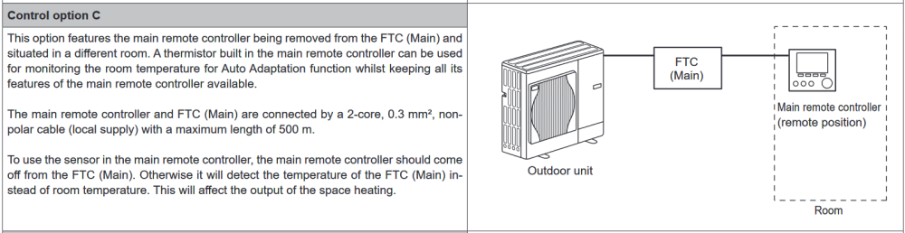
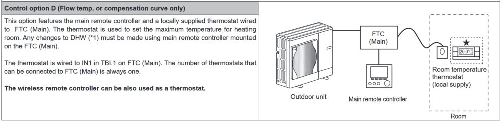 1 point
 -
If you avoid switching multiple loads on at once there's a fair chance you'll be able to stay under 3.68 kw for most of the time, but it can take a while to get into the swing of not switching everything on at once- 18 months for my wife to sort of get it!!0 points