Leaderboard

.jpg.c21f3ac78c9b7efd90cbdcb312744dc5.thumb.jpg.7adcad4c0e384f5ecd7d56b0618df6e5.jpg)
Popular Content
Showing content with the highest reputation on 03/05/20 in all areas
-
Just to confirm on this. I spoke to HMRC some months back and explained that I was having a battery storage system installed as part of the building's systems, connected up to the PV array. HMRC confirmed that although the PV system and the battery system came from different suppliers/installers, as it was all part of the building's power system, I can claim back the VAT on the batteries.4 points
-
Background I've blogged and posted separately about how I currently control my Underfloor Heating (UFH) and Hot Water (HW) systems using a Raspberry Pi (RPi) computer. This takes input from some digital thermometers, and a couple of digital flow meters (mainly for flow logging) as well as Met office weather forecast data to calculate timings and to switch the power circuits for my Willis heater, the circulating pump and the supply to my two SunAmp PV units. The initial design choices in my current implementation were to minimise my own learning curve and to mitigate the development risks for me. For example, I was already one of main the developers of an ESP firmware platform, so it was just easier for me to use a couple of ESP modules to handle all of the external sensor and relay control. That being said, this latest COVID-19 outbreak underlines our need to have a practical fallback for Jan. As it happens, both my son and son-in-law work in the IT industry, and both use RPi based home automation systems in their own homes, so either could in principle take over maintenance of our RPi-based system if necessary. Even so, on reflection my system setup is more complicated than it needs to be. In particular neither Rob nor Andrew is familiar with the ESP module firmware and development system, so this subsystem is not something that I could easily hand over. Given that a single RPi could do the entire computer lot quite comfortably, I am now considering dumping the ESPs entirely and slimming down the software stack on this RPi to that only needed to run the CH and HW control. This topic discusses possible approaches to such an RPi-based control system that meets my needs but once documented could also form the basis of an implementation for others. What I am proposing is to do this in two passes: first more a review and discussion cycle, where input and comment from the likes of @Jeremy Harris, @PeterW, @Ed Davies, @MikeSharp01, @ProDave and anyone else who feels that they can make suggestions and give feedback; the second will be a set of blog posts where I write the entire system up in detail. Switching the power circuits I use Solid State Relays (SSRs) to switch the power circuits for my UFH and HW. All power SSRs pretty much all work the same way, and if you want to know more then Big Clive gives a good tear-down / explanation (here) on YouTube. The CKRD2420 modules that I use can take standard (5V) digital inputs and turn on the power side at the next AC zero-crossing (that is with a delay of up to 10 mSec) if the input goes high. These CKRD2420 modules currently retail at ~ £40 each (compared to the £5 ones that Clive reviewed), but this is the premium for a decent quality approved module from a reputable supplier, and ones that my electrician was willing to sign-of on as part of his 240V installation. The Crydom CKR24 Series Datasheet gives their operation parameters: the input side requires a 4V DC minimum on voltage at up to 12 mA to power the SSR internal opto diode, and power-side TRIACs can drive both resistive loads safely and reliably. This 4V minimum exceeds the general purpose digital outputs of 3.3V based RPis, so some form of voltage / current conditioning is needed to control these SSRs, though the input side of each SSR is already opto-isolated from any transients, it is pretty straightforward to boost each GPIO output to 5V and capable of providing a sustained 15 mA. I prefer to keep my discrete components to a minimum, so a good approach is to use a SN7407N hex buffer driver which can drive up to 6 GPIOs from a single 16-pin DIP package. Note that these buffer outputs are open collector and are driven to 0V when the input GPIO is driven low. The SSR input is connected to the buffer output and 5V, and hence the SSR is on when the GPIO is low. When the input GPIO is high, the buffer output floats and is pulled to 5V using an external 4K7 pull-up resistor on each output, giving a 5V + 5V input to the SSR, that is a 0V difference and switches it off. Note that I previously used an I²C-based port extender instead of a hex buffer driver on my ESP8266 implementation because I had less free GPIOs, however the RPi has a lot of available I/O pins so using these allows me to avoid MCP23008 I²C driver and to simplify the RPi software. One aspect that we do need to careful about is the default state of the relays at power on and before any active software control is initiated. All GPIOs are initiated as inputs, with GPIO 0-8 having pull-ups to 3V3 enabled and GPIO 9-27 pull-downs to 0V enabled. Given that we want any SSRs to default to off at power-on, we need to connect any SN7407N inputs to GPIOs 0-8. The other design issue to note here is that the power TRIACs within the SSR are not 100% efficient; they dump roughly half a percent of the switched power as waste heat, and so will generate roughly 15W of heat per SSR when powering a 3kW circuit. Any enclosure will need to operate within safe temperature tolerances at N × 15W heat output and this will require some form of heat dump design. Collecting Thermometer Readings The digital thermometers are DS18B20s. These are accurate and cheap. You can string as many as need on a one-wire bus which only uses a single GPIO. This bus is fully supported by the RPi's Linux kernel drivers, so the implementation is easy. Hall-Effect Flow Meters These have a 3-wire connector: GND, 5V VCC and 0 / 5V pulse output. Each output needs to be conditioned to be read safely on a RPi GPIO pin but a a 4.7 KΩ + 10 KΩ resistance divider does this job fine. Note is that the Hall output is again open drain. To Follow Physical packaging Circuit designs Software options: native Python vs NodeRED The underlying physics Control regimes and options Anything else that people want to discuss3 points
-
I am staggered that your electrician can't or won't do this. It is just a radial circuit from the consumer unit to the inverter, with an ac isolator switch and a generation meter. And a DC isolator switch between the inverter and the panels. If your remote meter is in a decent cubicle it could remain there, mine is about 20 metres from the house. As for the PV diverter. That will have a current clamp on one of the meter tails. Even if the meter is still in the remote cabinet, that can be fitted in the house, as long as the external meter box does not feed off to other places, just the house. If like us, the external meter box feeds to other places, then the current clamp would have to go in the outside meter box. I provisioned for that by laying a length of spare SWA telephone cable to the meter box. Before you go any further I would choose which PV diverter you are going to use. Others will have to recommend one as I made my own. You will need to register the PV with your DNO and they will need a bit of paperwork, including a schematic of the instalation.2 points
-
I would extend the pipe up above the WC and fit the AAV there. There is a risk of sucking the water out of the basin trap when you flush the WC.2 points
-
Instead of piles of dirt for collecting you could do what we had to do in London, put a couple of skips where the dirt is to go, then when the grab lorry comes get him to empty the skips, and just refill them. this solves lots of problems, it saves muck getting washed onto the highway, keeping it all tidy and neighbours a bit happier, then as you finish just get the loaded skips removed. You are probably better off getting multiple trades in to do each bit if you get one company in and your site looks like an agro job they will do one of two things, not quote or price it very high. With multiple trades the bit they will do probably won’t seem too bad so they will do it move on and be thankful that they didn’t get asked to price all of it.2 points
-
The Apollo Gem is another one with a wireless sensor: https://www.apollosolarelectric.co.uk/products/ Has a 30m to 40m indoor wireless range, according to the spec.1 point
-
Really sorry to hear this, let me know if I can help out in any way. I have to take my hat off to MBC here, they were equally helpful when I had the render issue - sending Brendan to site for half a day to work with the contractor to get to the root of the issue two plus years after the house was built.1 point
-
Those photos are bringing back all sorts of nasty memories. You have my sympathy!1 point
-
This blog & video from Charlie Luxton shows leak testing on his flat roof (prior to green roof) - might be work looking at? https://www.homebuilding.co.uk/leak-testing-the-flat-roof/ He used Thornton Consultants https://thorntonconsulting.co.uk/ to test the membrane - but with consultant in their name they may be expensive!1 point
-
Thanks for all the comments so far. Here’s an update: MBC (Darren) came onsite as on another local job. (they are brilliant, those guys) And together we took out a load of soggy insulation and put a small hole in the lower roof deck. We still have more to do as haven’t found the edge of the wet insulation yet. Leak appears to be down a bit of OSB nailed onto a roof joist below the upstand of the roof light. OSB roof deck appears dry in that location. roof inspection yields nothing obvious. It’s hammering with rain so can’t test anything. A piece of plastic over what we thought might be the problem has not stopped the drips (every second when it is raining). Inspected roof light mastic seal as advised by them. No issues of note. And roof light overhang appears deep enough to prevent any water ingress. Awaiting roofers on site. Guess that might be tomorrow now. waiting on the insurance front so we can see which party is liable and whose insurance will pay up. luckily we own a scaffold tower (for our hedges, v helpful during the build) so put that back up pronto. @jack your story fills me with trepidation but I expect we’ll be down some similar route on timing. Got to get roofer to admit liability first so need to have a better go at leak location inside first. once it stops raining we can get back on the roof to properly test it. MBC and we agree this has been going on for months - the sodden insulation and lack of evidence of a failure point seems to indicate a tiny hole and slow damage. and to think we were thinking we were almost there ?1 point
-
75mm would be better. 100mm preferred. 50mm only gives you 1:120. Make sure it is properly supported with a bracket every metre.1 point
-
It was a verbal confirmation, but from their specialist team that deals with the DIY/self build area of VAT. I had to book the call and wait for a few days for a specialist to get back to me, so it wasn't one of the generalists who confirmed it.1 point
-
i may take up on that in the future.1 point
-
That was exactly what we had problems with. PM me if you want to discuss.1 point
-
Exactly this. Took us nearly a year from start to finish. Two rooms were affected. In our case, it was due to poor sealing between the roofing membrane and the outlets through the parapet wall. Another one had started failing when inspected, so we insisted on all five being replaced. The roofer agreed to rectify, and fixed the membrane fairly promptly. Unfortunately, they then insisted on putting the rest through their insurer (even though the total costs were less than £2k from memory), which turned into a nightmare. Their attitude was so poor that if I hadn't had several million things on my plate I'd have sued them for every incidental cost possible, but in the end I decided the stress wasn't worth it and settled for the actual paid out costs. @Weebles, feel free to PM me if you want to talk about what happened and how we handled.1 point
-
You could, but it would have a high vampire drain, and wouldn't be able to deliver much current at 12 VDC. PC supplies tend to have high current outputs at 3.3 VDC, and may be 5 VDC, but can't usually deliver much current at 12 VDC. This means that the unused outputs will cause the front end of the power supply to draw power from the mains, even though they aren't used, adding to the losses. You can buy high power 12 VDC switched mode power supplies fairly cheaply. I have a fairly small 15 VDC one (turned down to 13.5 VDC) that keeps a bank of 12 V batteries charged up, to run all our house network stuff (modem, router, switch, etc) and that cost around £15. One to run a few rooms of LED lighting would probably only cost around £20 to £25.1 point
-
Be careful the cost of the battery and periodic replacement of it does not end up making your "free" electricity cost more than from the grid. Look at NiFe cells. Very long life and very forgiving. I might experiment with a small battery system based on those eventually.1 point
-
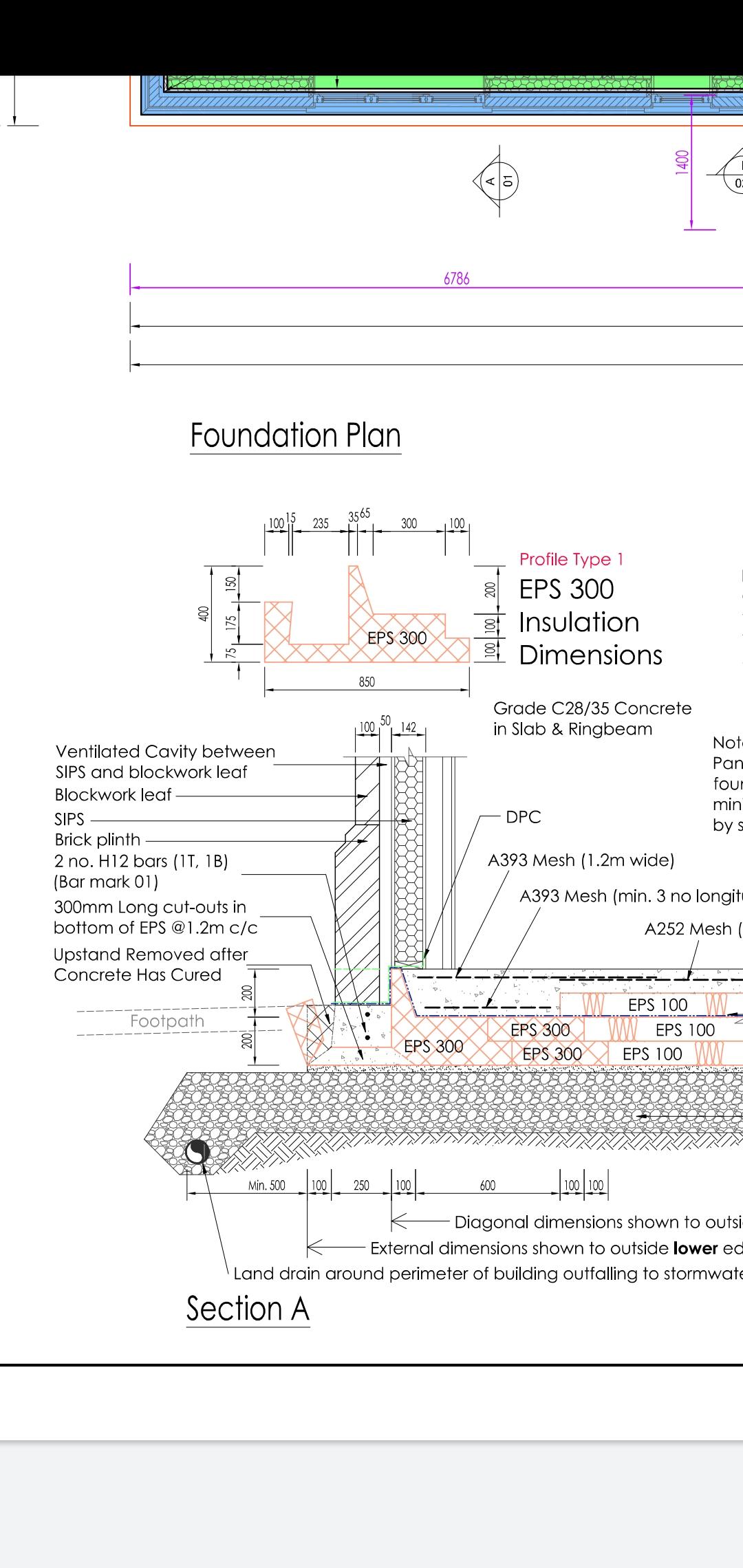
@SuperJohnG I went with blockwork as I wanted a more substantial/solid outer skin. It's a bit of a wind trap where I am so it's just a psychological comfort thing! The blockwork will be rendered so could have been done with render carrier board.1 point
-
Thanks, I think you are right. When I asked to virginmedia online support, I was told "DOCSIS3 cable" but the sales person was not so technical anyway. I've found this guide: https://www.virginmedia.com/content/dam/virginmedia/dotcom/images/shop/downloads/New-Build-Handbook-v1-63.pdf I haven't read through yet but it seems just the RG6 cable is fine. Maybe need to check if there are high quality wider band width RG6 cables.1 point
-
The motor in the fan is an inductive load and liable to damage a dimmer that is only designed for resistive or LED loads. In more practical terms, matching dimmers and LEDs is enough of a pain without making life harder adding more variables to the mix.1 point
-
Ok she has hard slap!1 point
-
So the architect cocked up. The steel beam that is the cause of the issues can't be shown on the drawing or is shown in the wrong place. This is way beyond a few mm drawing tolerance. I would be saying "you designed it to fit that window, you make whatever aerations are required to fit that window, at your expense. As it is, you have a house built that does not match the drawings by a long way. Are you happy with that?1 point
-
Hello, I'm mechanical engineer working in commercial building planning and construction. Besides that I'm closely cooperating with the welding industry. I like designing and manufacturing what ever I can in my life but the fault finding and repair process is my first love. See you on the garage1 point
-
Stacks don't have to be 110mm.... The approved document has a table that specifies the Stack Diameter required for different Flow rates. The minimum size in the table is 50mm as I recall. The top ventilated part has even less flow (none!) so presumably can be 50mm.1 point
-
Sounds like it's doable. We have a public footpath near and across our land and someone pointed out you aren't allowed to drive vehicles over a public footpath unless you have a right of way. It didn't cause us too many issues in the end, although footpath officer said he wouldn't divert it to a new route until the grass seed we had laid had grown. So we turfed it and told him it grew overnight.1 point
-
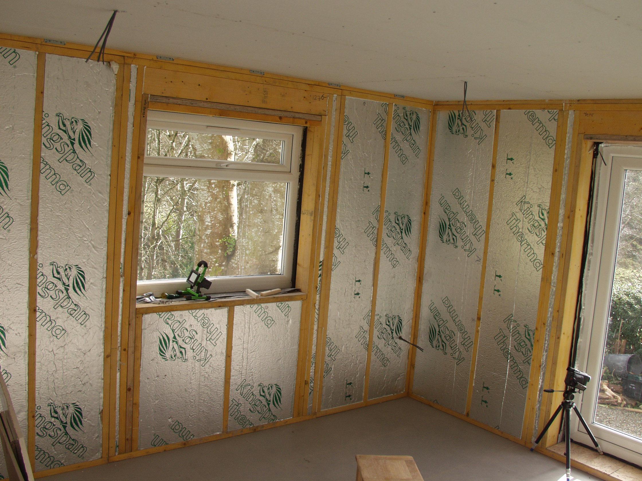
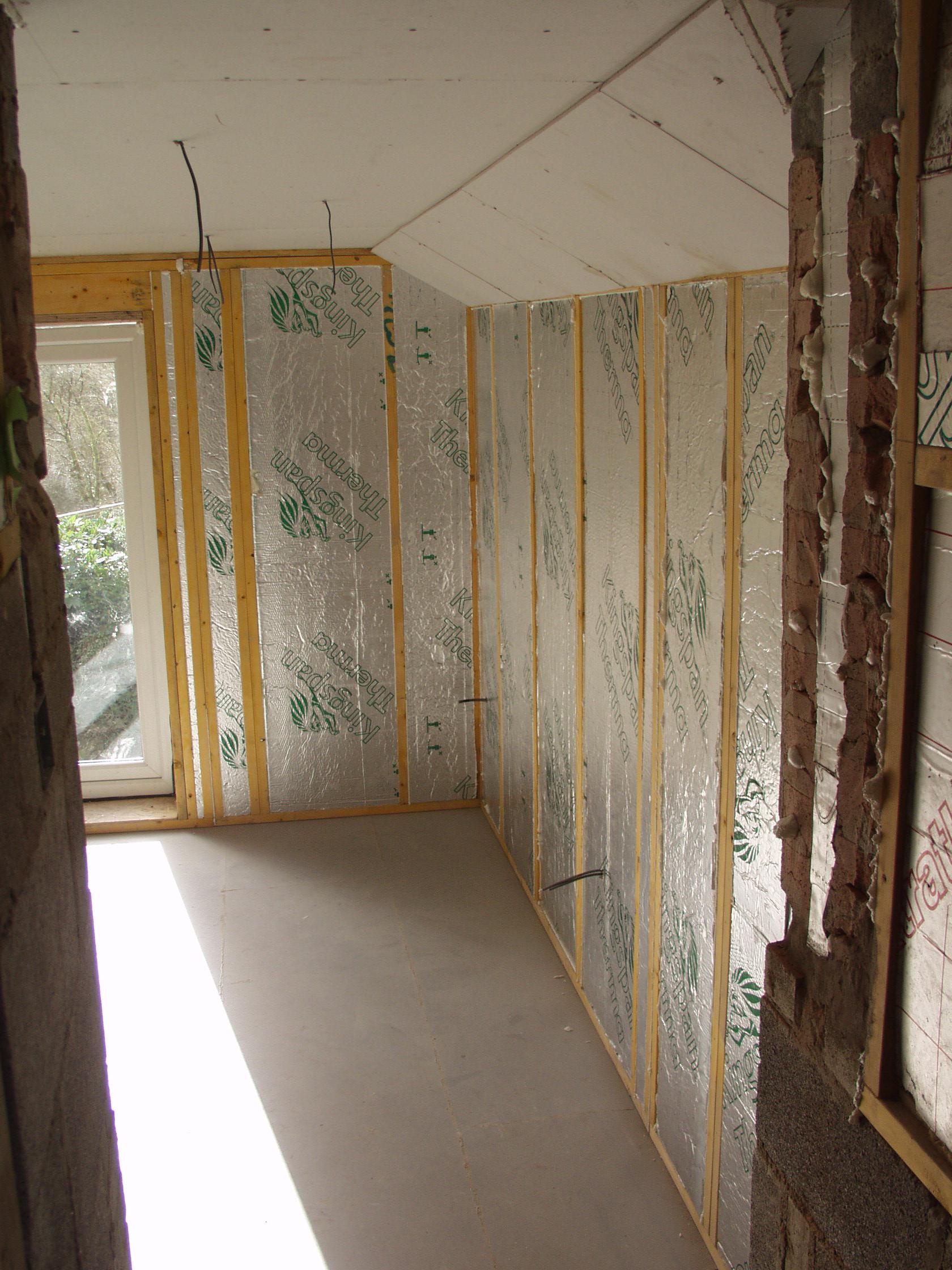
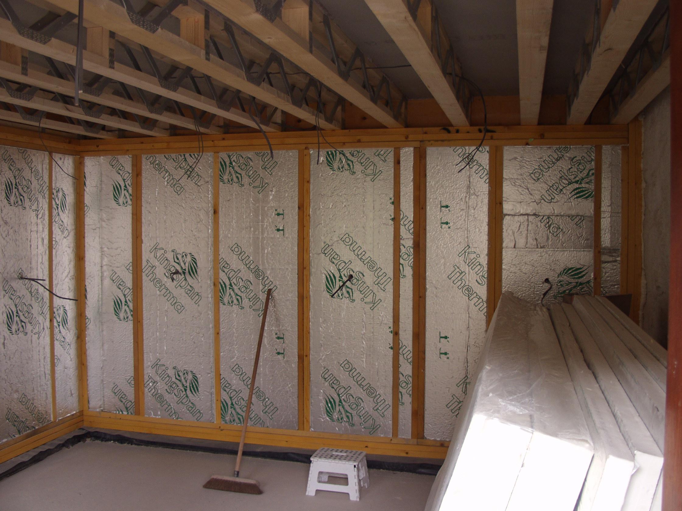
Get a big roll of plastic. Double sided tape it to cover the whole walls with as few joints and penetrations as possible. Anywhere it has to join, overlap by 15cm and use wide foil tape (also screwfix/Toolstation) along the joints. Overlap it with a horizontal plastic sheet covering the bottom of the ceiling joists. Take it into the window bays etc as well and seal it up to the frame with tape/silicon. Ideally join it to the VCL/DPM at the floor, or seal it round the bottom edges. You're aiming essentially to make a complete plastic bag inside the room. The double sided tape can be a generic one from Screwfix etc, just needs to hold the plastic in place while you put the plasterboard up: ultimately the plasterboard will hold it in position and clamp it onto the tape/silicon round the edges to keep the seal tight over time. You can also use some staples to hold it initially in places it wants to pull off the tape, then just put a square of foil tape over the staple. The cold side is the side nearest the outside. Water vapour will travel there from the room (e.g. through little gaps between cut bits of timber, through gaps that form as the timber shrinks, through tiny natural cracks that will open up in the grain of the timber itself, etc). Then it could condense into liquid water and start to cause problems. Same basic thing as when you wake up in a tent on a cold day and the inside surfaces are soaked with the water you breathed out in the night. The "thick shiny vcl outside of the timber frame" should be (and likely is) a breather membrane rather than a VCL. In theory that will allow vapour out of the wall and into the cavity before it condenses. In practice there can be a mismatch between the rate vapour gets in from the room and the rate it gets out through the breather/cavity : the more you can keep the moisture out on the room side the better. The external breather and internal VCL work as a "belt and braces" pair to make sure the wall stays dry.1 point
-
An interesting video of the retrofit of a compact MVHR in a flat:1 point
-
You have tapered insulation so potentially need a range of fixing lengths....used in the correct positions. They will need to be carefully planned. Make sure you spec the requirement for all fixings to penetrate at least Xmm shy of underside of ply deck.....it could change things for the roofing co’s approach to and costing of the job. Actually, aren’t you having a green roof?...in which case I’d be less concerned about wanting mechanical fixings given how weighted down it will be.1 point
-
We’re pleased with the way the bathroom turned... still finalizing the decorations (mirrors, etc).. but it’s largely done now,
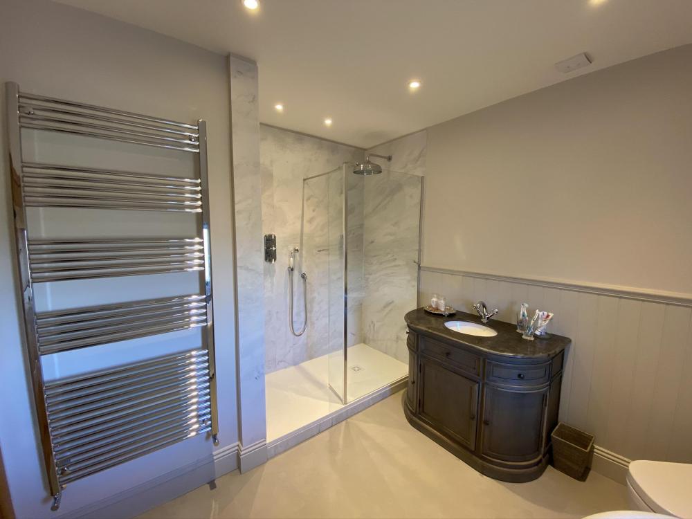
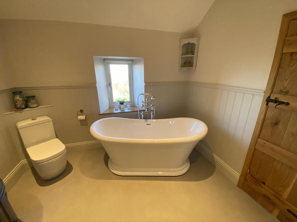
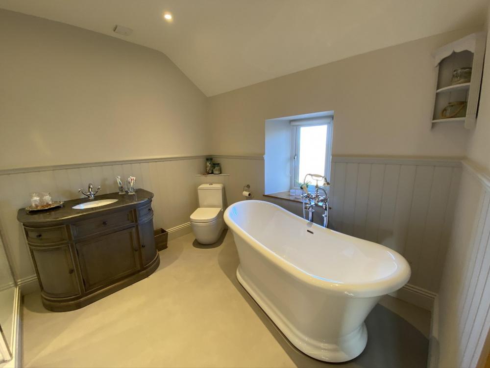 1 point
 -
+1, deffo mechanical fix1 point
-
@SuperJohnG I have SIP with a blockwork outer skin on an insulated raft foundation. The way it worked for me is I first of all had a soil survey done to get a ground bearing capacity. Architectural Technician did my house design which I gave to SIP company and asked them for the point and line loads. They used their SE to get this for me (incl in cost of the SIP supply/install package). I then contacted Tanners and provided him with the soil survey report and the line/point loads of the SIP and the house design. They then produced a foundation plan which included a slab for the TF and a separate ring beam to carry the blockwork skin. Gave this design to Kore and i am now pulling my hair out trying to build it in the worst February on record?♂️?
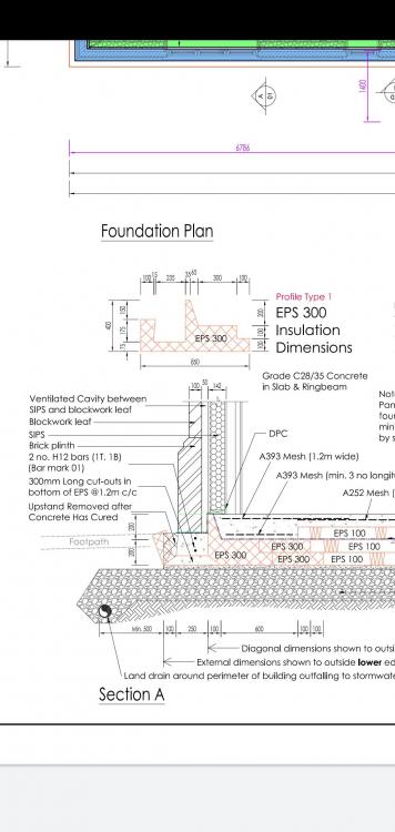 1 point
 -
i personally would not trust glued down insulation. i got to a site one morning to see loads of it all over the place. The cloth surface had been let behind...Mech fix for me, all day long.1 point
-
Yes i do roll it. Don't use too much glue, and wipe up any that squezes through with a damp cloth. (Have a cloth in a bucket of water.) I usually lay 3 rows at a time. I will cut, and dry lay the three rows, mark the edge with a pencil, lift the boards back towards you as a stack. Lay down the glue, using the pencil line as a guide. Picking the boards from the top of the stack, lay, roll, and wipe. The last one i did was 60sq meters including 4 door ways, and it took me 2.5 days. Have fun. Re the glue. Don't use too much. The first time i layed it, i did, and it slides around like a pig, and takes forever to dry.1 point
-
Send the same pic to. Brick hunter .com If he can’t get it it doesn’t exist1 point
-
1 point
-
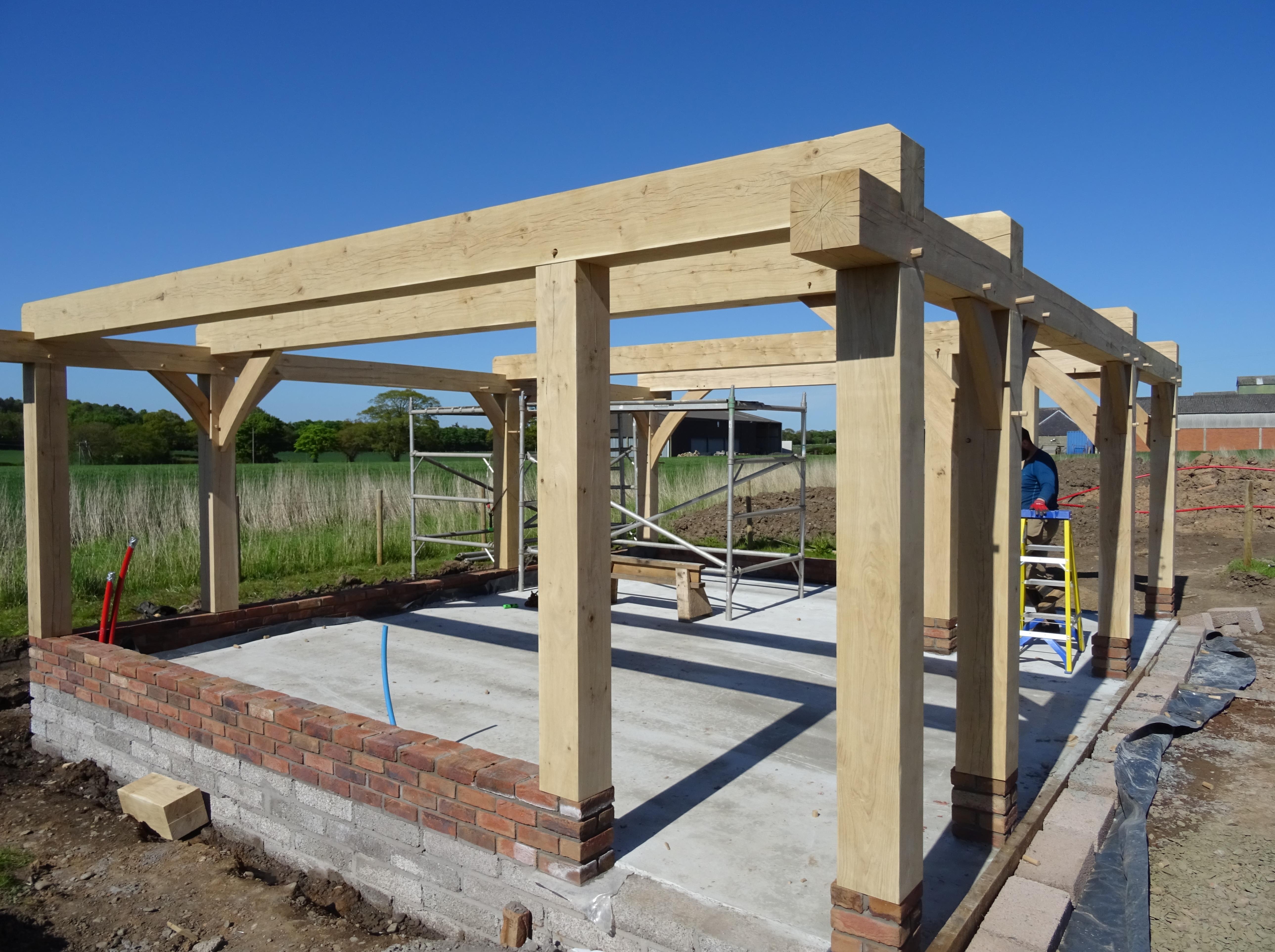
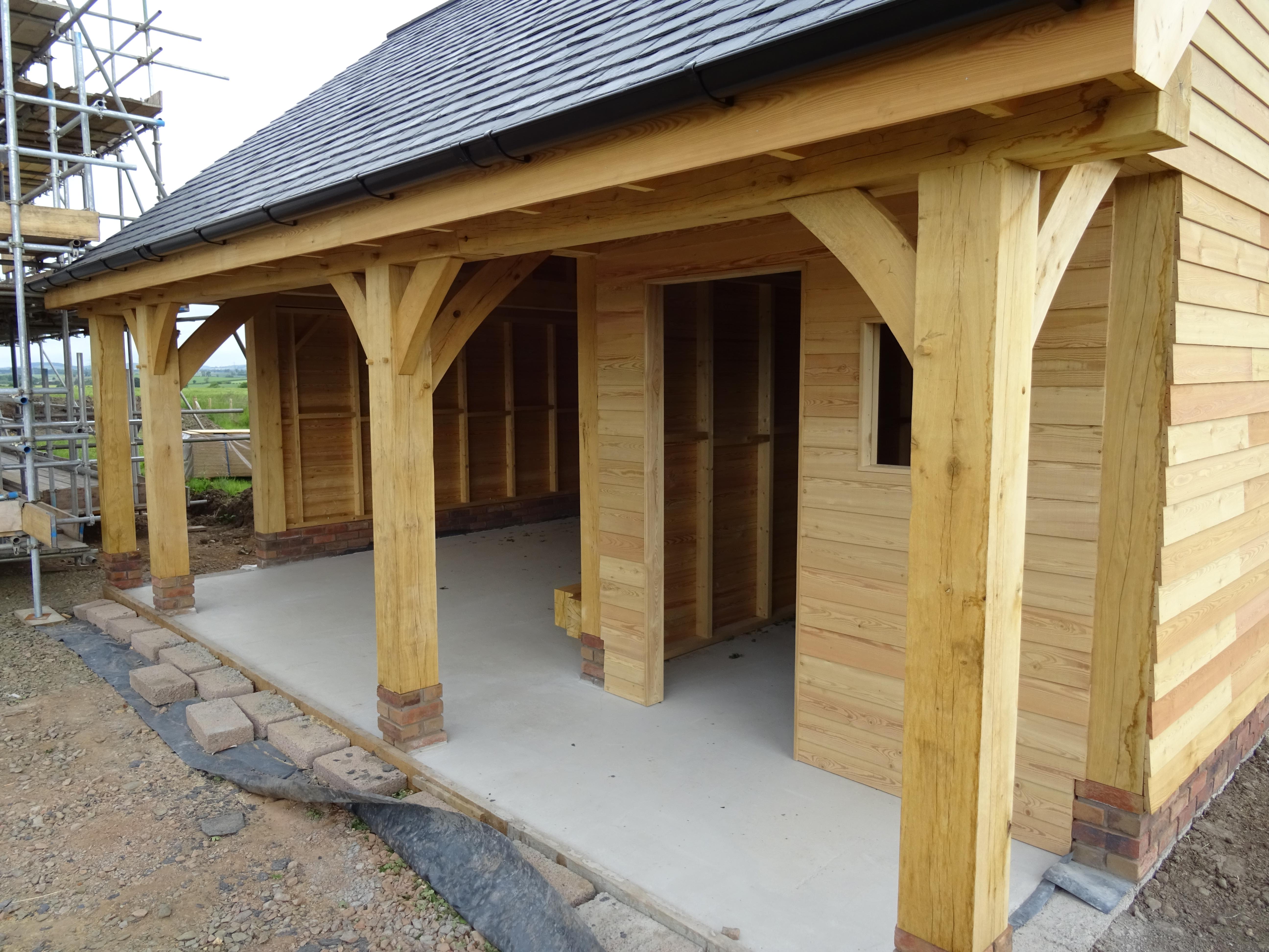
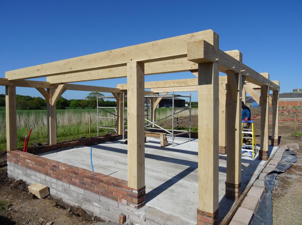
We have a timber framed carport and combined shed that is built upon a concrete slab with a twin dwarf wall. The bricks are a range of heritage bricks from a builders merchant so nothing specific as to needing to be an engineering brick etc. We dont have a damp proof course between the supporting bricks and the oak posts as they are protected by the external larch cladding. I'm sure a competent bricklayer / builder / DIYer could lay the bricks. See images below. Although everyone has their own reasons for doing something or not as the case may be for @Carrerahill, I'm very pleased with our timber frame construction. It is oak framed with larch panels, so I don't intend it to be going anywhere anytime soon! That said, I won't be doing any welding in it either. ?
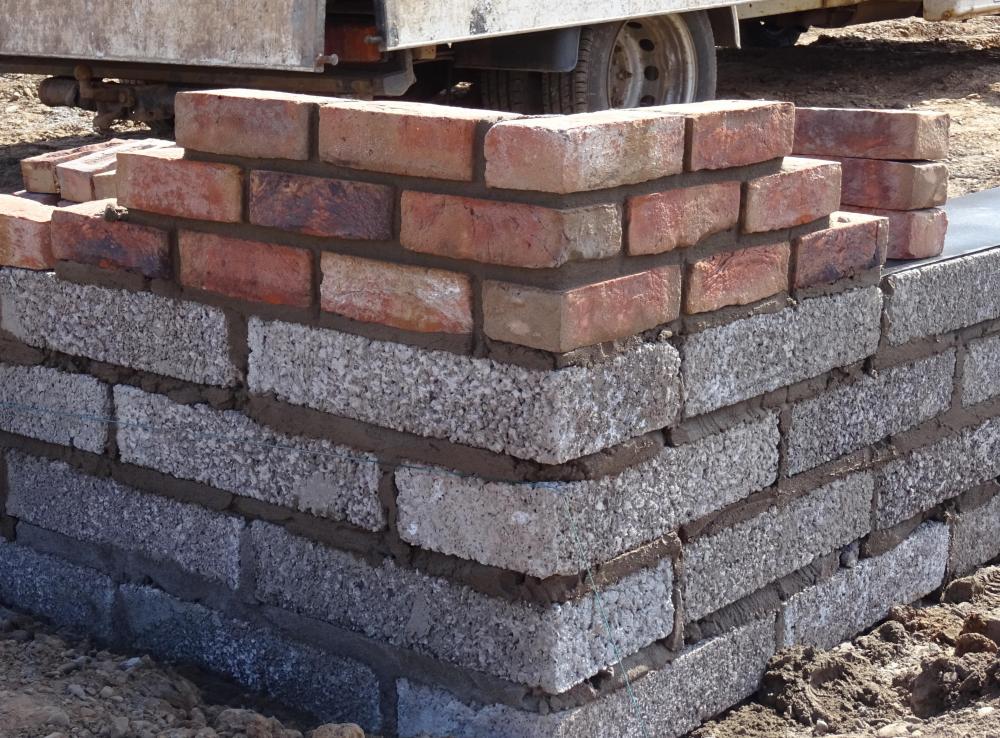
 1 point
 -
Thought I'd add this to the blog but would be very grateful for some advice. Some construction background: MBC timber frame, flat roof, pumped insulation in roof void. Make up of roof is Sarnafil (hot welded) laid on a felt base, on top of 22mm OSB roof (with a slope), on top of 22mm OSB roof deck (flat - slope provided by battens to create the fall), then 400mm pumped insulation between the roof joists, air tight membrane, battens, 12mm plasterboard and skim. Roof lights on the flat roof (including a lovely round one, subject of another blog post). Yesterday we had some drips coming through the finished ceiling, about 700mm from the edge of our circular rooflight. We cut away some plasterboard to see what is going on. Plasterboard soaking wet, batten soaking wet and looks like the insulation is soaking wet. There is some water damage closer to the rooflight too, visible in the photo, but we started our cut at the plasterboard edge which is where the water started seeping through - the low point I guess. Have contacted roofing supplier and rooflight supplier (both of whom fitted their product). What shall I do next? I can't help feeling that without detecting the source of the leak neither supplier is going to help us. Any thoughts? Cut away our ceiling until we find the edge of the problem? (as we get nearer to the rooflight bit of course we are 7m off the floor ☹️)0 points
-
Wow - your photo is almost identical to the mess we exposed today, condensation on the lower side of the OSB with soaked insulation. We have exposed even more of the area now. The middle section is the problem area. It has been a long day and we have just finished clearing up the mess (that pumped in insulation takes up alot more volume when it is pulled out!). We have looked back at all the build photos and the construction drawings for the upstands for the roof light. Its a bit of a puzzle but we are hypothesising that the water is leaking in through a mastic seal onto the frame of the rooflight (which sits under the glass). It is then leaking through a screw hole into the upstand (timber) (the frame was fixed into the upstand with vertical screws), travelling down to the bottom of the upstand where it joins the roof joists and then spreading both above and below the vapour membrane (the drips are coming from below the membrane, but the insulation within the membrane is soaked also. Of course there could be a leak in the roof material somewhere but that theory is not so obvious given where the water is being found and the lower roof deck being dry. Tomorrow and Saturday are supposed to be dry (no rain hopefully) so we plan to get some water up there and selectively test the various areas. I have messaged both companies inviting them to be present. I'll video the tests so we have some evidence because fixing this is going to cost someone some money. Thanks for all the advice, and supportive messages today. It is good to know you are all there.....0 points
-
Anjelica Huston she's not ?0 points
-
It seems the foundations have been undermined, along with the loss of about 30ft of their garden. The local authority refused the planning application on the ground of flood risk. The planning inspectorate rejected the appeal on the grounds of flood risk and the Welsh Assembly chose to over-rule both.0 points
-
Can I ask why it took you so long to complete?0 points
-
Nah...you’ve just copied some pictures from a magazine or a holiday website?0 points
-
The EU have 100 degrees in a right angle so you get these odd half degree amounts when you do the conversion to "imperial degrees".0 points


.thumb.jpg.bac90f3bbf6868cf2118d010d936c99d.jpg)