Leaderboard
Popular Content
Showing content with the highest reputation on 11/23/23 in all areas
-
Agreed @saveasteading, but I'm unsure if I'll follow this through as my main concern is the quality of what I have and the general consensus is that its fine. To go for cost rebate, I'd have to be 100% sure of depths in middle of floor, which presumably would call for a couple of drill holes, which is a taking from quality and would rankle the builder if I'm wrong - on balance, I think it's best to move on.2 points
-
I followed your @TerryE story a number of years ago and designed my system based on your posts. Thanks for all your detailed posts all those years ago. My system: Installed and running 4 years instead of 6 yours like yours Heated by the same 3kw wills heater during the night 100 sqm of polished concrete, 100mm deep and reinforced with fibres not a steel mesh. Self installed Wunda 16mm PERT-AL-PERT PIPE, manifold and pumpset - 5 heating loops with similar double back loop design. The pump is on a low nice quiet setting. I’ve no idea how to calculate how much water it pumps or the flow like you did nor do I feel I need to. It's working so I’ll leave it. I’ve a temp difference of circa 5 degrees after the system is up and running. It’s the basic temperature dials on the manifold so this isn’t digital or recorded like yours. Portable oil heater for the misses for when she thinks she’s cold. We’ve our temp between 20-21 degrees so lower than yours It was a major refurb, not a new build but we did a PHPP for the house which I can compare to. Main differences: I don’t have all the fancy temperature probes or data logging you have. We have temperature sensors but they aren’t recorded. I could fix this by purchasing a few but don’t really feel the need. I have an electrical meter on the wills so know exactly the energy going into the slab. I don’t run the pump after the wills is off to spread the heat like you nor do I do it for a few minutes on the hour. I did play around with this for a while at the start but it doesn’t make a massive difference. This slab is all one large open plan kitchen / dining / living / entrance hall area. You do notice the floor warmer in the hallway nearer the manifold but this is fine as the heat rises in this double height area to the upper unheated rooms. Things I’d change: I don’t have the fancy controls you have nor do I have the coding skills to develop it. It’s therefore a much cruder timed system. Note I’m based in Ireland, not the UK. For the first two years it was definitely cheaper to use a cheap wills than invest in an ASHP but the massive increase of the electrical unit rate has changed this. I've had the ducts fitted for years from outside to the wills heater so it’s an easy swap we’ll have to make soon. All loops are circa 90-100 meters long so I’d like to connect the ASHP directly to the slab avoiding a buffer too. Question: If I were to data log temperatures does anyone have any advice on what products to use that don’t require coding, are relatively cheap and what number would you advise getting and what to record? Do I go all out and record the flow and return temperatures for example? My biggest achievement: For the winter period 2021-2022 when everything was turned off in Spring the total units used was 3,347.1 when PHPP has a number of 3,349.0. Other years were higher or lower but that year was bang on!2 points
-
We went with a Kore foundation designed by Tanner. This was for an ICF build. Raft was 150mm thick, with 250mm ring beam. Total depth of footings was 800mm. The breakdown was as follows: 300mm - MOT Type 3 50mm - Sand blinding 300mm - EPS 150mm - concrete raft The ground make-up was sandy gravel. I’m not sure if Kore still ship to the UK, I asked them directly to recommend some UK based installers. Back then Kore were being used by MBC Timber Frame for their foundations. I was very pleased by the shallowness required for the footings. I feel like any experienced ground workers could put in an insulated raft. The actual execution is quite straightforward.1 point
-
No 1, if you are expecting to lay in the cables and then get an electrician to sign it off then find that electrician first and discuss the details with him. Electricians can sign off work partly done by others, but are not obliged to, and many will not entertain that. What cable are you proposing? 2.5mm conduit singles will fit in 20mm conduit okay. If you really want to, 2 lengths of 2.5mm twin and earth will JUST fit if you are careful and keep them flat, no twists. NO chance of a third (lighting) cable in the same conduit if you choose that. Personally I would just run one run of conduit horizontally from socket to socket no tees. And a separate conduit up to the lights. Read up and understand safe zones or agree routing with your chosen electrician.1 point
-
Pretty straightforward A quote is a quote Had they got it finished quicker than expected Do you think the would have cut you a discount? I agree will the above But I would try a more straightforward approach Tell him to bugger off1 point
-
Pre drill a clearance hole in the first piece(that you are fixing through) then twin fast screws, beware to screw slowly if using a power tool as they pull in fast and use the clutch on your driver…Furniture Chipboard / Twinfast Screws, also known as particleboard screws. These self-tapping screws have a coarse thread with twice the thread pitch of standard wood screws, making it easy to drive them into a variety of materials such as chipboard or various densities of fibreboard.1 point
-
It will. The sad thing is it an easy, but messy, fix. I suspect that they did not put enough resin into the first layer of mat. I hope they put a second one on, but may have not. Water will get in, will be absorbed by the unsaturated mat, freezing will happen, then it is just a matter of time before it fails.1 point
-
On the white cupboard fit a bottom rail to match the top rail that exists, these then have a 15-18mm gap to the edge of the side panels, glue 15-18mm (whichever it is) timber to the back panel to match the top and bottom ones and you then have up to 36mm to screw into the back panel from the inside of the cupboard through those supports. (I can do you a cad, crayon assisted, drawing if you want 😇)1 point
-
1 point
-
Screws through the back panels for me, then you've an easy removal if ever needed. glue some filler pieces in place to stop the back panel bowing when the screws are sent home, just measure the panel (18mm)+ gap and add 15mm (assuming the back panel is 18mm) and select the correct screw length.1 point
-
So you just want a relay, with a 230V coil, that'll switch 230V at some amps?1 point
-
I've a few relays and bases kicking around here. Resistors too.1 point
-
That’s sounds a nice detail. Can’t quite imagine what it will look like but birch ply is nice. Look forward to seeing it.1 point
-
yep a couple of hundred K would be worth a try, it's what we would fit across a starting capacitor to ensure it discharges. Or an old-fashioned pygmy 15W filament bulb?1 point
-
Great, when you cut into the tile, cross cross with the angle grinder to break it up and use (very carefully ) a centre punch to remove very small amounts of tile at a time. Never used one but a dremel or similar may help.1 point
-
As an estimator I always do / did this if it was my own take- off. For part of a big job it is near enough quits with brick or plaster area saving being near enough = to the fiddly work. But as a bricky or plasterer it would more significant. Thus if you deduct some fiddly work, there is a genuine saving in time and cost. BUT change is never good. At the very least, they had to remember not to do that bit. Contractually, they are entitled to the profit they would have made on thd work deducted, even if there are extras. Some compromise is required.1 point
-
Yes. My "neater" scheme relied on one CAT6A per room rather than per device, so was about 15 cables not 32 for me. Also I needed all cores connected anyway as the brown and blue pairs were on retractive switches into DIs Using interconnected and ignoring unused pairs is fine, especially if you leave a bit more space around the terminals to manage them all. Not each interconnected block actually had 32 spring terms! As they're paired and there's 8 pairs on top pitch and 8 more on the bottom pitch. Personally I'd use the 16 topside terms max for the outgoing cables, but that's still just 8 blocks needed for all your power and tree on these cables. Note the last photo I shared was actually hybrid: interconnected blocks for orange and green, and separated blocks for brown and blue. Slightly tricky, but the sweet spot for density ime 2 layer are 2 layer plus earth. So each T+E needs a 2 layer, each 3+E cable needs a 3 layer block (as a good approximation). For 5 core I normally use 2x 2 layer. Yes. Assuming you have switched live then use busbars to common across all the neutrals. LED strips (if on T+E cable) tend to have common +24V and dimming on the negative leg (so called common cathode) so these you busbar the +24V positive side instead.1 point
-
1 point
-
If you are filling the cavity with concrete, you obviously don't need a cavity, so why not build as a solid structure. Block on its side 215mm, plus block 100mm wide installed normally, gives you 315mm. Your build is 315mm wide also, plus all the faff of concrete fill.1 point
-
But, can packing the gap do any harm? Common sense says not (IMO). despite the technical knowledge supplied by @Gus Potter can squeezing two separate metal panels together with no support between be correct? What torque was used to tighten the bolts?. I am no SE, but that just looks wrong mechanically.1 point
-
I like @torre's idea also, maybe with a bolted fixing - but then you are probably going to need some custom metal bits made. Great if you can get those done easily. I just re-read the manufacturer's suggested fixing method using screws only. I somehow assumed they would use an accurate pin to stop sideways movement. I think a metal dowel pin, say 10mm, and a corresponding very accurate hole in the tile (and the bottom plate) would do it. The hole in the tile will need a diamond drill so it'll be nice and accurate. Screws and plugs are always a bit wobbly - fine for small loads. The key force you're trying to counteract, of course, is the sideways shear caused by the weight of the door acting 1/2 a door's width from the pivot point. This kind of thing:1 point
-
No such thing, stupid is not asking🤷♂️, the advantage IMO with batts are that they are a bit squidgy so can be stuffed into gaps, boards are solid and require taping or foaming to make them effective. Also I don’t like the idea of a “plastic” insulation (Grenfell!!,)There is an argument against full fill without an air gap but mine had a bba certificate fir full fill and even when a wall got soaking wet through none if it migrated into the insulation.1 point
-
The principle is quite simple. To get a fixed amount of air though a restriction, in a fixed time, you have to speed the air up. This reduces the pressure at the restriction. What you can do is add extra air at that point. That air gets sucked in and then dragged out. So more air movement for the same size fan/pump. It is what Dyson does quiet well, but he relies on the general public not realising that it was all formulised in 1738, by Daniel Bernoulli.1 point
-
Well at the stage you figure out the shortcomings in the best tools, that makes you an expert1 point
-
It's on its way back, should be there today, no refund yet, assume they want to see it, as it was sat outside for 6 weeks while they tried to help I've gone for the Samsung 5KW. managed to get the control kit new off eBay for half price so helped ease the extra cost, plus they do a coastal version.1 point
-
1 point
-
The first link would probably do, but we would need 2 of them. A bit pricey for something so basic looking. The second link looks a lot nicer but even more expensive. But it does give me ideas how to just go and buy some wood and make my own. When building our first house we considered Caithness stone for the hearth. Got a similar reaction to you and a quite ridiculous price to cut a piece to size. In that house we used ceramic tiles on the concrete hearth. This stone for the shelves (and previously for the kitchen worktops and stove hearth) came from Stone Source in Inverness.1 point
-
I guess I'm still old-school solder ring tech - what do you use that press for? Can it do air hoses?1 point
-
1 point
-
Sucking is likely better than blowing for this application. Blowing is directional, and has significant turbulence - good for heat transfer admittedly, but it will vary hugely over the heat exchanger - not what you want. Sucking gives a more even laminar flow over the whole heat exchanger. No puns in there 🙄1 point
-
1 point
-
Self building means you need to build a relasionship with the folk you are working with on site. I know you are trying to get a price for everything but that is not the best way. Six cube of concrete equates to a 15 tonne load of concrete ballast and a few bags of cement. Talk to your guys on site as this is the kind of job that can be done when the labourers have not much else to do. Bung a bit of cash their way and it will work out fine. If you know what you are doing then hand mixing six cube of leanmix over a couple of day is not that hard.. I have done it many times over the years. I think a lot of folk have gone far too soft.. it is less onerous than picking Asparagus in Linconshire and you don't smell so bad in the toilet after.1 point
-
@Mattg4321 having lived in an almost identical space for 8 yrs, from our experience: we initially had a secondary sofa area in the big room (in the dark corner), plus a TV. Plus dining table, island etc. They (sofa/tv) were rarely used so we removed the sofa so there was a telly on the wall which was more used for casual watching while cooking etc. we kept our lounge separate, it looks like yours is around 4x4m too. Difficulty with leaving it entirely open plan is a lack of cosiness and if you use a set of internal dividing doors, etc is you have limited walls for seating options as it looks like you’ve got a fire on the right hand side. If you’re able to shift the living room door into the corner too even better. I would recommend you consider keep the livingroom entirely separate from the extension especially if the kitchen diner is likely to be a busy room. It’s a retreat to go to unless you live in a magazine and your kitchen is permanently immaculate or quiet. Your large open plan space would allow for, right to left, an amazing spacious kitchen with a feature massive island, large dining table and perhaps a reading chair or two in the dark corner or in front of the large glazing. your square meterage is great but the square shape and locations of doors and glazing makes it tricky to get effectively three functional rooms into there and it could look and feel a little cramped. If you had a rectangular space 10x 5 it would be easy to divide into the three zones, but you don’t. I sense that’s your dilemma. A lot will depend on your actual need for a second telly and sofa area. If those are not essential consider binning them. Good luck with whatever you decide.1 point
-
Self building creates resilience, and self builders have a lot more than most. We're used to getting on with it after hitting yet another brick wall.1 point
-
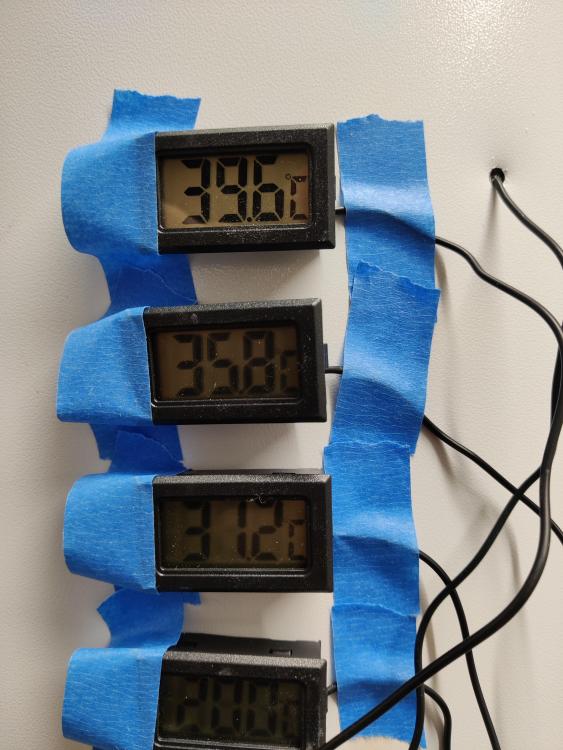
Slight update. Cancelled the cylinder charge scheduled for this afternoon, so last charge finished at 7am this morning. Set point was 48, it took 45 mins to charge the 210L slimline cylinder from a 6kW ASHP. Wife showered this morning and general house usage, I also showered, shower temp ok, but not as hot as it was yesterday. So have upped the temperature to 50. Added some additional temperature gauges on the cylinder this evening. Prior the shower the normal temperature probe was reading 21 degs, but it's close to the bottom of the cylinder. So pretty meaningless to the content temperature and how much hot water is remaining. 4 cheap temperature probes, a 6mm to drill through the outer casing and I had a very basic level gauge. Interestingly the gauges at 21 degs read within 0.1 of each other. Not bad for £24 for 8 off including delivery. Tappings are 250, 500, 750 and 1000mm from top of the cylinder. So down to 50% of the cylinder height. Will check the temperature reading in the morning to see how accurate they are. To me it looks like the top 500mm of the cylinder is still quite usable. Next job is to tidy the gauges up and look a little prettier.1 point
-
You can make yourself a little test board from some ply etc with a little lip round it. Maybe try it out with the depth you're planning and see how you feel once it's set?1 point
-
My idea worked out so well! 3 perfect cuts and two perfectly placed holes. Small achievement for pros but a massive one for me....chuffed to bits!1 point
-
It can look quite patchy in colour and texture. I'd be surprised if it looks good enough for a finish. Also it's quite brittle so might crack or lose adhedion if something is dropped on it. Latex based stuff is more flexible. There used to be 2 part stuff that was great but I havent found any recently.1 point
-
You could look at Glulam - Buckland Timber, who I can recommend, do glulam in Oak as well as a number of other timber species. This could be advantageous for a number of reasons. https://www.bucklandtimber.co.uk/1 point
-
1 point
-
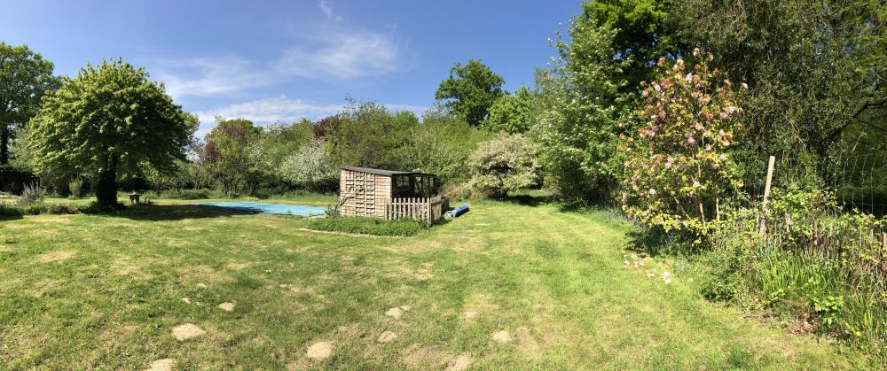
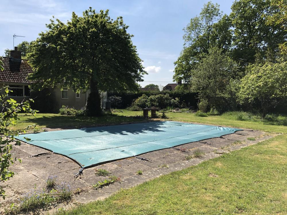
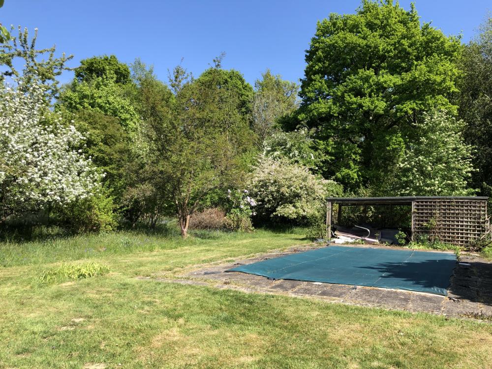
@Russell griffithsI realise that my response might be taken as being a bit rude and curt! I apologise if it came across that way. I've just been made to feel right at home on the forum and spoke as if we were just chatting down the pub but I'm not sure I'm there yet as a newbie and probably have to earn that right. anyway, I felt bad so I just went outside and snapped a few photos for you. ? here's a panoramic view looking north. the swimming pool is where the main new building will be. we have ancient woodland to the north and east (just visible to the right of this photo). and here's a photo to the East of those Ancient woodland that can be seen beyond the pool and pool house. (I think the picture tells a story that the pool and pool house aren't in a usable state!) the north end of the existing garden is currently an orchard. it's a shame that the majority of the trees will be removed for the new driveway, garage and house but some will remain and new trees will be planted to the south of where the existing building already is. here's a photo to the south west at part of the existing bungalow. and finally a snap of my boy and the bluebells growing in the garden. we love it here. ?1 point
-
I never did, thought I perhaps could, couldn't and now don't care.0 points
-
No, 100 ohm connected to 240V is (V2/R) is 576 watts, apart from wasting a great deal of power, your 1/4W resistor would last milliseconds and end in a big flash. 100K Ohm would be about 1/4W but without trying it you would not know if it would quench enough.0 points
-
That was never discussed as an option, they instantly said they would supply a replacement. There has been no mention of returning the wrong one. If that turns out to be the case, then when we make our posh shed, it just might have a bar made with the spare shelf0 points
-
0 points
-
0 points
-
0 points


