Leaderboard


Popular Content
Showing content with the highest reputation on 06/17/23 in all areas
-
Day 31 of the build. (this is taken from the day we started shuttering the foundations) The weather up North has been spectacular for about 3 weeks, so we (Mandy and I) pushed to prepare and pour the slab before the weather changed, as I'm sure we will get a few weeks of low pressure, wet changeable weather after this spell. Following on from the foundation ICF walls, I'd already loaded around 20ton of 40mm to dust in a pile the slab area. Sat on the sand blinded radon barrier. Job one was to sort the drainage. I'd posted previously about my plan, and some constructive comments suggested changing my planned route, but with the extra length of run to the drain invert level I would have had to increase the floor height even more. So stuck with my original sketch. We ran string lines to mark the main areas, namely WC, SVP in the plant room, shower, WC and Bath, a need ran the drainage to the locations, as the utility backs onto the plant room I didn't add a drain in here as I'll run through the stud and use the SVP. Once the drainage was in place and is tested. We spread out the hardcore and compacted it. I used 10mm crush and run to bed the drainage and cover the pipes, I also ran ducting at this level, bringing in water, power, treatment plant feed plus some future ducts. To get the hardcore level / flat I used 3m lengths of galvanised conduit set on mortar pads all level to each other and used a 4M ally beam to screed the slab. I compacted the first layer then used another screed pass to fill in any deviations and used this as the level for insulation. I used a combination of 200 mm EPS 70 (50mm sheets and 100mm sheets all layed to stagger the joints, and used foam to seal to the ICF. The top layer was 100mm EPS150 this gives a firm hold for the UFH staples, and a firmer feel to the insulation layer. We plan to use a large shower tray and have this level with the floor, so I made this area sunken with two layers of EPS150 and a layer of 50mm PIR. As we were installing the insulation I installed 2 * 100mm ducts for the ASHP in the second layer of insulation these were only 800mm long, and a duct for cables. I also added flex ducts in the insulation for Hot & Cold services to the kitchen, utility, WC,Shower,bath, all these were cut using a hot knife. Lastly I cut some pipe for floor sensors in the kitchen, lounge, bedrooms and bathroom. The underfloor heating consists of three loops around 95M length, planned using Loop cad. The manifold was plumbed , filled and a pressure gauge to ensure no leaks. We have good water pressure so could pressurise to 6 Bar. ( With the heat ☀️ this rose to 9 bar one day). The above picture also shows K Steel screed rails. I used these to break the slab into smaller bays, and mainly will be under stud walls. The slab will for the foreseeable future be our finished floor, so I wanted to introduce expansion joints and force any cracking to these locations🤞. I also used Tibmix metallic dry shake topper on the concrete, the dry shake should help suppress the fibres and also increase the surface hardness. The pour happend on Friday 16th June, the first 5cube arriving at 8.30. we did the kitchen bay first which needed the 7t 360 to move / place the concrete, then, poured the WC / plant room and utility bay. This was an error, I wanted to pour the lounge next so both bays could be finished at the same time, but under the pressure of the pour took advice to do the awkward section next. This resulted in only a 3rd of the lounge bay having concrete, so this was spread out lower so the next load could fill the bay. By the time the second load arrived, the kitchen and utility bay was ready for power floating. The pan worked well and I had some time to start edging the slab, the rebar didn't allow the power float to get to the edge of the slab. By 13.00 all bays were in and leveled, but not floated, but the sun was very hot, and the kitchen bays was getting hard rapidly, I managed to float this but was struggling to to get a perfect finish. To dry shake makes the surface hard and this was apparent, the lounge and bedroom bays floated better, and to the main the dry shake suppressed a lot of the fibres but there are still some visible. The kitchen bay was rock hard by the time I managed to float again, and although it is fairly flat you can see, but not feel, the path of the power float. I used Setseal 6 as an acrylic sealer, which seals the surface and aids the curing process. By the time we finished the floor was rock hard, I mean hard, the idea being that the slab will slowly cure now but will not be affected by rain etc. Time will tell. Due to the temp, and the float not getting to the edge, I will have to carry out some remedial work on the edges of the slab, as by the time I go to troweling these it was too late. Today the slab looks great, it's flat and level, but the perimeter 2 inch will need some polishing, as will a section in the plant room. I'm confident I can get this fixed. Time will tell. The following picture doesn't do the slab surface any justice. It looks rough, but it's glass smooth. So 10.5 cube of fibre reinforced concrete. Power Floated, and this was non stop until 17.30. My chest and fore arms are wrecked from trying to tame the power float. I'm a little disappointed in the edge finish, but looking at it another way, it's way better than if it would have started raining, or the wind that we have today. I'm sure a few hours with a wet diamond polisher will rectify the edges. Maybe another hand would have been good. 🤔. Onwards to the ICF walls... .3 points
-
2 points
-
Fixing to slabs is not a good idea unless they are fully bonded to a solid concrete base as well (IMO).2 points
-
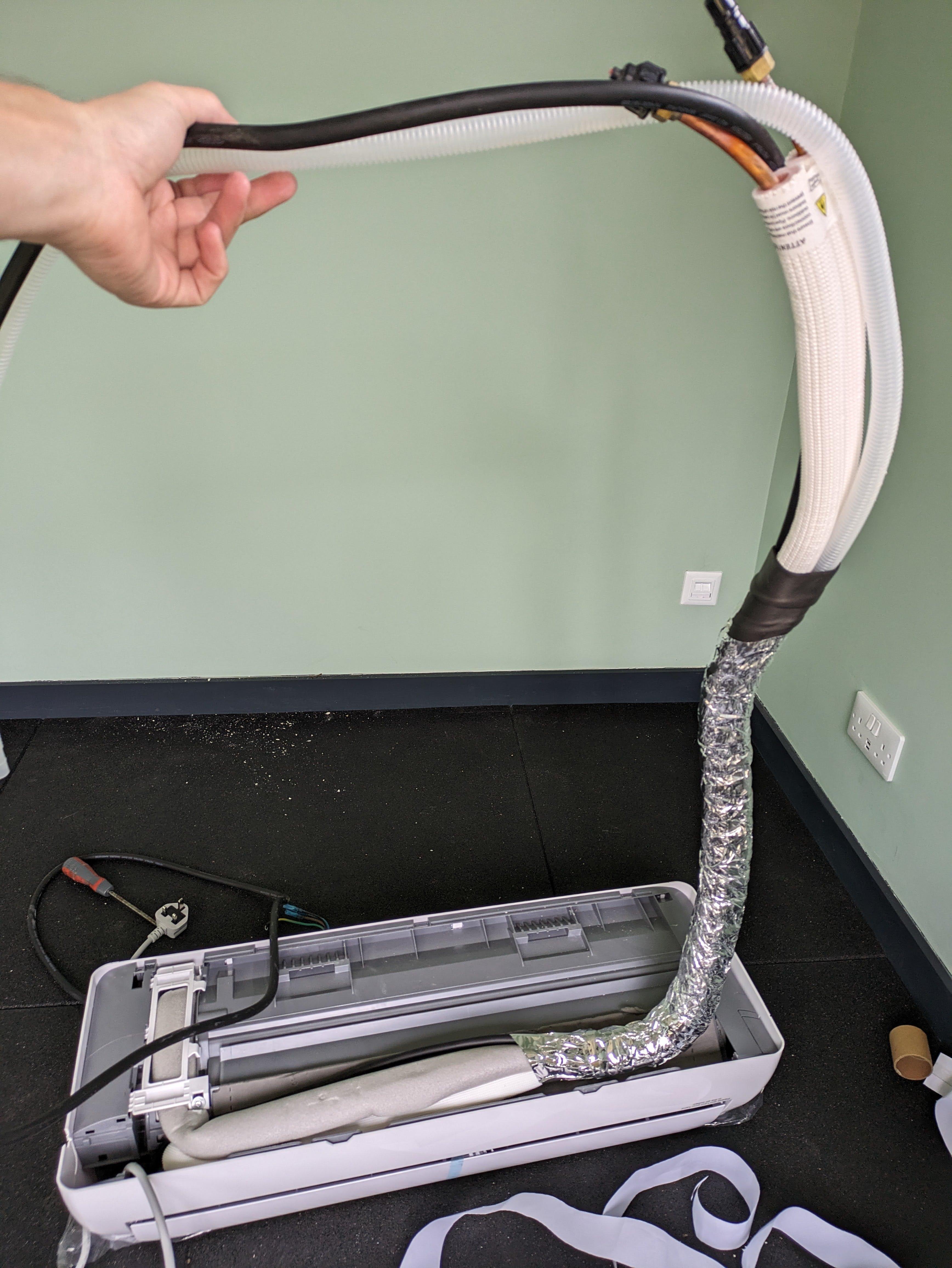
A short blog to show my Mini spilt Air2Air install, in the Windy Roost Static. I looked at installing a wood burning stove, but we have zero trees on site, so when I looked at the costs of twin wall flue, terminals, flashing, creating a heat shield and making the caravan tidy plus the hassle of getting wood / coal, the costs were adding up. A quick question on here - Build hub, some options were suggested and I decided to go with the a cheap Air 2 Air heat pump from Appliances direct. The unit is a Telefunken 12K BTU split unit. cost around £375 but did not included the pipe to connect from indoor to outdoor unit. I got 5M twin insulated copper pipe with the flair nuts from ebay for £56. Our Static has a gas fire - useless, and a chimney breast made from chipboard, the side panel just screws off to access the flue. This was the perfect place for the indoor unit, as it would be a neat install and the rear will allow for the pipes to be hidden, also I could use the hole in the floor to route the pipes/ drain and power for the remote unit. I removed the light fitting, screwed the bracket on the timber, and drilled a 80mm hole, for the pipes / drain and power. Then its a case of posting all the pipes/ drain and power cables through the hole, really straight forward, the indoor unit then just clips into place. The indoor unit comes pre wired with a 13A plug top, and you need to run a 3core and earth cable from the indoor unit to the outdoor unit. this is Live, Neutral and a control / switch cable. Next to the chimney is a double plug socket, so I wasn't messing around running new cables, I just drilled an 8mm hole in the side of the chimney breast and used 2M extension lead to plug the unit in. I used some zip ties to secure the extension lead and plug to the pipes (these were put on after the photo below). and that was the internal work complete. zero mess, and no rework / decoration required. The outdoor unit was going to sit directly outside, behind the chimney breast, the ground outside was not level but it is bedrock, so a made a simple frame and made level concrete pad, and cast some hook bolts into the concrete. For initial research I spoke with a Local (ish) refrigeration engineer, and he said he would connect for £120. but was telling me there is nothing to it, and if I was doing everything else then maybe I do it all??? I found an American You tube guide which was helpful on the pipework side. (linked below) Basically, the unit comes pre charged with gas, so you are not filling with gas etc. the main issue is removing the air from the two pipes you install. This is done with a vacuum pump. (some more expensive units come with pipes and they are pre-vacuumed with quick connectors) I found a vacuum pump and gauge set for sale on Vevor for £79 so £41 cheaper than the refrigeration engineer. I bought one, and an adaptor. I'm not suggesting anyone does this without an F - Gas Engineer, but the main issues are leaks, if when you connect the pipes up and they leak you are going to loose the gas, and the unit wont work. To Purge the pipes Step 1 connect your pump to the centre of the two gauges with a hose Step 2 connect a second hose to one of the gauges and the other end to the one way valve on the outdoor unit Step 3 Open the valve on the corresponding gauge from step 2. Step 4 Run the vacuum pump for 15mins to remove the air, and you check the gauge is reading negative. (-30 blue gauge in pic below) Step 5 turn off the pump and wait 15mins, and check the gauge is still negative. (-30) - this proves there is no leaks Step 6 close the valve you opened in step 3. Step 7 Open the 5mm Allen screws on both valves to the gas fill the internal unit. That is disconnect the pump plug the indoor unit in and you ready to go. Notes: I used expanding foam in the hole at the rear of the fire. We have no intentions of using the fire as it is /was rubbish. Also the indoor unit should not be near a source of heat. The total install time was around 4 hours. and total cost £530 More importantly my caravan has warm air. lets see what its like in winter.🤞2 points
-
Yes I do know Probably a lot more than google NO you don’t seal But you will need to mesh As contractor I’m using lime renders on a monthly basis You can’t cut corners2 points
-
I'll PM you!1 point
-
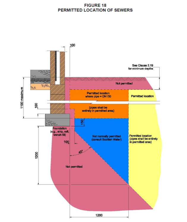
Hi Richard. You're going about this the right way. Yes good info and probably the starting point really to make progress. I have designed a few solutions for build over permission where we have a run of houses with the public sewer running up the back of the houses, very similar to yours... it can be done with a fair wind. In some ways having the old combined system can be a blessing as you only may have to make one connection and maybe blank off other existing ones. However, depending on where you are some water companies are not keen on you adding rainwater flow to the combined system as this exacerbates the problem with stormwater overflows spilling into rivers. At some point they may or may not ask for flow calculations. Leave that for now as it is in itself a lengthy topic. There are loads of folk on BH that know a lot about this, ask if you need to. For all... generally. A private sewer is a drain you do not share.. you own it. A public sewer serves more than one house and generally the water company own that. These public sewer run into main sewers.. often the big one in the road. In this case the drain being build over is a public sewer. There will be branches in the public sewer that connect into your bit of drain from your own house. You generally own (private sewer) the upstream bit from the branch socket. Also, as this is a combined sewer your rainwater pipes will be trapped and then connect into the public sewer. This is relevant later once you get into the detailed design as you often find that the trap and other connections start to obstruct founds etc and you compromise the ability to rod the drains. You may be lucky and find that the rain water down pipe serves both houses and the trap is on your neighbours side. I recently designed something like this in Scotland, similar rules apply in parts of the rest of the UK. This is the Scottish Water compliant method I used to get the build over permission. The line of houses were on a slope and the gardens were terraced. The manholes were away from the site.. I could roughly figure where the drain might be but not how deep as did not know the fall and also folk had been regrading the gardens over time. 1/ @saveasteading, yes I got the plan which indicated the MH covers and invert levels. That got me on the ball park. The main thing to recognise is that the record plans are often far from accurate and ofetn incomplete. 2/ The Client knew that the neighbour had a MH cover in their garden that was not buried under flower borders etc so after asking nicely we were allowed to lift the cover. Good news the invert level was not too deep. The year before I had one where we lifted the cover and could nearly see Australia. After a bit more investigation we abandoned the job as the drain was so deep it needed an expensive structural / gorund solution to deal with that and a couple of other things that just made the project uneconomic. At least we found out early on! Everyone was dissapointed, including me. 3/ Next was to get an approved Scottish Water company to do a CCTV survey. This was one of their (SW) requirements. We put the camera into the neighbours MH and fed it uphill to about 1.5m beyond the far boundary. The equipment they use is pretty good. Now we knew the line of the drain and the depth to about + / - 200mm. We could also see where the branches were connecting in. Importantly we were able to assess the condition of the drain and how good the joints were. Some of the joints were leaking and there was a bit of ground water seapage into the sewer. You could see a couple of little water spouts! Anyway the CCTV guys said.. not bad and the drain looks ok, SW should be happy with that. The CCTV folk do a formal report, a sketch plan with some dimensions. They also send a natty video and at the bottom you can see the calibration so you know where the camera is. The camera gets a bit of a hard time as it's amazing how often folk flush their toilet. This give you confidence to make the next step. 4/ We next hand dug a pit to check the CCTV info. Found the drain and the rainwater pipe trap which was bang up against the boundary retaining wall. Because the drains were at an angle it was clear that we needed to design the founds for this. But at least we knew what was what and could plan for that rather than risking problems during construction. 5/ Next was to design the drainage layout, prepare the drawings and then submit the CCTV survey package and the drawings for SW approval. Part of the approval was conditional on us getting a post construction survey. Screen shotted below is part of the build over approval so you can see what kind of thing the water companies are looking for. Ok that is.. call it the permission side / admin. But what sort of drawings do you need and how to design a build over up the back of of say @Richard Marin's house? My starting point is to go to the Sewers for Scotland guidance. It has a diagram that shows the zones where you can do stuff. You'll see lots of similar diagrams produced by water companies over the UK. Next was to marry this up with the site levels, look at options and get the best drain layout that suited the actual thing we wanted to build, in this case a rear extension. I have attached the two drawings that were submitted along with the CCTV survey to support the application for build over permission. I have edited them a little to remove identifiable info, if I have missed something can folk let me know? All drawings need a title box, sometimes it's good to let folk turn on and off the layers if using pdf. There is a fair bit of useful info on the drawings that lets you see the level of information that results in a good application. Hopefully they give you food for thought and point you towards what you need to know about your project. Please bear in mind though.. there is a bit of my IP in there which I don't mind sharing as I learn loads from BH and enjoy the enthusiasm here. One important thing is that these drawings show part of the foundation design. What they don't show is the structure above and how that fits with drawings you see. For example the drawings take into account the loading from above, building stability, soil pressure bulbs, what impact these will have on the existing house founds and the retaining wall adjacent to the existing house founds. In other words don't just copy the info and hope for the best.. or you will end up in trouble. Just to finish. You may be thinking.. is this overkill from Gus and how much does is that type of application going to cost me? Cost.. not as much as you think... probably the wrong phrase to use if in say Yorkshire. Good planning like this keeps the build cost down and reduces the risk of the unforseen. The dreaded "invoice from the builder for extras".. which they have a habit of submitting when they know they have you over a barrel, risk is reduced. But also you put loads of time, effort, invest your emotions.. and money into something like this and do it right. But what if your neighbour builds out the back, they are gung ho, damage the drains and put your extension at risk.. Oh.. now that post condition survey suddenly comes in handy, especially as it went 1.5 m beyond your boundary. Think of this CCTV survey as buying a bit of insurance. @Richard Marin Hope this gives you a bit of insight and allows you to pick the best bits that suit you and disregard the rest. Keep us posted and all the best with the project. DRG-SW01 Foundation and Drainage Layout A2.pdf DRG-SW02 Rev01 Drainage and Cross Sections A2.pdf

 1 point
 -
+1 . Buried posts will be easier!1 point
-
So we now know that this is a 150mm diameter combined drain (ie carrying both rainwater and sewage. And that in nextdoor's garden there should be a manhole cover The water company will have this same drawing, with additional info. Ask them for the full drawing, and btw isn't this sufficient to deal with their own question? Anyway you need the full drawing from them. It will have a table with all the drain and manhole cover levels1 point
-
This is inside the ICF, so no shuttering to remove, I did use some timber battens to protect the ICF from a vibrating screed. These are obviously staying where they are.... off to water the edges of my slab 😁1 point
-
Firstly look at your deeds, just in case Annoyingly the next dource is the drainage company, so it seems they don't know. Maybe phone and ask. Next, you draw it yourself you may need your builder to lift manhole covers, especially if in the road. Come back for more info of what you will have to look for and report. Do you at least have info on the drain you want to build over? Posting it on here would allow more help.1 point
-
A like is insufficient. Brilliant rock snd thanks gog thd info. Don't eorrh zbout the visible fibres they zcuff off under the tiniest ftiction eg foot traffic. Also the concrete finish looks fine. Try not to look at it and the appearance will improve. Some of the messier areas are surface laitence or froth marks from the coating. Does your varnish completely seal the surface or do you need to wet it again? The shrinkage cracks will be starting about now. Do not panic if there are any rogue ones. A minor thought.....the shower and bath drains could go to local soakaways as Grey water, if that helps in any way. Brilliant work though. Well done indeed.1 point
-
It’s a bastard for cracking too, so it needs to be allowed to dry slowly. When I plastered a room using NHL I damped it down a couple of times a day for the first week too.1 point
-
Got as far as filling a bucket with nettles last year after a tip on here. Promptly forgot about it until it dawned what the smell was! Then the bucket dried out. Seem to recall you're supposed to dilute 10:1 as it's strong stuff. Just given the soil around each plant about 100ml of this made up, organic fertiliser:
 1 point
 -
Mould dies when the dampness is removed. You still have to find the source of the water.1 point
-
Looks good to me. Diy fertiliser has to be best. When it stinks so badly it must be effective. For new readers. Collect weeds especially the succulent green ones like dandelions and nettles. Place in bucket and compress. Fill with water and weight down with anything 2 weeks or so later it will be brown and stinky. Decant into a large plastic bottle, or lots of small ones. Use slightly diluted.1 point
-
For OP - if going for hydraulic lime it is crucial to wet the wall properly first. In hot weather that means soaking the wall with a hose, get the mix on and probably wet the wall again prior to laying on. You will be amazed how quickly the wall will dry out after being soaked.1 point
-
@SteamyTea the bloke who wrote that is wong... Seriously though, point taken though a bit late now On the effectiveness as a slug/snail deterrent it's either that or the garlic water that's keeping them away it seems. Only two plants out of 50 have been nibbled and I found the culprit on one and dealt with it (small slug). I've also been putting human hair around the plants. If the caffeine is having a suppressing effect I wonder if it's worth giving each plant a liquid feed now?1 point
-
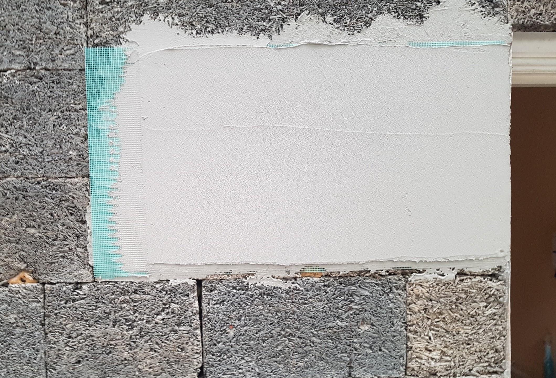
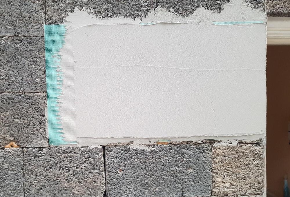
Just in case some readers aren't sure what 'meshing' is, here's a photo in this case applied to an ICF. The mistake I made initially was to try and apply the mesh when the first coat of render was already too dry, and the other was trying to apply it to a too first thin coat. Oh - and the weather was way too hot, and I didn't pre-wet the wall enough. Anyway .....
 1 point
 -
Maker Why used coffee grounds may be doing your plants more harm than good We are often told to add used coffee grounds to garden soil to perk up plants. But the science doesn’t support this, says James Wong 14 June 2023 By James Wong DGLimages/Alamy WANDERING around an achingly cool San Francisco coffee shop a few years ago, I was fascinated to see huge, open-topped barrels filled with used coffee grounds and a sign saying they were free for customers to scoop into recycled bags and take home to perk up their plants. I realised that we had reached peak hipster. Indeed, the claim that coffee waste dramatically boosts plant growth has been a staple of organic gardening books since at least the 1970s, and seems to be seeing a modern renaissance. Proponents everywhere wax lyrical about how the spent grounds are not only rich in nitrogen – a key plant nutrient – but can help lower the pH of garden soils for species whose roots require acidic conditions, like blueberries. It all sounds like such a brilliant idea: upcycling industrial waste into free, organic fertiliser. It is just a shame that in reality it is probably doing the exact opposite. Let me explain… Coffee grounds, even after brewing, are still a rich source of caffeine. This compound seems to be produced by coffee bushes – at least in part – as a herbicide to suppress the growth of smaller competing plants. The phenomenon is called allelopathy and is a strategy loads of plants have evolved to help reduce the competition for light, space, water and nutrients around them. Leaching out of the grounds, the highly soluble caffeine percolates through the soil and has been repeatedly shown to severely stunt the growth of small, neighbouring plants’ roots and slash the rate of seed germination, even at relatively tiny concentrations. Not exactly what the plantfluencers of social media promise. The weirdest thing about how often this tip is recommended is that we have known about the allelopathic potential of caffeine in coffee plants for decades. The first paper I could find on this was from 1980, and its conclusions have been echoed by study after study. So effective is caffeine at suppressing plant growth, it has been investigated as a potential novel herbicide for agricultural use, both in the form of direct application of coffee grounds on farms in Brazil and even tea leaves (which also contain caffeine) on plantations in Vietnam. This effect is so pronounced that over years of intensive cultivation, the accumulated caffeine in the soil of long-established coffee farms can reach levels where it doesn’t just hamper the growth of small weed seedlings, but even the mature coffee bushes. Studies have been conducted to see if underplanting coffee with more resistant herbs, like sage and oregano, could help reduce the caffeine contamination in the soil by drawing the compound up through their roots, while providing farmers with an extra crop to harvest. I wonder if the world is ready for caffeinated herbs. But that’s another matter. James Wong is a botanist and science writer, with a particular interest in food crops, conservation and the environment. Trained at the Royal Botanic Gardens, Kew, he shares his tiny London flat with more than 500 houseplants. You can follow him on Twitter and Instagram @botanygeek For other projects visit newscientist.com/maker.1 point
-
1 point
-
I direct mix of hydrated lime and sand won’t set, no. It’s often used as a practice mortar for that reason. But it can be made into a putty which will1 point
-
This is the current thread on the topic. @S2D2 installed his using vacuum pump, I did mine without. Post questions over there 🙂1 point
-
Please don’t use hydrated lime and sand - it won’t set. I would definitely use NHL 3.5 not hydrated/cement myself. ratio 3:1 sand:lime if your chap is fine to take a bit of time to do it should be fine.1 point
-
Jeremy is not about anymore, but there are a few others that have recently fitted them. Have a hunt around and you should find it. Try a google site search, it is much better than the forum search facility.1 point
-
I've used Tikkurilla paints internally who publish SD values and are reasonably priced. Yes, I'd you look at Google steet view for my house in 2009 it is brown unpainted sand/cement, which I reckon was possibly nearly 100 years old. In 2016ish it was painted with homebase masonry paint (I know this as owner left the spare tub in the shed). In 2022 we then had penetrating damp with lots of cracks on render and spalled bricks underneath.1 point
-
Interesting comment. For us, your comment come just in time. What rouses your suspicion, and - let's assume your suspicion is correct - which paint (or type of paint) would you suggest? Is there such a thing as breathable paint ? PS Apologies: I've asked a question I could have answered for myself Here's a list of external, breathable paints https://ggle.io/5uX3 Thank you @larry very much indeed for raising the issue. Helped me avoid a possible error.1 point
-
Salus auto balancing valves can take an hour or so to calibrate. Did you have heat to the manifold, if you didn't the valves have nothing to calibrate themselves against. It looks like you are trying to bleed the system also, do things logically. Take actuators off, install hand valves that came with the manifold. Open all valves fully - Bleed system. Ensure heat source is fully working, pressurise system, bring hot water into system, this will chase the final bits of air out the system bleeds. Check for leaks. Run manually until everything has warmed up. Check for leaks again. Switch off. Now look at the electric side of things. Tidy all the wiring up. It looks a mess. Reset your actuators per the instructions, so they go though the commission process again. Power up do a call for heat on all circuits leave it to sort it's self out for an hour or so.1 point
-
No you can do it direct with OR now. https://www.openreach.com/building-developers-and-projects/fibre-for-developers/registering-your-site Because of the BR change (Jan 23) they have opened it up to all new builds, not just large developers. Nice little money spinner I'm sure.1 point
-
Sand lime acts like a sponge and will never set many years ago when was an apprentice Sand lime and putty lime was what we used at collage We would plaster walls and the following we knock it off the wall and chuck it back in the mixer and reuse Week after week Even a spade of cement will help bind it together1 point
-
It depends on the manufacturer. There's no real standards when it comes to NHL, so one NHL 2 might be entirely different to another NHL 2. If it was me, given you say the bricks are pretty soft, I'd be using a lime putty based render, rather than NHL. There's a couple of Facebook groups that are really useful when it comes to older properties; "Traditional and Listed Building Advice" and "Your Old House UK - Repair and Conservation" I've learned a lots from both.1 point
-
I'm using a 9kW ASHP on a smallish thermal store, so we don't have a massive amount of *stored* energy until there's plenty of PV diverted to it. Nevertheless, the tank never runs cold and the heat pump will cut in and recover seamlessly. Less than an hour will recover the tank.1 point
-
Can you add them on the DC side, will need a charge controller between the modules and the batteries, but should need nothing between the batteries and a regular inverter, just a case of pumping in the correct voltages.1 point
-
I was genuinely going to record it anyway as I do all council stuff . So I can hang them if need be and also prevent myself saying stuff I should ( not ) .1 point
-
We used Hardie Backer board and stone photo above. Too heavy for young kids to lift and held down by the flush plate anyway.1 point
-
Look around for your nearest stone worktop supplier. They are usually more than happy to get rid of the stacks of small bits of stone they have cluttering the yard. I'm sure they would put a polished front edge on it for you for a few quid. The other point is that you can if you want have behind the loo fully tiled, and a small duel push button off to the side. I hate those bloody huge push plates, that are right behind the up toilet seat.1 point
-
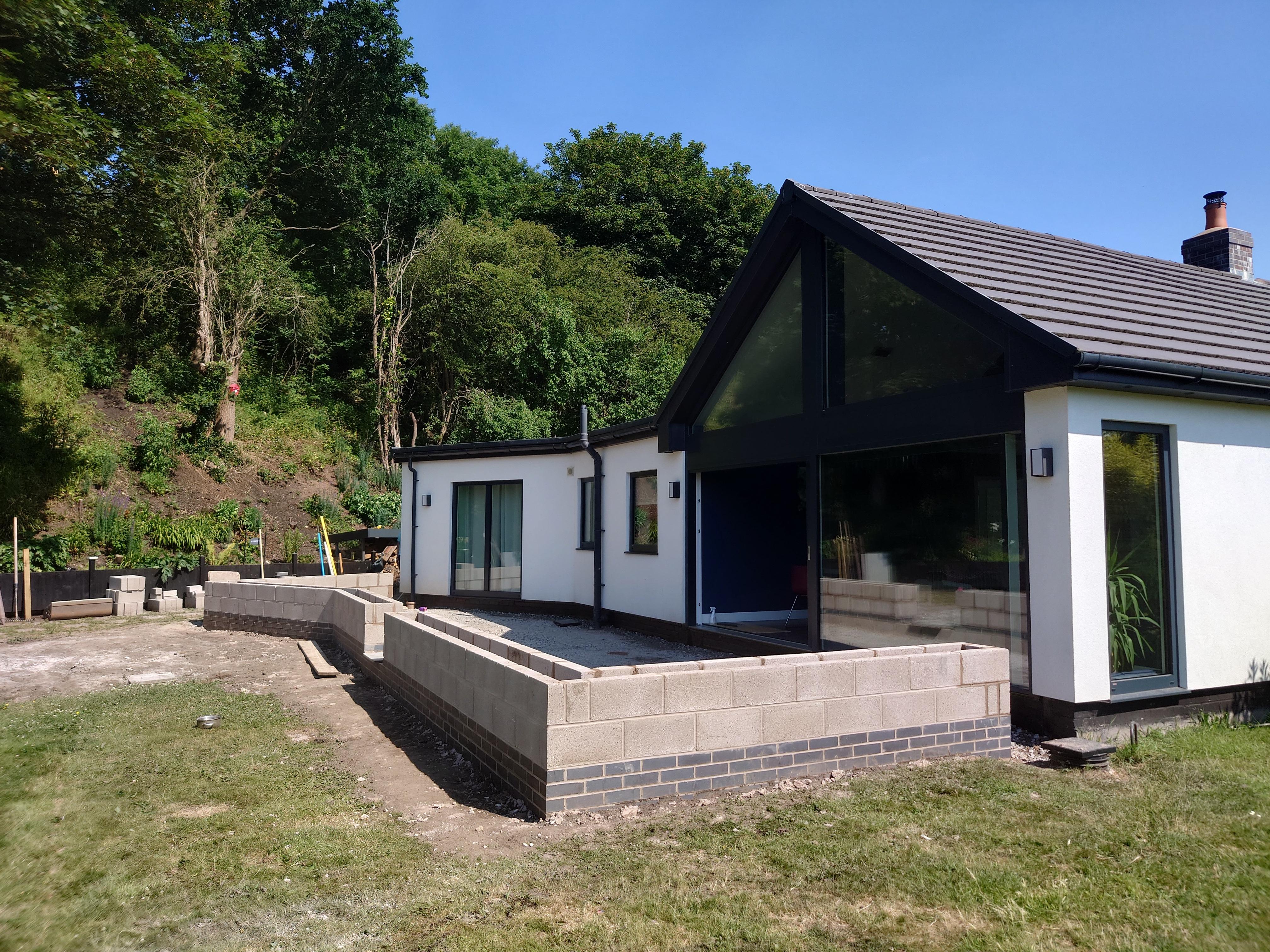
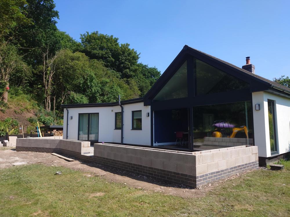
@S2D2 we haven't got the porcelain laid yet but it will be below the blue brick inside and the height will be 50cm from the bottom of the blue brick. Ground needs building up levelling outside planters and the white render will match the walls yet but here's some pics. We also sorted our porcelain. All 100m2 of it with 'a bit extra thrown in' for £2200 (we are having another patio area with gazebo). It's like a smooth almost granite like effect.


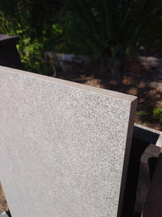
 1 point
 -
If 3-phase is close to the cost of a single phase connection, then get 3-phase, just to future proof extra car charging, or whatever else. Three phase will make it easier to have more PV on the roof as well.1 point
-
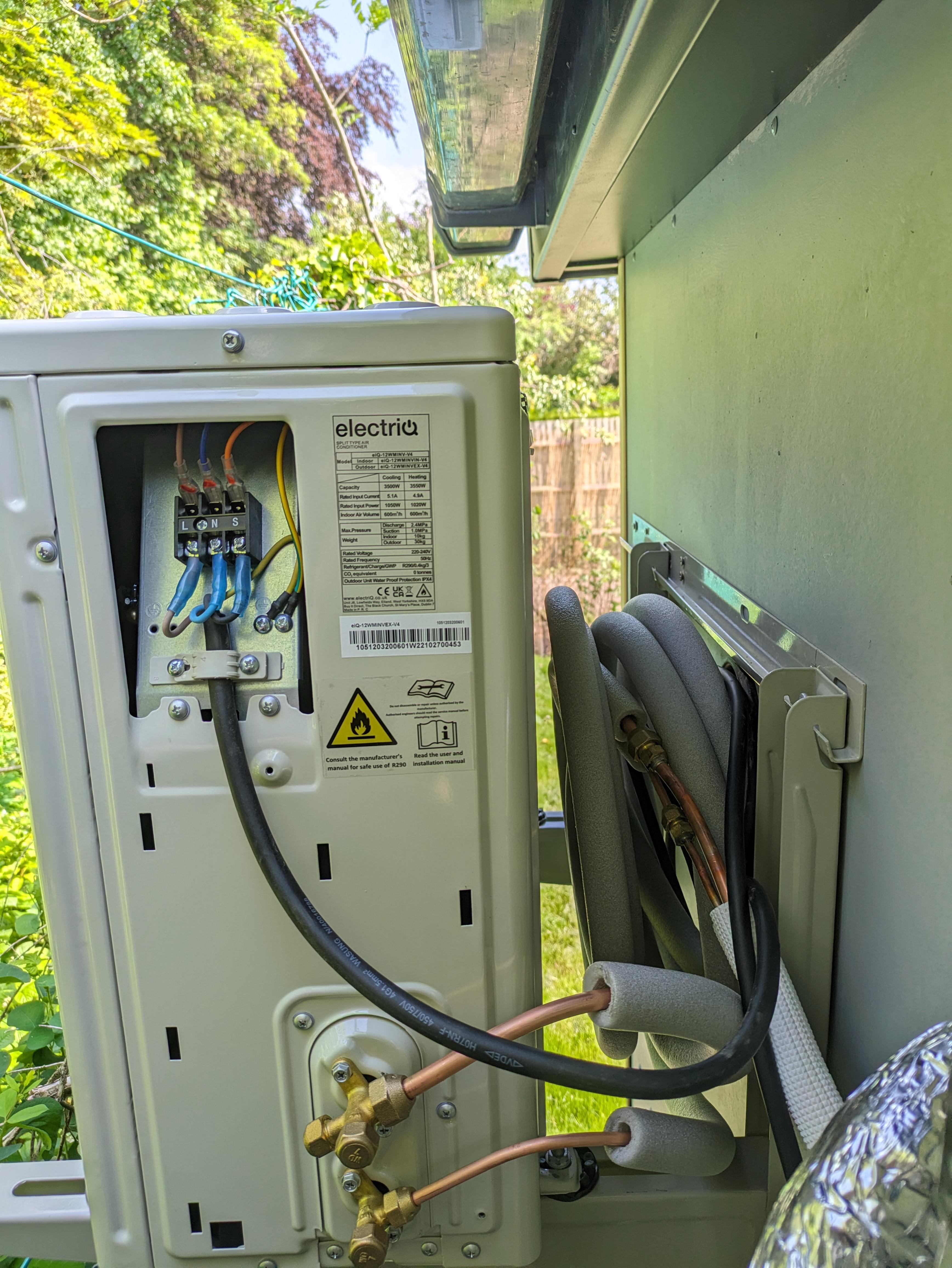
Many thanks for the tips! @S2D2 (I also found a 27 page Nowty thread on that other forum but it rambled all over the place and I gave up trying to find anything on this topic) The coil of spare pipe seemed in elegant but I went with it as path of least resistance. Shoved some misc insulation and neoprene jacket over the numerous joints and exposed pipework. The air bleed process was simple (if a little unsatisfying as there's no feedback I'd done it right) but firing it up all working well. It sat humming for 10mins before really getting going not sure if it has some initial self test or it'll always do that. Now I have WiFi in the room with it, I can try and get the app setup too.

 1 point
 -
IMHO it looks a bit tight. Think circulation space around your table, do people need to squeeze past the window or planter side when those chairs are occupied? I would add another 1m to the width.1 point
-
It may be worth considering metal studs MF It’s a lot easier get get straight and square and much lighter to use Also it’s make’s plumbing and electrical work much easier due to cut outs already being in place1 point
-
yes, a length of 4x2 on floor and another on the roof, you may need noggins in between the rafters to take it.1 point
-
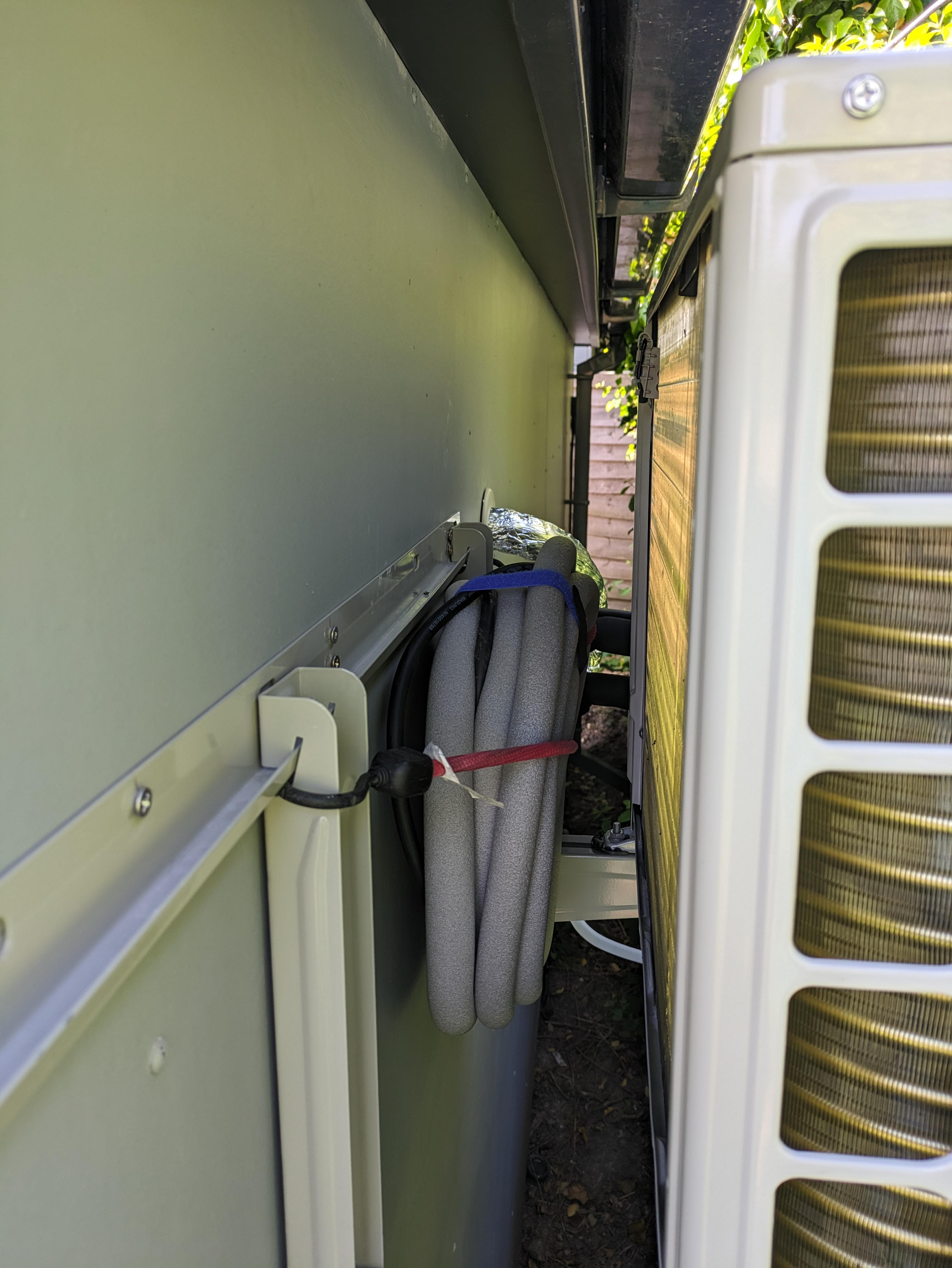
Anyone else installing one, note the illustrations and the installation text don't entirely match. E.g. the text says to install the protective sleeve in the hole cut through the wall, and to wrap the pipe bundle in additional insulation, prior to passing through the (sleeve in the) wall. The diagrams don't show either those steps, nor does the kit include said sleeve or insulation. So, anyway having noticed this I managed to get mine back off the wall and wrap the pipes. I used self-adhesive foam and then a layer of self-adhesive aluminium foil. The result looks OK enough, and importantly the bundle passed much more smoothly through the wall than it did as separate pipes/wires. Next up is mounting the external unit ona wall bracket.
 1 point
 -
After 35 years experience buying a multitude of garden furniture......it's not about the price you pay it's ... about the time and effort you invest and spend in preserving them.1 point
-
Thought I'd round this off with a bit of info on running costs. The last few days have been fairly Windy in the static, and the heating has been used a lot. I bought a plug in WiFi energy meter to have a look at the power usage. Below is the screen shot. It seems to use between 5 and 45 watts in standby. The unit was in standby when this screenshot was taken. And using 7.03W. I'm quite happy. We run the unit to set temp of 20 Deg and leave the internal doors open In the static to try to get the rest of the van warm. Appreciate anyone's thoughts on this.
 1 point
 -
And since then my plumbing has never been wrong 😉0 points
-
Yeh the ties with the condoms that's what i've used with cavitiy ties every joint on the blockwork0 points
-
“Who’s coat is that jacket” is a close second. 👊😎🏴🏴🏴0 points