Leaderboard
Popular Content
Showing content with the highest reputation on 09/06/21 in all areas
-
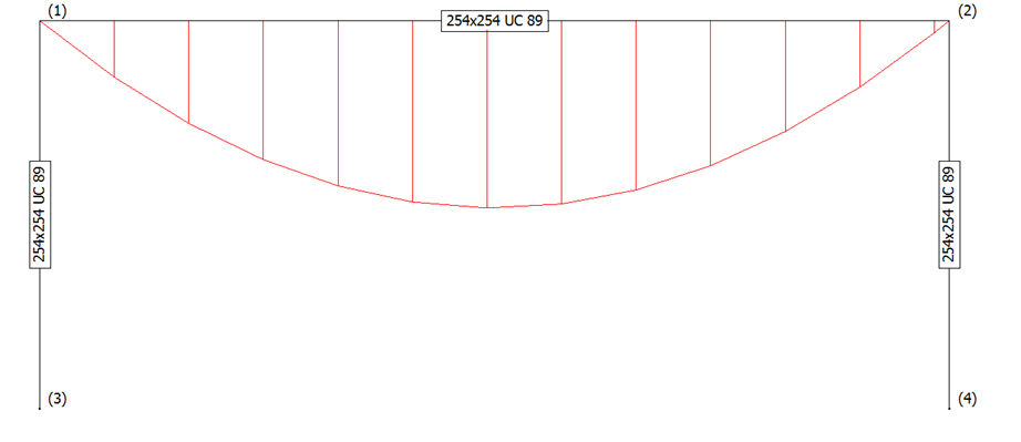
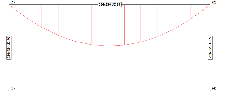
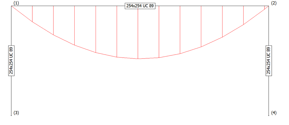
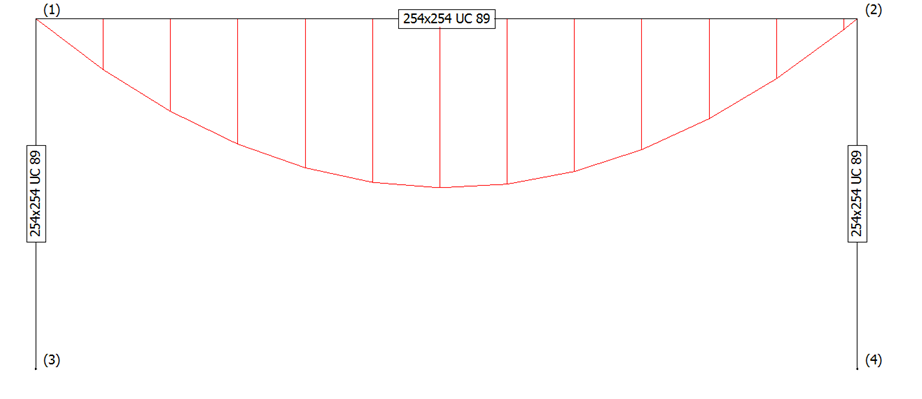
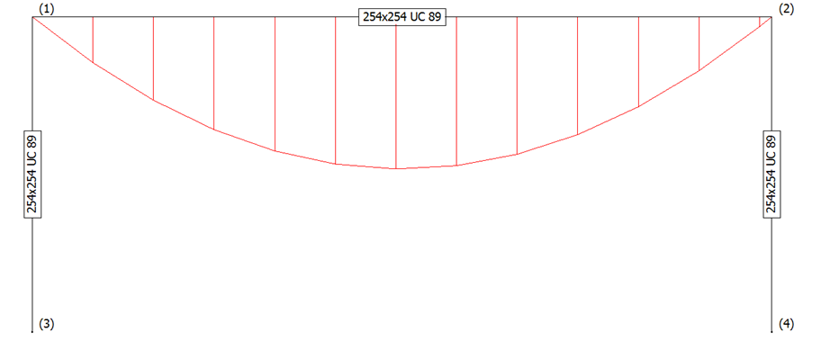
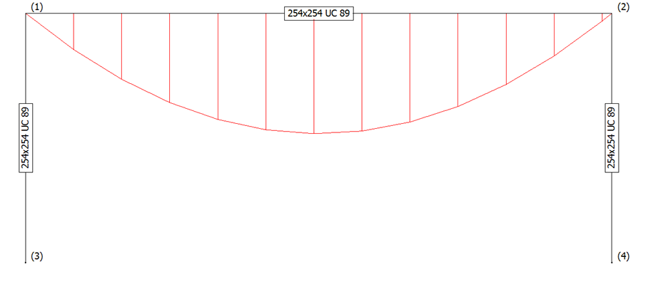
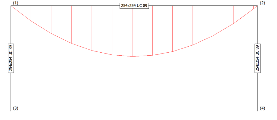
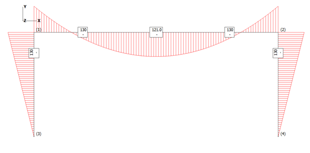
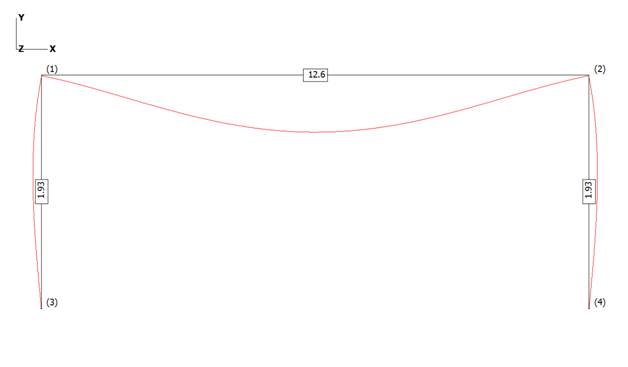
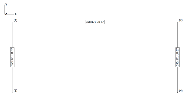
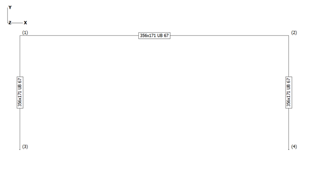
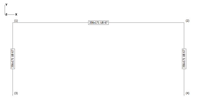
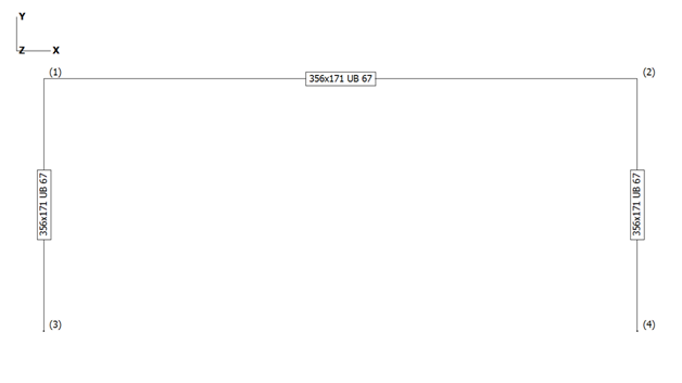
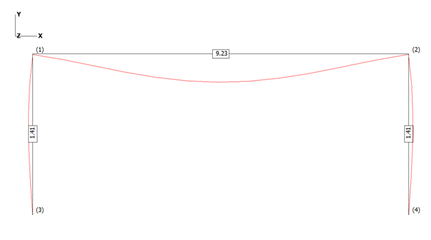
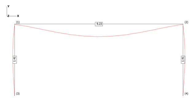
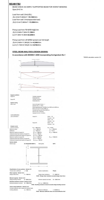
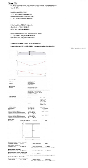
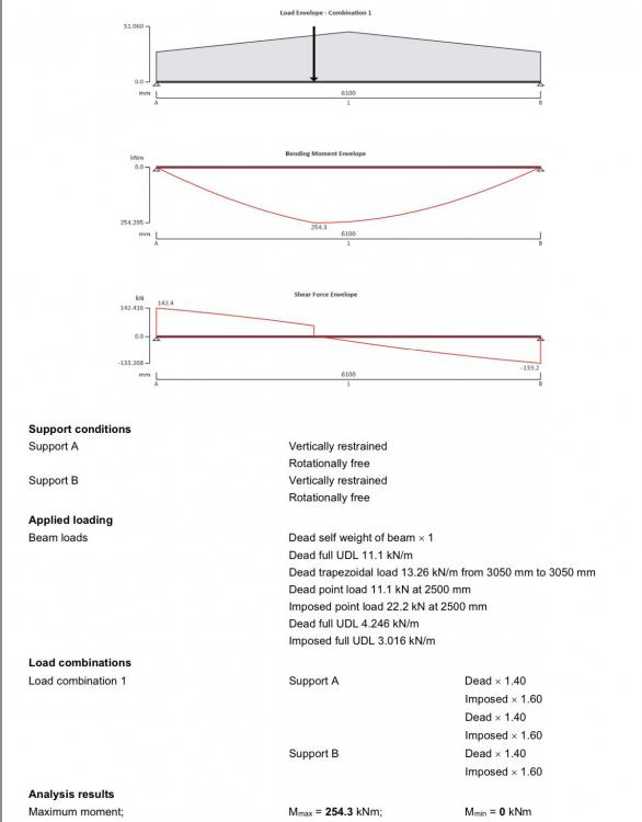
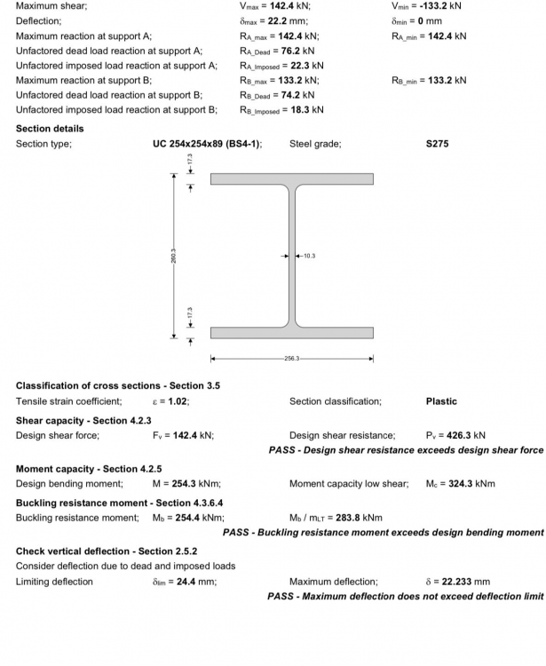
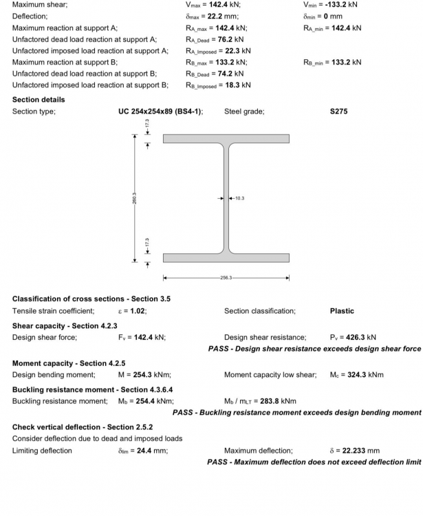
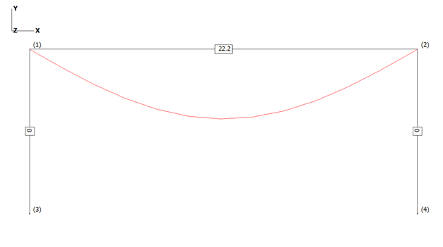
End of Cover Page Hello all and @Heather85uk Bifold doors, sliding doors, deflections and goal posts! Hopefully this part overview will help some BH members weave their way through what can be a bit of a mine field, but exciting too once they are installed and working! I have linked to Heather’s post as Heather has provided a few calcs (copied below) from the SE and in the spirit of BH I have taken the liberty of adapting and simplifying Heather’s calcs to “tell a story”. Heather, I hope you don’t mind. @Heather85uk There is plenty info on BH about limiting deflections and other good practical stuff, but I hope that it may be helpful to take a few steps back to see what causes these deflections and how you can start to get a design to work. Although the post is about bifolds, sliding door openings much of the following can be adapted by anyone who is contemplating making a hole in their house and needs a beam and/ or some columns to hold things up. Lastly, before the nitty gritty / the following is very much a simplification. Please don’t “ladle” into your SE as often there are other considerations to account for. Most SE’s should be willing to explain so just ask.. If they can see that you have put some effort into grasping some of the basics then they will often return the favour and more. Also, if you can get your head some of the concepts I hope it can help you get what you want at a reasonable price. Maybe, the following will give you more leverage when negotiating with door, glazing suppliers. To get started here I have taken Heather’s calcs and simplified the loads as it makes it (I hope) easier to get a feel for things. I have used these calcs as the deflections seem a bit “off”. A good refreshing thing I find about BH is that it’s a forum for solving potential problems. Heather’s calcs show a beam that is what we call simply supported. Imagine (I’ll ask this as this seems to be a common trait we share on BH) you have a ruler and prop each end on a pencil. Load it up and it bends. The pencils at each end allow the beam to rotate at the supports. This is called a “simple support” The diagram below is what we call a bending moment diagram and this represents the bending force in the beam (ruler). You can see that the largest bending force occurs in the middle, just like the ruler. You know intrinsically that if you overload the ruler over it’s length it will often tend to often snap in the middle where the largest bending force occurs. You can also see that the bending force is 251.2. The units are kilo Newton metres (kNm) and are close enough to Heather’s calcs for practical purposes. The diagram below is what we call the deflected shape. This is pretty much a representation of the shape the beam will take up when you load it. It’s a little different on the curve from Heather’s as I have converted the point loads to uniform loads. The deflection value of 22.2 mm is the amount the beam will bend in the middle and is close enough to the value shown in Heather’s calcs for the story! What we have above is similar behaviour to say a concrete lintel, a solid timber floor joist, a metal web joist and so on. The key thing to draw from this is that when a beam has a simple support at the ends it forms a shape like this and has a distribution of bending forces parabola shaped. If you have point loads then the parabola gets distorted to a greater or lesser extent. Heather mentions a “goal post”.. two uprights at each side and a beam over the top. Often you find that when you have a big opening you can get some onerous loads. Heather also has some point loads (maybe floor transfer beams framing in) near the middle of the beam span. Often you find that while you can get a beam to work, when you come to check the supports at the sides you find the masonry or timber frame holding up the ends of the beam can’t do the job. You can look on BH about pad stones, cripple studs and so on so I won’t explore further. One solution when the side supports can’t carry the loads is to introduce steel to form the sides, you form a “goal post” and take the load down to the foundations zone using steel which is good in compression, thus you relieve the load on say the masonry or timber frame at the sides of the opening. Steel is good at performing this function, but as there is no free lunch you often get more thermal bridging and you have to fix the steel to the rest of the structure, be mindful of that. Here (below diagram) the sides of the goal post only serve to transmit the vertical load and relieve the load say on the masonry or timber frame. I have replicated Heather’s beam below but with the same size of posts (columns) each side to form a goal post as it’s easier to make a point. “Don’t do this at home” as in detailed design you would balance the sections to match the bending and other forces and so on. The beam is still simply supported so you can see that all the columns are doing is acting like the “pencil supports” and holding up the ends of the beam. There is no bending force in the columns. They only carry the vertical loads from the beam ends down to the bottom of the goal post. The diagrams below show the bending moment diagram and the deflected shape. You can see that introducing the columns as simple supports has made no difference to the deflection. Still 22.2mm as we still have simple supports.. the pencils. We would hope that the ends of the beam and the columns are bolted (fixed) together in some way, if not you need to ask why not? But.. we can connect beams/ columns together in different ways. For example you can use a thin metal end plate on the top beam which bends like an elastic band (that is what I have done above and is called flexible connection) and then recovers (steel is quite bendy stuff!) so this maintains the idea of a pinned connection. Or, you can use a thick plate with bigger bolts, alter the welds etc. (if need be) which makes the connection rigid..a rigid connection. What I have done below is to keep the same arrangement of goal post / beam but changed the beam end connections from a pin to a more rigid connection. The first diagram shows the section sizes. Again, the sections I show are not quite what you do at the detailed design stage but I hope it makes the principles easier to follow. At detailed design you look to see what you can cut from stock lengths, the weight of steel and so on. The bending moment diagram below shows what happens when you change the end connection from a pin to a rigid connection.. Here you can see that by rigidly fixing the ends of the beam to the top of the columns we have reduced the bending effect in the middle of the beam and are asking the columns to now step up to the plate and do some extra work. The columns are now carrying some of the bending force as well as the vertical load from the ends of the beam. This relieves some of the bending force (moment) in the beam and this also reduces the deflection over the doors. Below is the deflected shape with the deflection value. By changing the type of connection at the end of the beam we have reduced the overall deflection from some 22.2mm down to 12.6mm. Getting closer to say Express Bifold deflection spec but still a bit off, but closer, nearly there! What we are doing here goes back to the ruler concept supported on a pencil at each end. If you had three hands then you’ll find that if you can stop the ends of the ruler rotating then it will bend (deflect) less in the middle. The columns act as two of your hands at each end of the ruler, imagine the third hand is applying the load to the ruler.. Nod, markc MickSharpe01 et al.. good points about beams sizes , the loads, hit and miss welding.. plenty good stuff to digest from them and others. Let’s now look at how you may go about getting something to work with Heather’s loads. Below I have picked all the same section / stock sizes, which means that you have a better chance of getting the connections to work and reduce wastage when you buy the steels.. go for the lightest weight of steel at the conceptual design stage and you’ll often run into trouble at the detailed connection design stage and it will end up costing you more. Often if you plump for the lightest beam then the flanges / webs are too thin to resist the localised forces from the bolts. You then end up having to design a complex connection with stiffeners, more bolts and the fabricator will charge you a lot for this extra work, often more than just starting out with a heavier off the shelf beam. As an aside. This is a good example for the self builder renovator. Sometimes it’s much better to go for the “simple stupid” .. stock steel sizes and simple connection design although initially you may feel you are using more steel. You should save money on fabrication and steel erection costs even though you may have to use heavier steels. Below is the deflected shape with the different (356 x171 x 67kg) set of sections. You can see that we are now down to some 9.2mm overall deflection. Yes, we have a bit more steel weight but we are looking for the easy way, stock items, that will also save on labour while considering that we are self builders rather than a large commercial outfit. What I have done above is to change some of the sections and connection types to show what you can do. The top beam is deeper and I have reduced the deflection down to 9.2mm over the 6.1m span. Feeling hopeful! Heather’s loading is roughly split (before applying safety factors) 50 /50 between live and dead loading. This means that as you are building the beam it will bend as you build up the floors and add the walls over the beam. Before you place the order for the doors you want to make sure you know the true opening as built sizes which will include the dead load deflection. Remember here.. your need to cut the brickie some slack. If they can get each side of the opening level to within 5.0mm that is good. A good brickie should be able to sweeten out the coursing too over the beam. Lastly we are using hot rolled steel beams. These too have a manufacturing tolerance and are not truly straight! Bearing the above in mind. Half of the 9.2mm deflection will take place before you order the doors. The other ~ 4.6mm when say it snows or you have a massive party and load up all the floors with live load. Express say 3.0mm not far off the 4.6mm! But the 25mm in Heather’s calcs? Hopefully the above has given you a flavour of goal posts and what you can do. Now one other thing that crops up in Heather’s calcs is a fairly high loading on the beam for a domestic application. You’ll see this in the calcs as being 142 kN. That is about 14 tonnes. This load is expressed as including the safety factors. Without the safety factors the load at the end of the beam will be about 100kN.. that is ten tonnes.. 10 old Volvo cars, not a small load. The load has to be carried by the founds. I hope this helps folk get a feel for goal posts! If you have an old house or say a house on piles and want to form a large opening then you can take the above principles and turn the goal post into a box frame. A box frame can also further reduce the top beam deflection and spread the load on the founds. In simplistic terms you take the load from above, down the sides of the goal post into a stiff bottom beam. This beam spreads the column loads out so the old founds “still think” they have the old wall above. Box frames are also good at resisting the sideways wind loads. I’ll leave that topic for now.. a story for another day if there is any interest. Hope this helps to give you some pointers and all the best with your journey.4 points
-
Just to let everybody know, I bought 13 rolls of Tescon Vana tape from Latzel Dammstoffe for about 16 Euro each. A few points worth knowing: - Post brexit your order value with them has to be over 200 Euro. (They are not registered in some way for the below £135 scheme where VAT isn’t refunded). - They refund you the German VAT less a few fees (approx 25 euro in my case). - You pay the UK VAT and UK Import Duty to the courier before the parcel is released for delivery. Even with the additional charges, it’s considerably cheaper than buying the tape in the UK. The above is probably obvious to most but it was the first time I’d bought anything of any value from the EU post Brexit so it might be useful to some.3 points
-
One on the right with the Y laid flat and then a 90° elbow pointing upward. Will push the flow down the line. Upward tee is a bad idea.2 points
-
Hi all, sorry for the delayed response its been a busy few weeks. It worked anyway. I scraped the excess hardwood back with a fresh Stanley blade until the delamination would push down without resistance. Then I got a pic under the delamination to lift it just high enough to fit a 14 gauge blunt needle under and filled the cavity with cascamite. I then pushed it down wiped off the excess with a damp ragand weighed it down with a piece of damp first layer, then a 2"x2" tile with four 7n blocks on top for 24 hours. To finish it I'll rub a small amount of adheasive (same colour as the floor) into the slight gap but it's hardly noticeable then rub it down with a damp cloth. Worked a dream. Thanks all for your input.2 points
-
Do you understand why this gap is a requirement? It is so that ground settlement / movement ( heave ) etc never affect the pipe. Pipes set in without have sheered in half because this has not been observed. It has zero to do with the functionality of the pipe, this is to ENSURE its longevity. Tell the builder this, and tell him to rectify.2 points
-
Motor isn’t the main source of noise - the air flow is. Is the kitchen on the ground floor ..? If so you will have issues with ducting as you don’t want to create a “U” that can collect condensation / fat etc.1 point
-
1 point
-
If you mean a downdraft hob then they most likely recirculate. You need to know what hob you want to plan it into the kitchen - some of them the motor is huge.1 point
-
Yeah we spray it It goes on like water and soaks in quickly and doesn’t run It hardens the surface of the board You can normally coat a four bed house in a couple of hours1 point
-
I would not even consider having dot and dab, wet plaster (sand and cement first coat) was my specification from day one.1 point
-
We had a scheme with 88 flats with external metal balconies - the balconies were in Millboard but the terraces were in timber decking - passed it's EPS1 with no issues.1 point
-
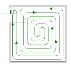
+1 Leave all loop valves open for the pressure test so a leak in any floor loop will show up on the pressure gauge. You might see some variation in pressure due to temperature changes over next few days/nights.1 point
-
1 point
-
Oops, just watched the video again. Was supposed to close the flow gauges as each circuit was filled, but didn't. And I was supposed to re-open all flow gauges and return valves at the end and see the pressure gauge rise. Will open all valves now.1 point
-
No, it's more to do with having sufficient pipe in the floor to get enough heat into the room. Rooms like kitchens and bathrooms that have a lot of areas where you can't run pipe can benefit with having a closer spacing to make up.1 point
-
I would probably reduce the spacing to 150mm and have 7 pipes in the 1200mm gap and 150mm separation from the units.1 point
-
1 point
-
That’s not for us to say It’s your BCO who may fail it, so pass the onus on to the builder VIA EMAIL and state that “on his head be it should it not be passed”. Make sure he knows you will not be footing the bill for any such subsequent alterations to satisfy BCO.1 point
-
Hello and thanks for your answers.... I have 140kg of stuff spread over about 5 positions. My flat is meant to be 45sqm so the loft is roughly the same, It's more long and thin with the longest dimension of the flat being 11.5 metres and varying widths. The actual beams are boarded over and insulated - I recall seeing some writing on the trusses but it was more about the plot number the truss was intended for - I'll take another look to see if there are further clues.1 point
-
Drains will work fine but the BCO may say no …! Not that difficult to sort now, pain in the bum to sort when there are 7 courses of masonry on top.1 point
-
cheers, it looks like its the FM330 https://www.illbruck.com/en_GB/product/fm330-pro-foam-air-seal/1 point
-
1 point
-
There is surprisingly little data on wind generation capacity during slow UK weather but I eventually found this covering the winter of 2020/21. The graph highlights periods when the capacity of wind generation dipped below 20% for a day or more. A quick scan of the graph suggests 4 sub 10% events last winter. https://www.drax.com/press_release/experts-issue-weather-warning-for-britains-electricity-grid/1 point
-
Illbruck foam for the 50mm void, check different types for suitability. The website is quite helpful. Use cement backer board eg 12.5mm Hardi / similar as the closure plate.1 point
-
If its in the Building Regs, then it must be adhered to as far as I can say. I wouldn't risk it for something so minor really.1 point
-
Buy one… the older IM350 is bomb proof and is only £45 to have fully serviced. You can buy them for £200 or so on eBay, at the end of the build you can have it serviced and sell it for what you paid. It will pay for itself many times over.1 point
-
Yup. Keep the 8bsr incoming and take outside taps off direct, reduce to 5bar and pick up WC’s and cold fed appliances, and then have the house at 3.5bar balanced. Are you fitting an UVC or a combi? Other?1 point
-
we also looked at these when looking at Internorm windows but in the end decided not to go that route for some of the reasons @ProDave has mentioned but also when doing the maths it was cheaper to get external blinds integrated into the building which we thought was a better solution.1 point
-
I suspect the quality is heavily dependant on the window manufacturer? I did look in detail at a similar system fitted to a house up up the road from here. These were Nordan triple glazed windows with integral blinds. The devil is in the detail. To my mind they were really double glazed windows, with the blinds on the outside of the DG unit and then a single pane of glass over the blinds. The outer layer of glass could be hinged open to access the blinds for cleaning or maintenance, but that of course means is is not sealed so I doubt the window would have the performance of a true triple glazed unit. Also the strings to operate the blind have to pass through a hole drilled through the frame to get to the insides. It all seemed to compromise the window. There were other issues with that particular window design as well that also put me off.1 point
-
We thought about these but decided against them because at some point one will break and thus ruin the whole window.1 point
-
Keep the 8bar pressure for your outside tap(s) or onward feed to outbuildings etc. Go stopcock, outside tap then reduce afterwards. It's only what our very own Welsh Wizard @Nickfromwales told me. I too have 8bar coming in. Does mean you have to check/tighten your garden hose connections now and then and as required clean your prv mesh filter.1 point
-
Ask your SE how they feel about the following. Lift the existing boards, clean the top of the floor joists, wire brush , hoover the top so that you get a good rough clean surface. Apply a liberal amount of structural glue to top of joist. Pilot drill and counter sink holes in ply and screw fix down to top of joists at 200mm centres. Glue to be a true structural glue such as Cascamite.. not D4 as a popular on BH. The screws are to provide the compression while the glue hardens, the glue does the work. Now you have turned the joists into a quasi "T" beam. The SE will probably need to do some calcs by hand (a few pages mind) as you don't get off the shelf software for this, and also, as it's a bit off the wall they may need to spend some time "researching ".. great job for a graduate though wanting to build their portfolio as you have to go back to basics. Now you have your structural deck. Give it a bit of time to condition, get the heating working. Next tile but use a decoupling matt? ... plenty info on BH from the pro tilers on how you do it. Lastly make it clear to SE and Architect that you will accept any liability if the tiles crack and offer to pay SE as you have "heard" that it can be quite complex to design. The SE may just say.. oh I have an old spread sheet that I used to use, give me a couple of hundered quid and you take responsibility if tiles crack. On short span floor like this tile cracking is much more likely to occur due to shrinkage (drying and swelling) of the substrate rather than deflection of the structural members.1 point
-
I bet that poor bit is really sore about being trapped in your groin. Photo please (Not often I piss Mods off now is it?)1 point
-
In July also the I-Beams for the timber frame and the OSB (or should i call it GOLD - prices went through the roof since i first had some quotes)arrived. https://tintabernacle.blogspot.com/2021/09/1-house-on-1-lorry.html1 point
-
This banner is here as part of the Keyfob offer, supporting young enterprise and the forum. You can find out more about HERE. BuildHub is a non-profit, self-funding forum, run by volunteers. We've grown steadily over the years to become the UK's largest (and certainly best!) self-building and renovation forum. While the unpaid contributions of our volunteer managers, administrators and moderators help reduce our running costs, we still have unavoidable direct expenses, such as software and hosting. Unusually for a forum of our size - we recently registered our 14,000th member - BuildHub does not accept sponsorship or run ads as a way of covering our outgoings. We therefore occasionally turn to you, BuildHub's wonderful members, to ask for donations. If you are able to make a financial contribution at this time, it would be very much appreciated. There is no minimum or suggested donation amount, and even a small donation will have a positive impact. Donations via PayPal can be made to the following email address. Please remember to select 'gift' / Friends & Family or Paypal will charge fees. fundtheforum@buildhub.org.uk You can also request the forums bank details, please PM @newhome for those details and let her know of your donation. We'll post again once we've received sufficient donations to cover expenses due in the foreseeable future. BuildHub's Treasurer, @newhome, manages our funding account. Could anyone wishing to make a donation please send her a PM with your email, username, and the amount that you have pledged so she can confirm receipt of the funds and log your donation accordingly? All donations will be treated as confidential. If you can offer any skills that may assist with the support of the forum, please contact either Herb (@HerbJ) or Mike (@MikeSharp01) for details about how you can help. Accountancy and Technical skills, such as Linux or forum software administration, experience would be particularly valued or if you would just like to help more generally please feel free to get in contact. Thank you, as always, for your ongoing support.1 point
-
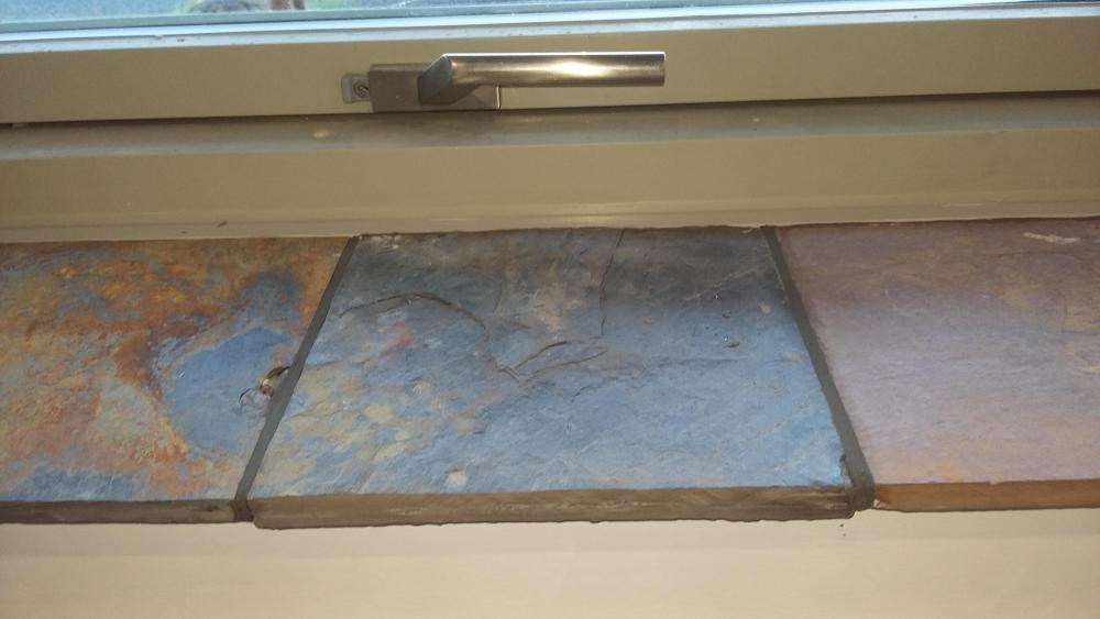
Grouting tiles is a job I hate. Whenever I have done it, I have always done it what I consider the "normal" way that is to fill the joint accepting some will get onto the face of the tile and you then have to clean that off. Not so bad with glazed tiles but a pain with stone. Today I was tiling the utility room window sill using up left over slate tiles from doing the floor. I only had a series of short gaps to grout. So why not mask them? I have never seen anyone suggesting the use of masking tape when grouting. It could be a bit tedious masking all the joints of a large area, but I thought I would try it: Apply the grout, wait for it to go off a bit, smooth the joint then before it is completely dry, peel off the masking tape. No scrubbing or removing grout from the face of the tiles. Has anyone else tried this? Why is it never mentioned by anyone?1 point
-
I'd have thought all that tea and biscuits would generate considerable lavatorial activity...0 points
-
Went to a cafe in Mousehole and there was a sign in the toilet. "The hands that clean this also make your food" I never went again and noticed it is closed down now.0 points
-
Not really much help but the pipe needed putting in before the beams went down, you could have ducted and concreted it to come up under the island so it was sealed. Always have to think 10 steps ahead.0 points
-
0 points


