Leaderboard


Popular Content
Showing content with the highest reputation on 10/07/23 in all areas
-
In my topic Modelling the "Chunk" Heating of a Passive Slab, I discussed how I used a heat flow model to predict how my MBC WarmSlab heated by UFH + Willis heater would perform. What I wanted to do in this post is to provide a “6 years on” retrospective of how the house and slab have performed as built based on actual data that I’ve logged during this period, and to provide some general conclusions. In this, I assumed 15 mm UFH pipework, but we actually used 16mm PEX-Al-PEX pipework with an internal diameter of ~13mm. At a nominal flow rate of 1 m/s, say, my three pipe loops in parallel have an aggregate flow rate of 0.4l/s or 1.4 m³/hr. At this flow, a 3kW (2.88 kW measured) heater will raise this stream temperature by 1.7 °C. However, when I commissioned the system, I found setting the Gunfoss manifold pump at a high setting (roughly equivalent to this flow rate) gave a very noticeable circulation noise in the adjacent toilet, so I tried the pump on its lower settings and found that the flow was almost inaudible on lowest one with in to return delta at the manifold still only about 5°C, so I stayed with this. The actual as measured delta for two loops of 4.9°C and the third slightly shorter loop of 4.1°C (close enough not to bother balancing the flows out). This corresponds to an actual flow nearer to 0.4 m/s or 0.56 m³/hr by volume. When scaled to adjust for this lower flow rate, the actual measured temperature profiles are pretty close to those modelled. I measured the actual Willis heater’s heat input as 2.88kW. In analysing the actual slab heating rates, I found that this raises the overall slab temperature by some 0.45 °C / hour after the initial start up. Plugging typical specific heat and density figures for the concrete, this is empirically equivalent to heating 25 tonne of concrete (Cmass = Ewillis/ΔT/SIconcrete = 2.88*3600/0.45/0.9 kg), or 10.6 m³ concrete by volume (23000/2400 m³). In the case where the Willis provides heating for the full 7 hour off-peak window (just over 20 kWh), at the end of this heating period the flow input to the slab is +9 °C above the initial slab temperature and the flow return is +4.4 °C. The temperature of the concrete immediately in contact with the pipe will follow this same gradient, with this temperature excess decaying radially away from the pipe centres. By the end of this heating window at the slab surface, there is barely a noticeable difference in the measured temperature of the floor above the out and return UFH pipe runs (perhaps 1°C). These temperatures and gradients are also comfortably within the reinforced concrete’s design parameters. As soon as the Willis is turned off, the internal temperature gradients start to flatten and any unevenness redistributed across the slab; the rebar reinforcing has a thermal conductivity 60 × that of concrete and this accelerates this, so that within an hour or so of the heating turning off, the overall slab is left about 3.1 °C warmer than at the heating start time (actually about 10% less than this, as the slab has already started to dump heat into airspace). In my original modelling topic, I mentioned that my passive slab has ~73m² of concrete 0.1m thick (~ 17½ tonne of concrete with another ~10 tonne of perimeter beams, cross bracing and steel rebar, with the UFH runs laid in 3 × ~100m long standard “doubled back” spirals (common to most UFH designs) on ~150mm centres and roughly 50 mm below the slab surface. (Actually only 75% of the slab is covered by the UFH runs, because of the need to avoid proximity to ring beams, partition walls, areas under fitted cupboard areas, etc..) Nonetheless, this empirical 25 tonne figure is still consistent with the total volumetric 27½ total estimate if we assume that the rebar is effective at spreading heat through the wider slab over this multiple hour timescale. In conclusion, based on this modelling and observation: First recall our context: our house is near passive in class with a lot of internal specific heat capacity. We only need about 1kW overall heater input in the coldest winter months to maintain overall heat balance, e.g. either by a resistive heater such as a Willis or an ASHP. IMO, there are two extreme approaches to house heating: (i) “agile” tracking of occupancy patterns so the living spaces are only heated when and where occupied; (ii) a 24×7 constant comfortable temperature everywhere within the living space. Our warm slab design is very much optimised for this second case, and our slab supplier did a good job in designing an UFH layout to match the slab characteristics to this The slab is covered in “doubled back” spirals with each loop using up a full 100m roll spaced on roughly 150 - 200 centres (and avoiding partition walls and cupboarded areas) so that each heats roughly 15 - 20 m² slab. In our case three loops were enough, and there was no advantage in trying to squeeze in a fourth. Our 3 loops will happily take up 3 kW heat input. Circulation speeds between ⅓ - 1 m/s seem to work well, with the only real difference being the slower the flow speed, the higher the delta between in and return temperatures. The slab does just as its trade name suggests: it can be treated as a huge low temperature thermal store, but because of its extremely high thermal inertia, one that is not rapidly responsive to heat input. In our case, a heat input of 3 kW input will only raise the slab temperature by 1°C over a couple of hours, and radiating 1kW will drop the slab by only 1°C over roughly six hours. In a true passive class house, one key to heating economy is the high level of thermal insulation coupled with a substantial internal heat capacity. Trying to drive such a house in an agile manner is a fruitless exercise, so forget the traditional having room-specific thermostat control; forget having traditional time-of-day heat profiles. It is far easier to treat all ground-floor rooms as a single thermal zone to be kept at a roughly constant temperature. In my view, using a resistive heating approach (such as a Wills heater) as well as an ASHP can both work well. In this second case something like the 5kW Panasonic Aquarea ASHP would be a good fit as it uses a modulated inverter compressor so it can heat the slab directly without needing a buffer tank. The choice is a trade-off between running costs vs. installation costs. In our case, switching from a Willis to this type of ASHP would save me about £600 p.a, in electricity cost, so I would really need to do the install for a net £ 3-4K to make the investment case feasible. However I would like to defer this discussion to a separate thread because there are other issues that such an approach would need to address.4 points
-
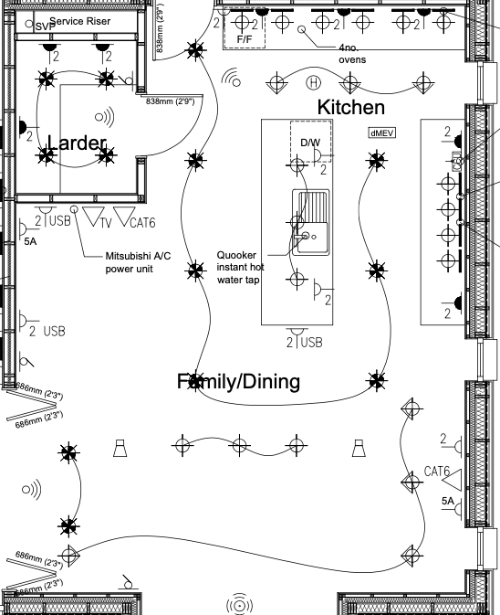
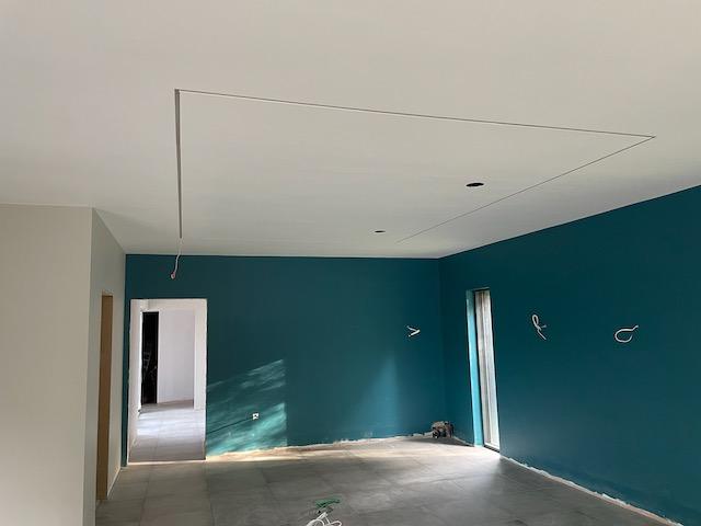
here's what we did after getting a design from a lighting designer. we will have 3 pendants over the dining table and island, directional spots to light artwork/walls etc, led strips under wall units and the walkway around the island we decided to swap out spots for an plastered in LED strip channel. we think it looks amazing and have planned for it to be equidistant from the island so it 'should' frame the island. here's a photo, kitchen is being delivered next week so we'll see if our planning worked out. so the only actual downlight spots we have will be the couple shown in the entrance to the kitchen/dining area. we really wanted to avoid that grid of spots look. you can be so much more creative and your layout for the room really lends itself to be so. using different lighting for each 'section' of the room will help the demarcation of each area and give different mood lighting for the activities that will be done in those areas. we feel that the £1500 we paid the lighting designer to give us a concept design for our house was invaluable. but we'll only know for sure once the house is finished and we're living in it.
 3 points
 -
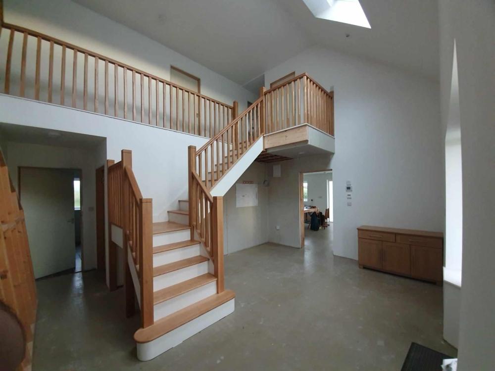
well after a year of notdoingverymuchreally this week marked a milestone- final stairs.
 3 points
 -
Oh we all have 20/20 hindsight,, at my age it’s called experience 🤣2 points
-
While I do use downlighters, but am not keen on using them in rows for general illumination - though I know many do. Though for a regular grid of downlighters, I do commend your restraint on the quantity selected which, subject to beam angle, could create some variation in light and shade. But it's not the way I'd do it. Personally I'd first be thinking of choosing lighting to suit the particular uses of the space - so lighting above the dining table and the kitchen island, to the sides of the sofas for reading / watching TV, and additional task lighting over the kitchen worktops. That could be a mixture of pendants, floor / table lamps and spots, for example. Then I'd be looking at highlighting any particular architectural features (including plinth lighting), or where any paintings or other features may go. Finally I'd be considering whether or not there are any particular gaps that may need additional illumination. Ideally, have at least 3 different layers of illumination, with dimmers on at least the principle layer. Other factors to consider are beam angles, light temperature and the colour rending index of the bulbs.2 points
-
This is a clever solution from @George for common domestic applications, very practical (and once you see why so obvious) and cost effective. You'll be surprised how cheaply you can buy loose bars and how easy they are to cut them on site yourself to supplement an A type mesh. For all here is a bit of an explanation and a bit of "but here is the catch" at times! An A type mesh has a bar spacing of 200mm each way. The table below is a good start to look at. "A" type meshes are usually used to control cracking in slabs, particularly the A142 and A193. These are "non structural mesh applications" which means that if your floor tiles crack then the building / floor will not fall down.. that keeps SE's awake at night if things could fall.. loss of life. Often we use A142 and A193 for small ground bearing slabs and slabs on insulation, sometimes these ground bearing slabs that have less (further apart) movement joints in them... the concrete shrinkage stresses are higher so we use a heavier mesh to give us more space between the crack control joints. Now often we can use say A252 and A393 meshes for say ICF floor slabs, walls and suspended floors. Here the mesh suddenly becomes part of a reinforced concrete member... it no longer is there to just control cracking but forms an integral part of a main structural component.. which is a structurally reinforced concrete member.. like a reinforced concrete beam over a big bifold door opening. Now the design codes require a minimum percentage area of steel reinforcement based on the cross section area of the concrete as this is now critical to safety.. won't fall down as opposed to cracking your floor tiles. This minimum percentage requirement often results is a big jump in the amount of reinforcement you need to use. Often you'll see on BH folk (the ICF world is a case in point) wondering why they have lots of steel mesh and bars specified for what looks like an innocuous slab that others seem to get away with. I hope the above explains that the two different animals. The B meshes are intended for reinforced concrete (structural members) so have closer and heavier bars in the span direction if spanning in one direction, the cross and smaller diameter bars work as crack control and to tie it all together.. so they are thinner and at larger (200mm )spacing. In the right application they are cost effective.. they would not make them if they were not. For all and on BH we want to keep things simple stupid and get stuff off the shelf. Most SE's designing self builds will / should take into account that we don't want to complicate concrete design and rebar as the more complicated the more it will cost on site.. introduce risk that things may not get built quite the way we hope. We will often design the reinforced concrete members simply.. technically over design but in the round most economic for you folks on BH once you take into account labour and material availability. Now if we were designing say a car park or multi story building with multiple continuous spanning reinforced concrete beams we use a technique called "moment re distribution" which means we appreciate the steel will stretch and when it does it sheds load to other parts that have spare capacity so we get more bang for our buck. Now an intrinsic difference between an A and B mesh is that the steel has a different amount of "stretchyness" called ductility. The above may have the info you did not hear which is why they don't want to swap out the more ductile B mesh for an A mesh. I suspect they may not have gone into that much detail.. so keep pushing and posting if you want some feedback.
 2 points
 -
Some level of competence and training is needed. I'd have to see more closely but I think this is surface staining from swarf, created by steel particles from cutting, and left on the surface. Cutting discs should never be used, but they are. That spreads a dust of iron filings all over and also overheats the steel and the edges will rust. Paraffin and elbow grease cleans thd surfaces. Damaged ends need painting. So you need sheet from a recognised supplier. Beware agricultural quality. Then it needs knowledge. A half decent builder can do cladding but needs to know about cutting. Or you hire the nibbler tool and make them use it.2 points
-
So in the last couple of months we've moved on quite a bit for us. We started on our next section of the build, to be the snug and entrance hall. This is the sticking out part of the 'L' of the build. We removed the roof covering some time ago, so at the start of July it looked like this. Then the 4 layers of floor and internal walls were broken down Then the walls came down and trenches were dug and filled up again Sometimes with building it looks like we do loads of work and then cover it all up again Once that was set, we started on the foundations and while we had access we had to build out the floor to the correct level for everything that needs to go in there. From the DPM we had to go down 650, almost as deep as the foundations at 750 While we were going down and starting to build the walls back, we had 100 ton of this. Crushed by this beast He was worried about our Suffolk Hill, aka a small slope as his machine is 24 ton and totally home made using his built in pecker for some of the tough concrete crusher.mp4 So, quite an active couple of months. Next is to build the floor in what will be our snug and hall, first hardcore with blinding sand layer (wackered down), then cellcore as we have some clay, then 2 layers of mesh and the concrete pour. The mesh and pour needs to be inspected by our BCO. Till next time Adios1 point
-
How about this type of kit? https://www.epicair.co.uk/collections/airflow-airflex-semi-rigid-ducting There are 75mm round and 115x51 oval ducts. They have ceiling and floor plenum outlets. We have the older version with metal plenums, you could wall mount them between studs and run 2x 75mm round (or use oval) to each one in a radial scheme. Or you could mount them through the floor (I think they have specific ones for that) It was a pretty easy system to use, just drag the pipe off the coil, cut to length and stick in socket. The radial scheme has more pipes, but they are smaller and you don't have to worry about sizing down as the run goes on or about inter room sound as much.1 point
-
1 point
-
Oh and use 50mm pipe1 point
-
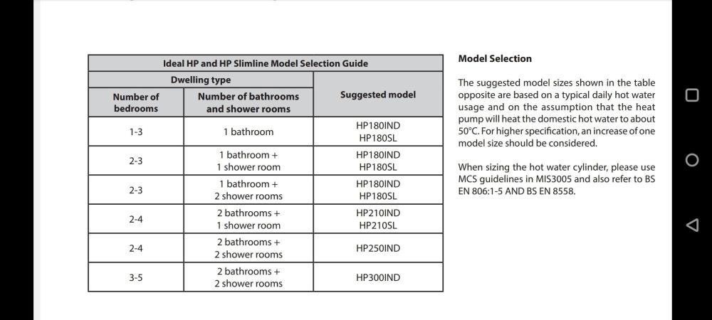
Look at specific heat pump cylinders, if it doesn't state the coil size move on. Ideal cylinders are made by Gledhill, but sold considerably cheaper. 3m2 coil Telford heat pump cylinder 3.3m2 coil. Sizing guide for heat pump cylinders
 1 point
 -
+1 Although a hole at mid height on the joist better than notching. Sorry if you know this but... I leave a clearance hole around the trap in the ply. I plumb the bottom of the trap in position in the floor and support it losely in the right place but with some freedom to move vertically (eg clearance hole nneeded around pipes to allow say 10mm movement vertically). Then fix down ply and tray. Immediately fit top part of trap through hole in tray into bottom part of the trap. This pulls the bottom part up to the under side of the tray hence the need to allow for some vertical movement. Do some dry runs with spacer to represent the mortar/tile adhesive.1 point
-
Get the thermal camera/ir thermometer and mark between the UFH and fix it down.1 point
-
Get a flat steel plate made to span a good length of the joist and it will let you make the cut out1 point
-
Can you rotate the tray 180? Failing that, get one with the waste in a different location.1 point
-
Get a cylinder with a heat pump coil about 3m2. And size the cylinder appropriately. All cylinders are pretty much equal, just capacity difference and coil sizes.1 point
-
If you are happy to work under the floor then go for it! Too claustrophobic for me (plus I'm over 6ft and tend towards solid than skinny). The Americans do use the dates with carpet. Usually several around the perimeter, especially under windows. They also (sometimes) have them in walls low down, you could come up from below inbetween some studs and then through the wall with a decorative grate... Though, if you were a fan of the X files you might not be too keen!
 1 point
 -
I think you’ll be surprised how ok it looks . Problem in offices is the ceiling tiles are usually bust / discoloured etc . You wait , you see …..1 point
-
They're the exact ones I ordered!1 point
-
4 of these (one in each corner) of every cabinet join https://www.screwfix.com/p/inter-screws-m4-x-10-pack/65152 perhaps a length of 3x2 screwed underneath along the front (behind where the feet will go) and one along the back underneath 🤷♂️.1 point
-
What matters is that water flows out. So check the running surface of it when installing, as well as the edges, from corners to drain.1 point
-
Not a bad plan. Drill a few holes in for quick access for bugs and water, and it will be gone in 2 years.1 point
-
Yes definitely, otherwise your worktops could come away from the wall, simple small L brackets from cupboard sides at the top to wall/timber before the worktops go on, just behind the cupboard back board (you need to screw slightly down hill over the back board , I can supply a CAD (crayon aided drawing) if you want 🤣1 point
-
Ah, if there's no other reason for the warranty I think you're probably just buying yourself a placebo. I just did a Google of "nhbc forum payout". It doesn't make very reassuring reading. Yup that would work practically. There's certainly advantages with sticking to locally used building methods but surely timber frame isn't considered unusual anywhere now? Good systems like MBC are excellent but some cheap ones are poor. Personally I would ditch NHBC and just ensure its build properly by a competent and conscientious builder. You'll have far more comeback in reality.1 point
-
Found what i was talking about. With this tool the fixing pulls tight without spinning and so there is no damage to the plasterboard. Then you remove the screw and use it for your radiator. Highly recommended
 1 point
 -
Our neighbour discharges a septic tank into the burn just the other side of our fence, and the MVHR inlet is on the wall facing that, but at least 10 metres away. On a completely still morning in summer it can get a bit pongy there and the smell can get drawn in. If I notice it, I turn off the mvhr until a bit of wind builds to clear the air. The only filters I have are the built in filters either side of the heat exchange core.1 point
-
Just the top will do, feet on the floor give three points of contact, as said above careful you can get washing machine/dishwasher under it.1 point
-
I didn’t have a warranty but when I HAD to sell got a retro one.1 point
-
Just be careful in relation to what you put on the wall. I usually use sticks of timber to stand units off the wall. The problem you have to avoid is chunky deep timbers in the wall may well prevent your washing machine going back far enough into your unit. Ie; they hit the timber that you have put on the wall.1 point
-
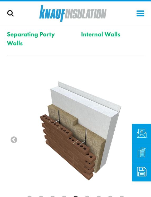
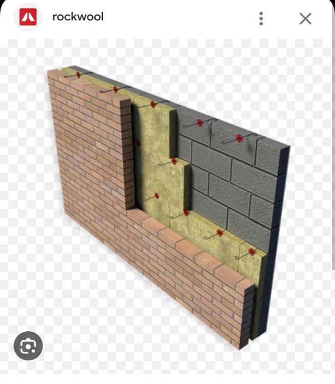
As if BG and Knauf don't know what they are doing? If this was me I would investigate further for some misunderstanding, and esp phone the suppliers.1 point
-
I did exactly that on our kitchen To give us a deeper worktop Fixed two layers of 3x2 inline with the top of the base units It also made the base units very easy to fit No drilling or plugs1 point
-
A new shower head may be easier. Glad you are on the mend.1 point
-
Knauf do a partial fill detail as do Rockwool. Personally I would always prefer to spend my energy making sure the job was done properly rather than spending money on a warranty that may or may not pay out later. Perhaps it's needed for the lender.
 1 point
 -
I'm also a vinegar user. Just don't leave it on too long / frequently as it can eventually affect the chrome.1 point
-
We live in the country, not too far from a large pig farm. On occasions with the wind in the wrong direction it can absolutely wreak outside. The smell has never made it indoors via the MVHR and we have no carbon filters. I’ve no idea why. Someone scientific may be able to explain? Also when it gets chilly out the wood fires start from the houses all around and that is also very obvious when outside but again the smell has never got indoors through the MVHR. It may not be the problem that you think it will be.1 point
-
All really depends on the house and the insulation levels and heating system. If it's very well insulated a thick screed or concrete may be best, a big chunk of concrete to slowly release heat, either drip fed in to floor or added in chunks on cheap rate. No need for zones or complex control, super simple. Retrofit a different story, UFH to free up wall space, not the best insulation, mixed in with a few radiators you may be better with system that takes heat and releases quickly. Horses for courses. No one solution fits all homes.1 point
-
Great blog.. keep it coming! Things I like are how your pics convey thousands of words. I can see the use of your simple and effective string lines. How you break out old concrete. Simple stuff that shows a found excavated and the different layers of soil. For all on BH.. if the sides of your founds don't look so clean cut as @LSB it's ok. Often in poor ground we want the sides rough so the edge of the concrete found gets an extra key into the ground!1 point
-
I second rear discharge, various fittings available to cope with mis alignment.1 point
-
I'd not fix into the external wall but use butterflies behind the plasterboard. Either the spring ones or those that open out when screwing BUT with the special tool like a rivet gun or it just spins around. I've had school toilet cubicles fixed with them. As below. Gripits look good but I haven't tried them.
 1 point
 -
I think that stagger will be fine. Not sure about the bog - waterfall - pond. I think it will be a muddy soup in no time. My brothers pond has issues just with leaf fall.1 point
-
Citric acid powder + water, cheap as chips. Not sure how careful you'd have to be with the shower head finish but works a treat in a kettle.1 point
-
Ha, I use vinegar and find it quite good (and cheap) Glad to hear this 👍1 point
-
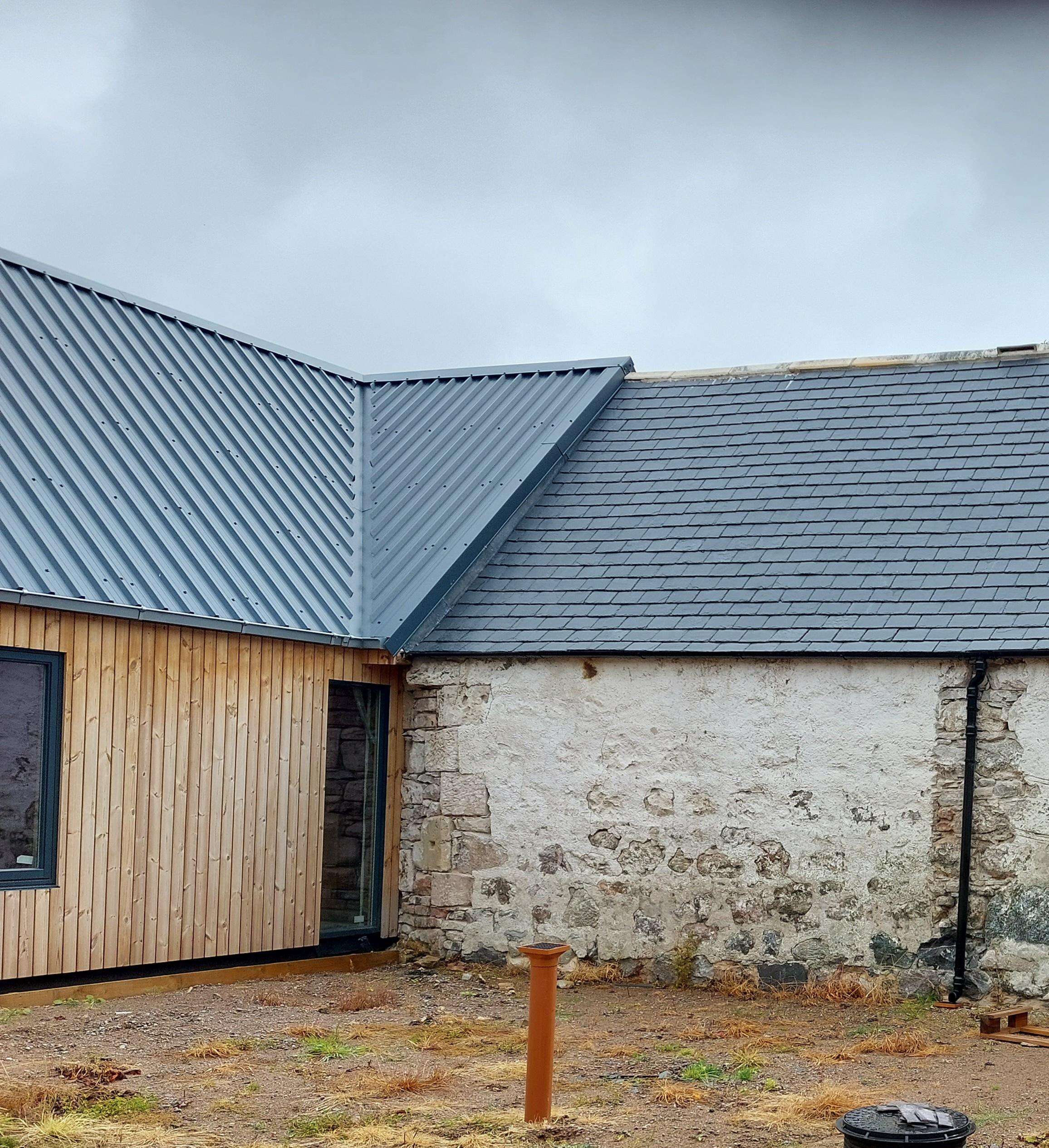
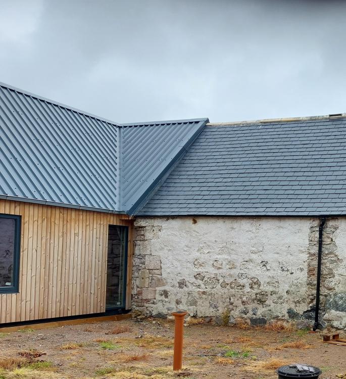
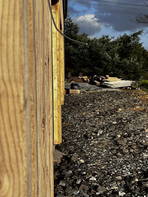
This is ours 9 months after cladding. It won't rust or have swarf on it. It was done by our joiner who would have used a grinder but was instructed not to and watched. The hire companies didn't stock nibblers which shows how little they are used. This wasn't intended to resemble a zinc roof. If it had, we would have used a wider pan. I think £40/m2 probably covers it. Re another current thread, that's a Lindab gutter on the new build and refurbished cast iron on the original.
 1 point
 -
It’s the little things. When we were setting everything out, which feels like a lifetime ago, we mulled over whether to set the garage and house perfectly in line or set the garage back. The debate was it either has to be bang on or the garage purposely set back enough so that it looks intentional as if it was marginally out it would long wrong. It took a bit of mocking up both structures to get it right. It’s spot on which always makes me smile because it’s only me (and the groundwork guy) that cared about it as we stood there in the rain and cold with a line and some timber.
 1 point
 -
Or most likely sequester into the soil. Partly how soil is made after all.1 point
-
Seems like a plan - I decided the kids were the bigger problem so I moved the dial on its spindle so it reads 5deg above the real value - not sure how much that has saved us over the years.0 points
-
I am happy, for £200/day + expenses, to come around and do some smoke tests.0 points