Beelbeebub
-
Posts
902 -
Joined
-
Last visited
-
Days Won
2
Beelbeebub's Achievements
Regular Member (4/5)
135
Reputation
-
Mimicking solar panels from an AC supply
Beelbeebub replied to Beelbeebub's topic in Photovoltaics (PV)
Roughly the area to fit panels is 2 chimneys 12m high x 4m wide. So if we assume I can get 10 x 2 panels per chimney we are talking 40 panels. Assume 450w panels so nominal 18kwp but with them being vertical and other practical limits maybe 14kw peak. So a fair split of about 1kw per flat maybe. Maybe each flat has a 3kw inverter and maybe 5kwh or 10kwh storage. -
Mimicking solar panels from an AC supply
Beelbeebub replied to Beelbeebub's topic in Photovoltaics (PV)
. Thanks for the solshare link. I've looked into it, and it is definitely a possibility. My two concerns are 1. It only does 15 flats per unit and I have 17! So two units or possibly 2 flats having their own standalone setup. 2. It seems quite "smart" and cloud enabled etc. I'm wary of stuff that requires a subscription - what happens if the company goes bust or is bought out and the new owner (or even the orginal owners) decide to jack up the prices or "enhance" your package by making it worse (hello Netflix)? Hence my wondering if there was a relatively simple sub £500 device that could allow for distribution of a single array between multiple flats via the already existing DC panel input. I was thinking of something along the lines of a current limiting 240v (or maybe 110v) power supply. The MPPT function would simply ramp up the current until it hit the limit which would be the maximum power point. If I wanted to reduce the power delivered to a given flat the current limit would reduce. The goal would be a system not reliant on external Internet connections etc. -
Mimicking solar panels from an AC supply
Beelbeebub replied to Beelbeebub's topic in Photovoltaics (PV)
So 17 flats in a 5 story building so the roof space is limited. The roof is also very old, very complex and not at all suitible for fitting PV to. The main option for panels is a pair of vertical arrays on the south side, where there are two large external chimney stacks - all the other vertical faces have windows, pipework etc on. There is also the matter of planning (aonb and conservation area) so it may be no panels are possible at all. Thereis alsoo two east facing balconies that could potentially have "balconysolar" style mounting on the balustrade . The problem is the flats near where the panels are don't need the EPC boost as much. It seems unfair to fit panels next to someone's flat and them not benefit from them, so I'd like to spread the benefits about a bit. Separate systems as mentioned by NickFromWales is a possibility but my worry is we could end up with a flat not using much of it's generating capacity, whilst the flat next door could use more capacity. Sort of like individual car ownership vs car pooling. A chunk of this depends on the upcoming EPC regs (due soon IIRC) currently (mains powered demand shifting) batteries are more or less ignored despite the potential impact on bills.It maybe fitting batteries gives me a big jump. Or not, who knows. At the mo I am just kicking about ideas. -
Mimicking solar panels from an AC supply
Beelbeebub replied to Beelbeebub's topic in Photovoltaics (PV)
Did that already but there is ultimately a limit to how long that can go on for as the running costs don't stop. The driving force is to get the EPC rating up. Reducing tenantt's utility bills is a nice side effect. -
Mimicking solar panels from an AC supply
Beelbeebub replied to Beelbeebub's topic in Photovoltaics (PV)
They all pay individually with whatever supplier they pick. I'm looking to provide some PV as a benefit, as you would new carpets or the like. It also helps with the EPC ratings. It might be that providing solar is the cheapest and easiest way to get a C (it used to be switching to gas) So the generated elec would be provided free and unmetered to reduce their bills. Obviously some days would be better than others and some usage patterns would be more cost effective than others but that's on the tenants. -
Mimicking solar panels from an AC supply
Beelbeebub replied to Beelbeebub's topic in Photovoltaics (PV)
I don't think supplying each flat with a submeter PV would work. The connection from the PV would have to be after their meter, otherwise I could supply elec and their energy supplier would get paid! 😁 But that would mean each flat would be interconnected after the meter. If flat A drew power it would flow through the meters of Flat A, B, C etc. There would be no way to untangle who used what. I could wire each flat to it's own string but then have to run DC to each flat, there there are issues of a particular panel fails that flat loses it's PV, whilst if I share across one big array I can just disconnect the affected string and the system runs at a reduced capacity Which is why I thought about distributing the PV power as DC through the solar input. It should isolate each system and prevent "cross feeding" and allow flexibility for each flat to use more than it's share if nobody else is using it. -
Mimicking solar panels from an AC supply
Beelbeebub replied to Beelbeebub's topic in Photovoltaics (PV)
I'm trying to work out a way for a number of flats to share a single panel array. My thinking is a single large array and 3ph inverter provide a 240v supply and then each flat can have a standard hybrid inverter and battery pack fed by what it thinks is it's own PV array, but is actually this hypothetical device taking power from the actual array supply (that is totally separated from the mains). -
Bit of an odd question : Is anybody aware of a device that takes an AC 240v input and outputs a DC supply in a manner so it can be plugged into a hybrid inverter and the inverter think it's connected to a PV string? Ideally the device would be able to be controlled so the power delivered to the inverter could be varied in real time.
-
Most newer inverters have an export limiter so you can run an 8kw inverter with a 4kw export limit. I believe you still need to fill in a form but there isn't an approval issue. The worst case is they limit you to the 3.7Kw "default".
-
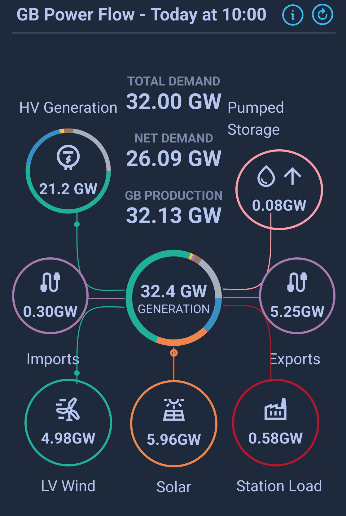
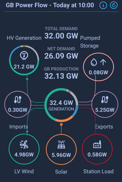
Saw this over on bluesky "Right now, mainland Britain has got almost enough wind and solar power to meet our electricity demand. Add in the power from nuclear and a small dash of gas (used solely to maintain enough mechanical inertia to stabilise the grid) and we are having to export 4.4GW to neighbouring countries. The need for that safety inertia will fall away with new renewable sites like Dogger Bank, whose inverters are capable of ‘grid forming’ as opposed to merely grid following… ... What this means is that their power electronics are designed to mimic the frequency and voltage stabilisation the the old spinning tire w turbines produce mechanically. Massive batteries being built around the country will do the same. That means that soon, on a day like this, we will see the grid run exclusively on renewables and nuclear." I did wonder about the various takes that we need fossil fuel generators for grid stability. Yes the spinning inertia helps stabilise the frequency but only so far as a spinning energy store will drop frequency as it delivers power. Once it slows down from 50hz to 48.8hz (or whatever the cutout is) it has to disconnect. So only a small portion of the power is available. Whereas inverter systems can theoretically provide 50hz for their entire power delivery.
-
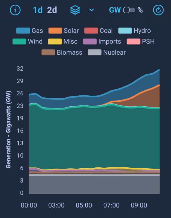
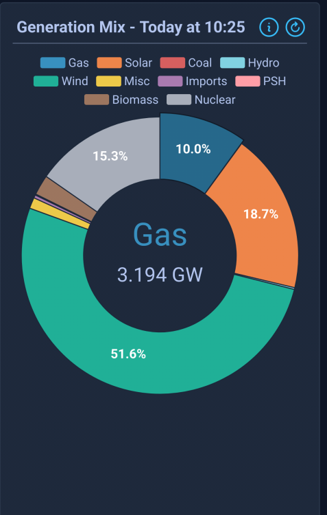
So this morning (Sunday 25 May) the wind is blowing, the sun is shining and nearly 70% of our electrifty is coming from renewables. But the wholesale price will be set by the 3GW of gas that is being produced. Fine, that's just how it is. But we are also currently exporting 5GW of electricity. So if we just exported 2GW we could burn no gas and get cheaper electricity? If you look at the generation mix graphs you can see that we seem to be constantly burning gas even though we have enough generation for demand (and even export). The gas portion holds at a steady 3GW-ish. I get we need to keep gas plants up and spinning even in periods of plentiful renewables just in case we get a fault or the wind unexpectedly dies or whatever and they have to step in rapidly. But in that case is the Dutch auction system really a good way to price electricity? Surely it wouod be better for gas plants to be in their own separate silo as a "backup" generator with costs spread equally across the year as with other infrastructure like substations and cables.
-
Spain/Portugal blackout
Beelbeebub replied to Beelbeebub's topic in General Alternative Energy Issues
I think the rise in gas later on is due to their model not "seeing" any more renewable generation being added in the future due to assumptions. From the notes on the graph you mention. "Natural gas generation responds to this increasing low carbon generation by falling rapidly until the late 2020s. It then stabilises as less new low carbon generation capacity comes online based only on EEP-ready policies. By 2040 it will be around 48 TWh, 61% lower than 2022 levels...." (my emphasis) The EPP-ready bit is that they only consider policies that have been approved or funded at the current time. So they aren't including any new capacity that is at too early stage of development. We don't know what the policies will be in 2040 or even the technologies available then. Maybe we'll all be whizzing about in our cold fusion powered jetpack by then. It is likely (in the absence of the aforementioned cold fusion jet packs or similar) that we will need some sort of thermal power backup and that may well be gas. But hopefully in smaller amounts than predicted there. -
Spain/Portugal blackout
Beelbeebub replied to Beelbeebub's topic in General Alternative Energy Issues
All good points about the possibility of local substation store The counter would be the tech for the home batt system is already here from multiple vendors There aren't any planning or space issues. The per house would be part funded by householders, probably the richer ones. The subsidy being maybe lower vat or some sort of rebate. That rebate could be scaled for companies or technologies we deem worthy eg UK manufactured systems or new chemistries like sodium thus giving an industrial benefit. The per house would give very good resilience against a Spain style blackout - plus alot will split "critical" circuits that are backed up (eg lights, freezers, comms) from non critical stuff like drivers or ev chargers to improve the runtime per stored kwh. This isn't easy for a substation system which woukd have to support people charging EVs, taking showers etc during a blackout. The per house would also make peak shifting /shaving more of an individual choice rather than enforced from above. -
Spain/Portugal blackout
Beelbeebub replied to Beelbeebub's topic in General Alternative Energy Issues
If lots of properties had 5 or 10kWh batteries with maybe a 3-5kW inverter then alot of the peaks could probably be ironed out. It would give a pretty good load shedding option for when something catastrophic happened to the grid eg a major inter connector going down. A 10kWh /55kW unit is pretty discreet these days and around about 5-7k installed. -
Spain/Portugal blackout
Beelbeebub replied to Beelbeebub's topic in General Alternative Energy Issues
The report projects gas falling by around 60% from current ie 10% total annual. As you say we will always need something for when wind and solar are a no go. In the absence of lots more nuclear it will likely be gas. But that's fine. What we do need to do is stop gas being the price setter outside of the times when it is doing the majority. Maybe if the price is set on gas (or whichever fuel) only if it exceeds a certain percentage. Essentially setting the price on the 90% (or whatever) generator not the 100% So the expensive gas etc get paid, but everyone else gets a lower (but still higher than cost) price.