Leaderboard


Popular Content
Showing content with the highest reputation on 06/18/23 in all areas
-
Window fitters are probably the least skilled that you will come across Plenty of foam and plenty of excuses When your measuring Do it twice Then cut a staff for each window Starting with the largest and working your way down As you say the fitting prices are crazy My wife and myself fitted 30 sash windows on our previous build in under two days and recently fitted three sets of sliders in an morning The heavy glass was the biggest challenge
 2 points
 -
I prefer a mastic joint there-we’ve all done them in mortar & a hairline crack is usually the result.2 points
-
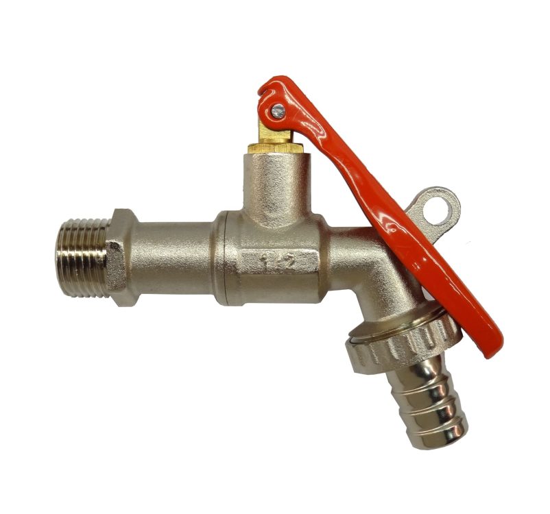
"Lockable lever taps" (search term) outdoors and a noddy combination code lock? I have these on the cold water outside taps because once upon a time nuisance kids and water meter.
 2 points
 -
You don't, you use a closed cell pipe insulation, such as armacell. 25mm wall thickness will give as good or better than pre made expensive stuff. Then use underground rated pipe or duct to keep it safe. Take you chosen pipe, I used Hep2O 28mm for my 6kW ASHP, add insulation, then insert through duct, I used twin wall 110mm black flexible duct. I made 2 assemblies one supply the other a return rack about 4m long each. I left a tail of Hep2O pipe out of each end to take up the wall and used a Tectite 90 deg coupler to transition to copper pipe through wall. Seal the end of the underground assembly with stainless mesh or aluminium scouring pads and closed cell spray foam to keep wildlife out. I spent about an hour or so making the 2 pipes.2 points
-
Day 31 of the build. (this is taken from the day we started shuttering the foundations) The weather up North has been spectacular for about 3 weeks, so we (Mandy and I) pushed to prepare and pour the slab before the weather changed, as I'm sure we will get a few weeks of low pressure, wet changeable weather after this spell. Following on from the foundation ICF walls, I'd already loaded around 20ton of 40mm to dust in a pile the slab area. Sat on the sand blinded radon barrier. Job one was to sort the drainage. I'd posted previously about my plan, and some constructive comments suggested changing my planned route, but with the extra length of run to the drain invert level I would have had to increase the floor height even more. So stuck with my original sketch. We ran string lines to mark the main areas, namely WC, SVP in the plant room, shower, WC and Bath, a need ran the drainage to the locations, as the utility backs onto the plant room I didn't add a drain in here as I'll run through the stud and use the SVP. Once the drainage was in place and is tested. We spread out the hardcore and compacted it. I used 10mm crush and run to bed the drainage and cover the pipes, I also ran ducting at this level, bringing in water, power, treatment plant feed plus some future ducts. To get the hardcore level / flat I used 3m lengths of galvanised conduit set on mortar pads all level to each other and used a 4M ally beam to screed the slab. I compacted the first layer then used another screed pass to fill in any deviations and used this as the level for insulation. I used a combination of 200 mm EPS 70 (50mm sheets and 100mm sheets all layed to stagger the joints, and used foam to seal to the ICF. The top layer was 100mm EPS150 this gives a firm hold for the UFH staples, and a firmer feel to the insulation layer. We plan to use a large shower tray and have this level with the floor, so I made this area sunken with two layers of EPS150 and a layer of 50mm PIR. As we were installing the insulation I installed 2 * 100mm ducts for the ASHP in the second layer of insulation these were only 800mm long, and a duct for cables. I also added flex ducts in the insulation for Hot & Cold services to the kitchen, utility, WC,Shower,bath, all these were cut using a hot knife. Lastly I cut some pipe for floor sensors in the kitchen, lounge, bedrooms and bathroom. The underfloor heating consists of three loops around 95M length, planned using Loop cad. The manifold was plumbed , filled and a pressure gauge to ensure no leaks. We have good water pressure so could pressurise to 6 Bar. ( With the heat ☀️ this rose to 9 bar one day). The above picture also shows K Steel screed rails. I used these to break the slab into smaller bays, and mainly will be under stud walls. The slab will for the foreseeable future be our finished floor, so I wanted to introduce expansion joints and force any cracking to these locations🤞. I also used Tibmix metallic dry shake topper on the concrete, the dry shake should help suppress the fibres and also increase the surface hardness. The pour happend on Friday 16th June, the first 5cube arriving at 8.30. we did the kitchen bay first which needed the 7t 360 to move / place the concrete, then, poured the WC / plant room and utility bay. This was an error, I wanted to pour the lounge next so both bays could be finished at the same time, but under the pressure of the pour took advice to do the awkward section next. This resulted in only a 3rd of the lounge bay having concrete, so this was spread out lower so the next load could fill the bay. By the time the second load arrived, the kitchen and utility bay was ready for power floating. The pan worked well and I had some time to start edging the slab, the rebar didn't allow the power float to get to the edge of the slab. By 13.00 all bays were in and leveled, but not floated, but the sun was very hot, and the kitchen bays was getting hard rapidly, I managed to float this but was struggling to to get a perfect finish. To dry shake makes the surface hard and this was apparent, the lounge and bedroom bays floated better, and to the main the dry shake suppressed a lot of the fibres but there are still some visible. The kitchen bay was rock hard by the time I managed to float again, and although it is fairly flat you can see, but not feel, the path of the power float. I used Setseal 6 as an acrylic sealer, which seals the surface and aids the curing process. By the time we finished the floor was rock hard, I mean hard, the idea being that the slab will slowly cure now but will not be affected by rain etc. Time will tell. Due to the temp, and the float not getting to the edge, I will have to carry out some remedial work on the edges of the slab, as by the time I go to troweling these it was too late. Today the slab looks great, it's flat and level, but the perimeter 2 inch will need some polishing, as will a section in the plant room. I'm confident I can get this fixed. Time will tell. The following picture doesn't do the slab surface any justice. It looks rough, but it's glass smooth. So 10.5 cube of fibre reinforced concrete. Power Floated, and this was non stop until 17.30. My chest and fore arms are wrecked from trying to tame the power float. I'm a little disappointed in the edge finish, but looking at it another way, it's way better than if it would have started raining, or the wind that we have today. I'm sure a few hours with a wet diamond polisher will rectify the edges. Maybe another hand would have been good. 🤔. Onwards to the ICF walls... .1 point
-
Trend door jig and hinge jig off Amazon. Set it up once and never change it, will make it dead easy to do and then re-sell on here .. There are imitation ones but the trend ones are the best1 point
-
Hire a plasterer then.1 point
-
If no shower door / screen, then be sure to fit hardwood door linings / architraves etc and paint them if so required. They all need to be sat into a fat bead of CT1 and then you'll not suffer any degradation of the timberwork.1 point
-
Where does the bed go?1 point
-
It is probably all down to visibility distance and the speed of the road. Just because there is an access there already, does not mean a new one will be approved if it does not meet the required visibility distance of a 40mph road. Of course if, before you applied for planning for the extension you changed the driveway to be using the existing dropped curb to the 40mph road, then you could refer to continuing to use the existing access to the 40mph road. that all depends of anybody notices if you have only just changed that.1 point
-
The door into the bedroom? Yes, any further up the wall and it will be hovering above the stair case1 point
-
yep. tiler is going to use the Impey water guard system on the floor and lipped up the wall (I believe) and then we talked about him painting the liquid tanking on the walls. he said liquid on the walls is belt and braces and I'm all for that so we're happy.1 point
-
Yes 2700 once the floor is in1 point
-
My big issue is having to make the dogleg through the walk in wardrobe to even get to the en-suite. I would have the door to the en-suite straight ahead as you enter the wardrobe from the bedroom, and then start planning the en-suite layout from there. It would probably be better moving the door from the bedroom to wardrobe to the right to align with the existing door into the en-suite.1 point
-
aren't they the really sappy b*ggers that aren't recommended in a stove?1 point
-
The cupboards in the wardrobe are too narrow to have rails for shirts and coats running parallel to the wall, would have to be perpendicular to the walls or use something like waterfall rails.1 point
-
At the end(s), yes, 100%. No need at all. These trays are the dachshunds danglers. Put 6mm ply under the tray, then lay the tray on top of that. Your tiler is spot-on, and you just wrap around the rest with more 6mm ply, glued and screwed at 100mm o/c's. Are you using the Impey (water-guard?) system eg the membrane to go wall to wall sides and ends?1 point
-
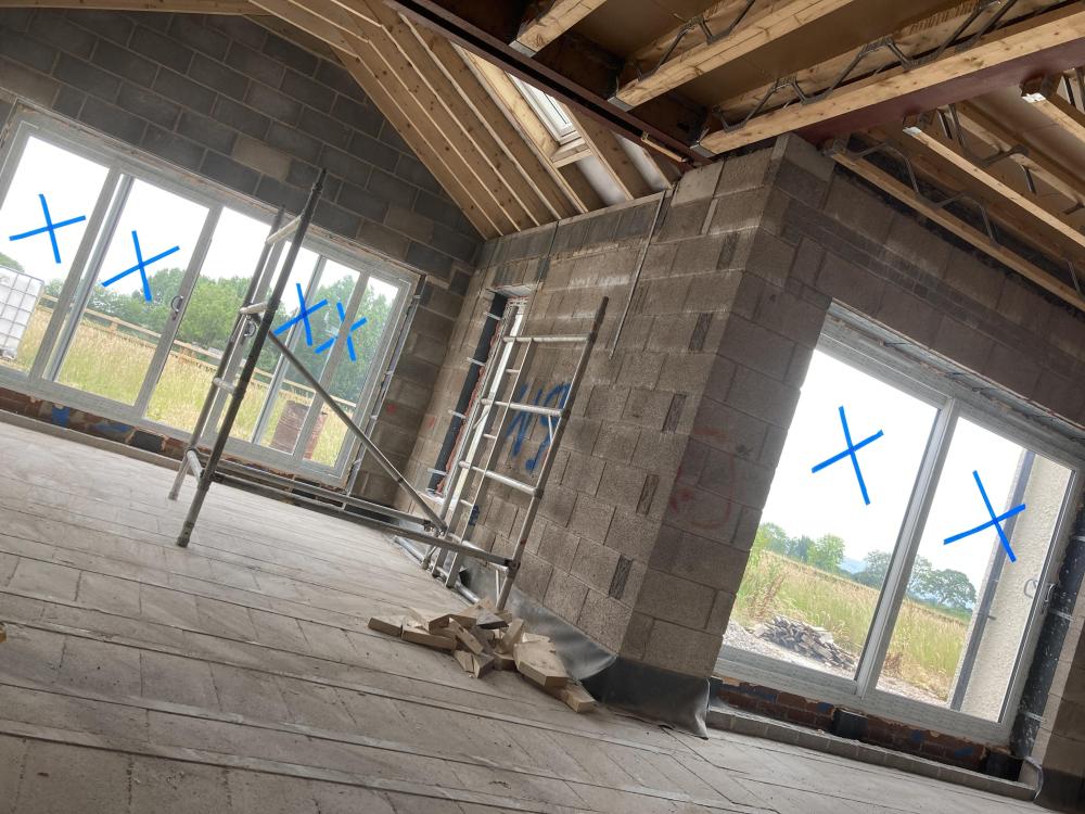
You use a 1 or 2 plank wide toe extension that gets you close enough to the wall. Then as they move down the lift the planks of so no splashes mark the new render.1 point
-
12 Harrier F1 butternut squash and 45 tongue of fire red runners. The trays from when SWMBO did her hanging baskets:1 point
-
I’d take it down myself1 point
-
Sitting on the toilet has your back to the entrance. Also from a practical view it becomes a pinch point the room, I would have sink and toilet on the same wall.1 point
-
I put a hole in a wall and nearly smashed a 2x2.6m window trying to move a few bits around. Don't do it. There are safer ways to save money.1 point
-
Unless they are very heavy tiles Dot and dab with moister boards and skim part way If they are heavy 10 mil plus S&C1 point
-
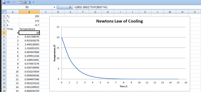
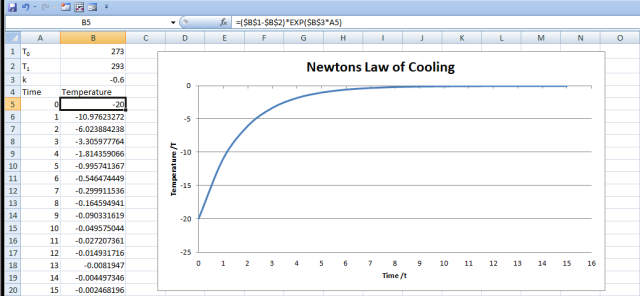
Because it is based on the Carnot Cycle. When a refrigerant gas is compressed it changes phase, from vapour to liquid (condensation) and when it is decompressed it changes back into a gas (vaporization). The heat capacity of the two phases is different. Taking water as an example (because it is also a refrigerant gas and you can test things at home), when in the liquid state it take 4.18 kJ.kg-1.K-1 to change temperature, when a gas it takes 1.86 kJ.kg-1.K-1 to change temperature. This may seem odd and you have to wonder where the extra energy goes when it is compressed, well it comes out as thermal energy. It is that thermal energy that is used to heat the building. There is a complication at the phase change temperature. At the exact temperature that water changes from vapour to liquid, or liquid to solid, energy is released, and oddly, a lot of energy. 2500 kJ.kg-1 in the case of water. It is a huge amount of energy and drives the global weather system. When a material is heated or cooled, it is not a linear process. but follow an exponential curve for both heating and cooling, with 'steps' at the phase change temperatures. Isaac Newton formulised this in the 1701. The formula for this is T = (T0-T1)e(-kt) There T is the final temperature after time, t. T0 and T1 are the initial starting temperature and the final temperature. k is the system propertied and is closely related to Ideal Gas Law and the physical restraints of the heat pump i.e. shape and surface area of the pipework. Knocking up a quick spreadsheet you get this. It is easy to see that the temperature drops very rapidly at first then tails off, taking longer and longer to cool. The reverse is the same when heating, except in reality energy is put into the compressor so I have adjusted the value of k to reflect this. Now to answer your question "Why are air-to-water heat pumps more efficient at lower water temperatures" It is down to where you are working on the chart. Knowing that the heating, or cooling, is very rapid when there is a larger temperature difference, and the compressor and air fans have to work harder to pass the fluids though the relevant heat exchangers, which are physical restraints on the system, and knowing that energy is just power multiplied by time, you can see that the same time is taken to raise, or lower, the final temperature by ever decreasing amounts. That is fairly simple, but in the real world, a heat pump is more complicated. There would be 4 temperature/time charts. Starting from outside and working inwards. 1: Outside air temperature and refrigerant temperature difference 2: Phase change within the refrigerant 3: Refrigerant to transfer fluid temperature difference 4: Transfer fluid to internal air temperature difference Throughout all those steps, there are different efficiencies, calculating them is our favourite pastime Solutions to Partial Differential Equations. Personally I prefer to call them Partial Solution to Differential Equations. It is for this very reason that collected data is used to create the CoP charts at varying temperatures and is often misleading when the underlying physics is not appreciated. There is also the problem what the Celsius temperature scale is used which highlights the phase transition in the outside air temperature and humidity changes, giving an unexplained drop in CoP between 4°C and 0°C (the frosting window) This usually shows up as a minima and is often misunderstood and thought of as a CoP of zero. Note: I used water as a refrigerant gas as you can play with this at home. You can put a litre of water in a pan, turn on the ring and monitor the time it takes to get to boiling. You can stop the experiment then and plot how long each K of temperature rise takes, giving you a heating curve. But for extra marks, you can leave it on the ring and see how long it takes for all the water to evaporate. The water will be at 373 K, but the time taken will be longer than you think. You can also do the reverse, but with kilogram of ice melting in a bucket of water, initially it will loose mass quickly, but slow as time goes on. It is because of this that the 'Ice Kings' could transfer Canadian ice to Barbados and store it in straw insulated building. It was the tail end of the chart that allowed it to stay frozen for months. In a heat pump, the cold side is between 250 and 260 K and as the ambient air gets closer to that temperature, the ability to heat the expanded gas diminishes, so the efficiency, with respect to time, is reduced. Again this is often simplified in manufacture's data to a difference in CoP between outside air temperature and delivered temperature, with a smaller difference increasing the CoP. Different refrigerant materials have different phase change temperatures, pressures and heat capacities, and what is used in Sweden for heating may not be ideal for cooling in Florida.
 1 point
 -
What sort of scaffold? Just plain poles with clamps at each join? Or a system scaffold like Kwikstage or cuplock?1 point
-
Nothing says you can't take the scaffold down yourself it's just all the risk is on your shoulders. If one of the bars hits the wall it's your fault. A scaffolder will drop it in no time compared to what you could do. Plus it's usually in the price. Don't try and save money on the plastering. Pay the money and get it done right as this is what you see everyday. It's a very skilled job. Good plaster can hide all sorts of sins left by brickies and joiners.1 point
-
This is not an answer but a complement to this question. When is the earliest, as in, the earliest in the *year* - how cool does one have to wait for the outside temperature to decrease for it to make sense to use a thermal camera?1 point
-
1 point
-
So we now know that this is a 150mm diameter combined drain (ie carrying both rainwater and sewage. And that in nextdoor's garden there should be a manhole cover The water company will have this same drawing, with additional info. Ask them for the full drawing, and btw isn't this sufficient to deal with their own question? Anyway you need the full drawing from them. It will have a table with all the drain and manhole cover levels1 point
-
The putty lime is a skim coat Use on All interiors Pre ear It’s like spreading cream and drys rather than sets So can be left in a mixing box and knocked up when needed1 point
-
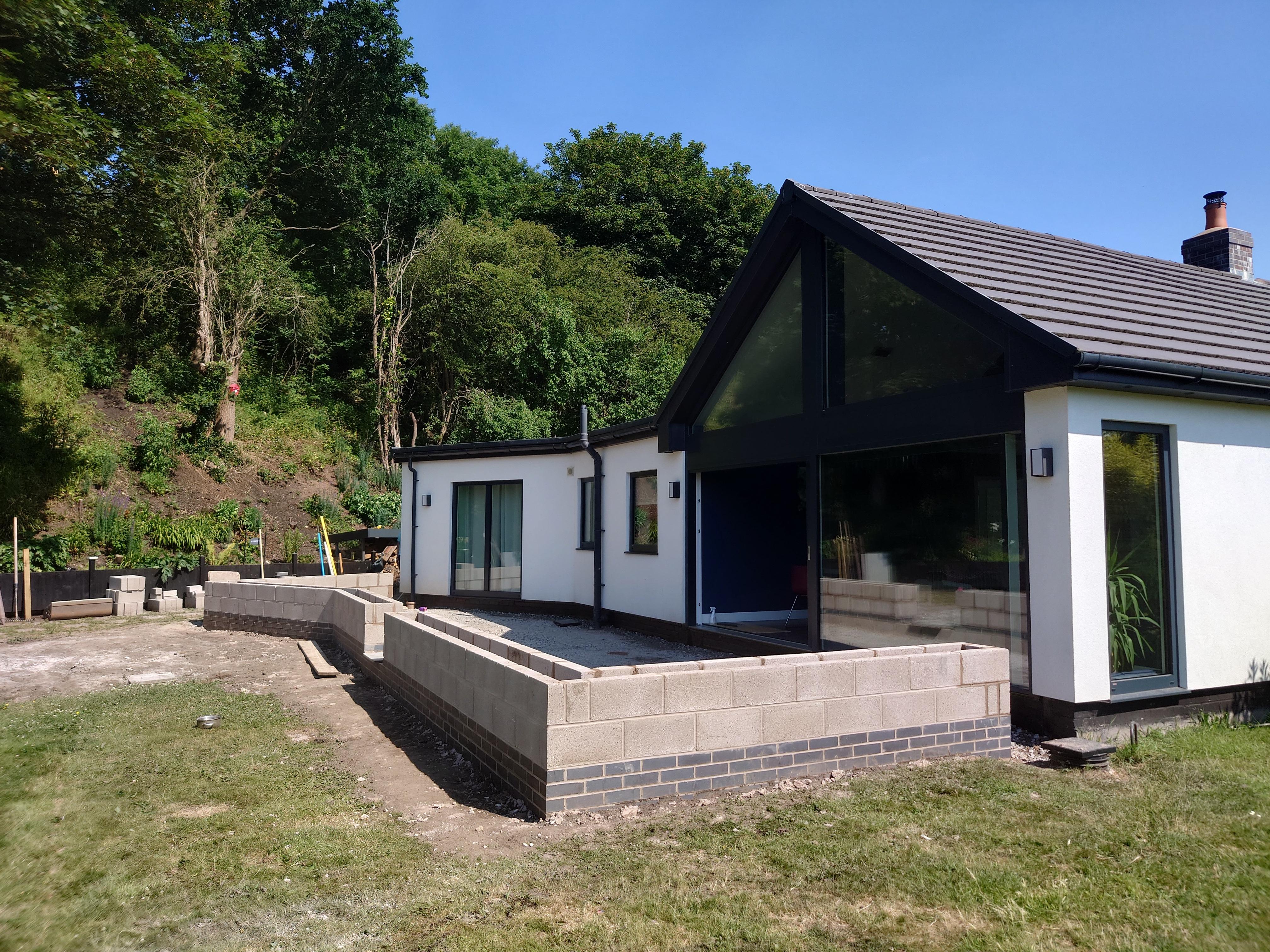
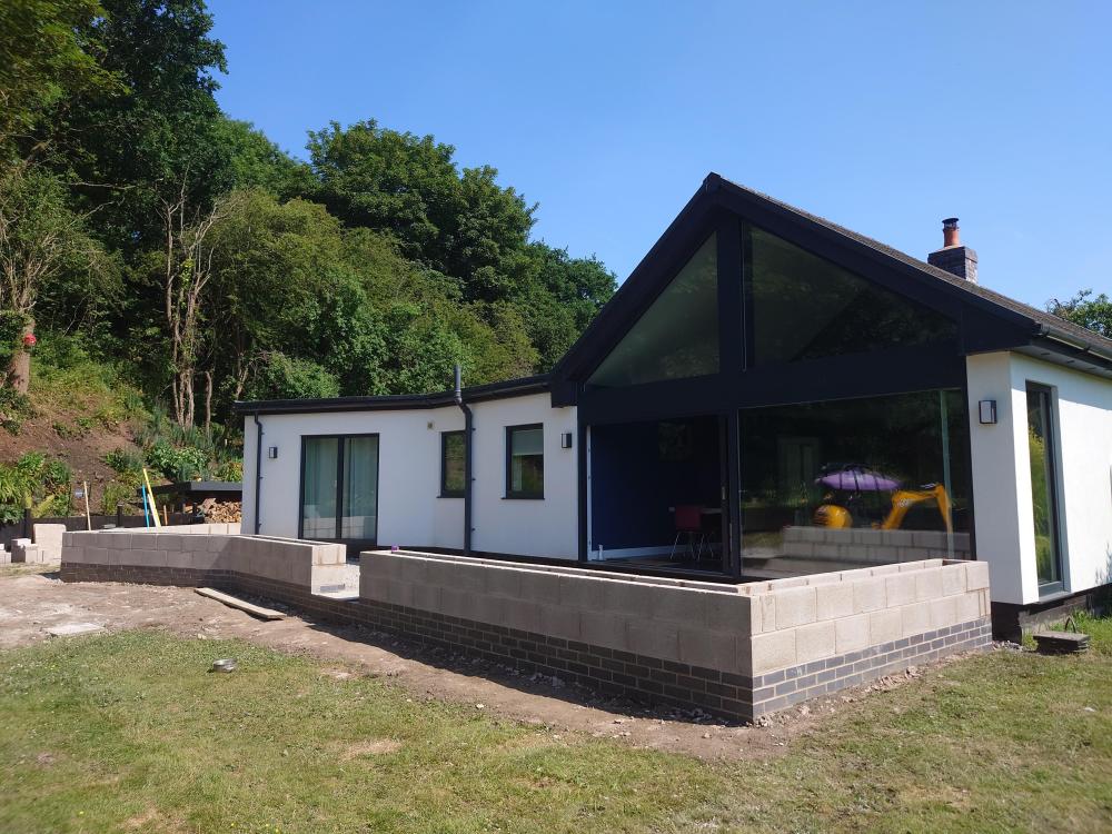
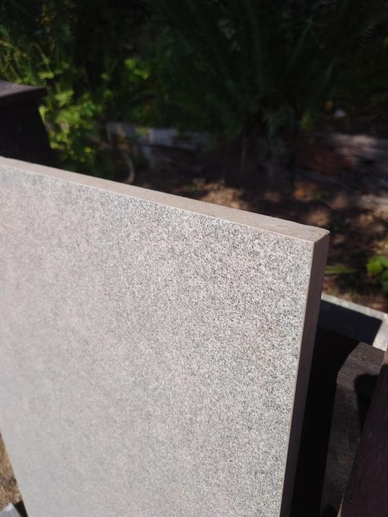
@S2D2 we haven't got the porcelain laid yet but it will be below the blue brick inside and the height will be 50cm from the bottom of the blue brick. Ground needs building up levelling outside planters and the white render will match the walls yet but here's some pics. We also sorted our porcelain. All 100m2 of it with 'a bit extra thrown in' for £2200 (we are having another patio area with gazebo). It's like a smooth almost granite like effect.


 1 point
 -
I just built my own. 2x lengths 110mm convoluted underground duct, left over from build, one length for supply the other for return. Closed cell 25mm thick pipe insulation, Hep2O barrier pipe inside and aluminium foiled on outside of insulation. End of duct sealed at both ends at ground level, with stainless steel mesh with closed cell expanding foam (to keep any rodents out).1 point
-
We are planning to use a Biorock due to its simplicity and lack of ongoing costs. I have spoken to a an engineer who works with very large sewerage systems and he only flagged the potential disposal of media whenever it will need replaced. The only ongoing maintenance is to check and wash the filter annually. I have read @Stones report on ebuild and hope his problems were due to poor installation and this will result in us (my builder!) being extra careful when installing the Biorock.1 point
-
What Declan says. We did that. We needed three plank ones though as we had to allow room for the ewi. Also known as Harp bars. Not to be confused with the Harp Bar in Belfast.0 points