Leaderboard
Popular Content
Showing content with the highest reputation on 05/10/23 in all areas
-
4 points
-
4 points
-
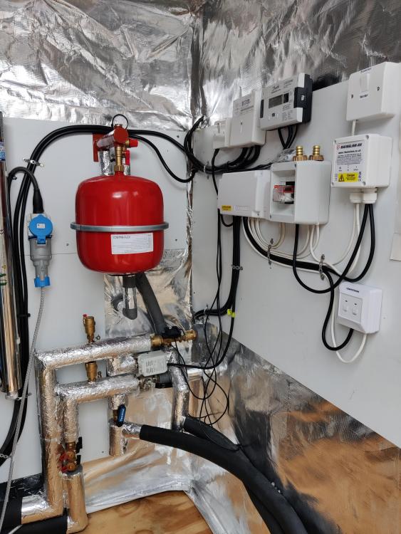
Inside water shed, expansion tank, 2 port actuator valve to summer house. Closed on a DHW heating demand and via a thermostat. The pipes also go to the house, underground, with 25mm insulation within 110mm double wall flex duct (one per pipe). The rest of the electrical stuff is 1. House wireless thermostat (x1) receiver, it switches the heat pump off if heating satisfied. 2. RF switch from from cylinder thermostat feeding 3. 3. DHW control relay, controls summer house 2 port valve and sends signal to heat pump for DHW heating 4. Summer house thermostat, opens and closes 2 port valve, if DHW is not calling for heat 5. Wiring centre 6. Electric meter for ASHP 7. Heat meter2 points
-
Your electricians has neutrals mixed up between circuits or a N-E fault. He should know how to test that, and should have done appropriate dead testing before energising. If he is scratching his head i would be starting to doubt his ability. The more I read of your post the less I trust him. Sorry. If in England or Wales I hope he is a member of a competent persons scheme as he will need to notify it under part P.2 points
-
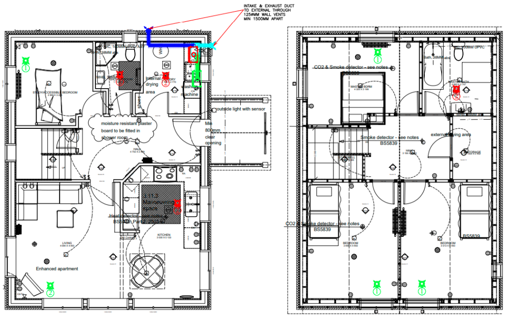
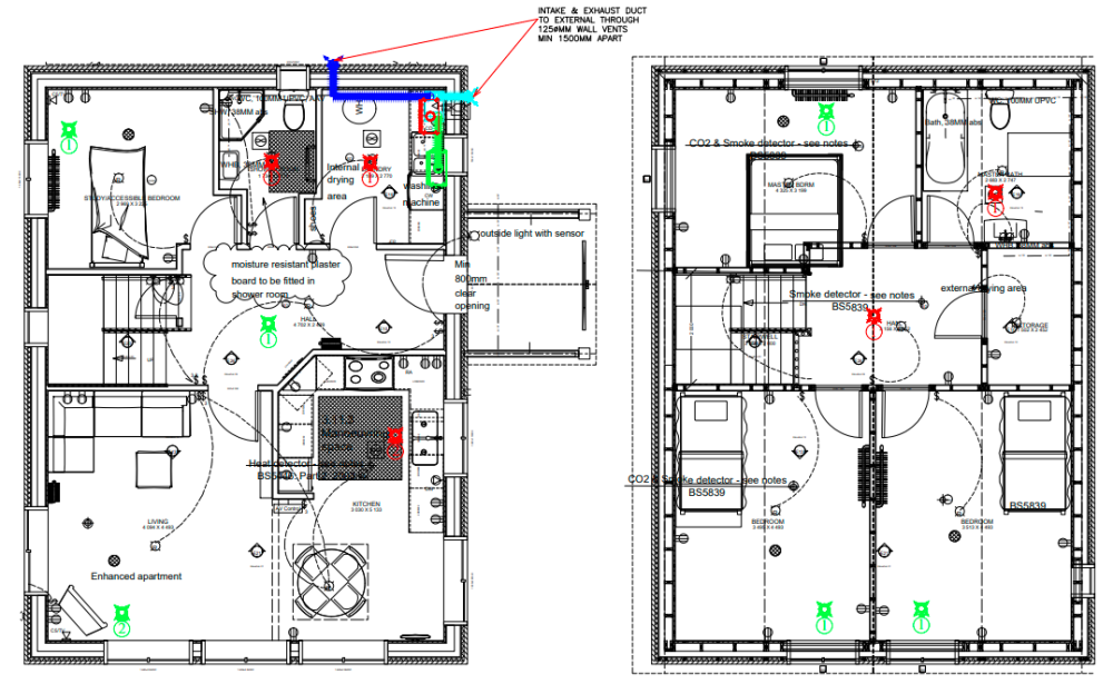
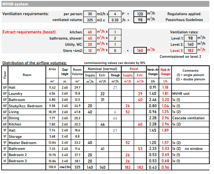
Any help/comments on the MVHR design greatly appreciated We have just ordered Zehnder Comfoair Q350, 90mm radial ducts, 160mm spiral and insulated ducts (split order: 80% BPC / 20% VentilationLand & phstore). MVHR unit will be located at the ground floor utility/laundry room. I received two quite different Location Guides from BPC. The first one was initially done for the 75mm radial ducting by an error but then no change in the guide when we pointed this out; the second one for the 90mm ducting after asking some additional questions regarding the number of double duct valves (in return they changed the design). Both guides show two separate exhaust/supply external terminals but this will be changed to Zehnder 160mm combo-grille (drilling openings vs building construction issues, plus wouldn't want the terminals on two different walls anyway). I also received some calculations from PAUL for the Zehnder unit and 90mm system, with the number of supply/extract points indicated in the table below (the quote was well out of our budget though so have not got the full design from them). Which one out of the three would you describe as the most suited? Can any obvious errors be seen in the valves placement, folks? 1. BPC Ground floor (left hand side drawing) has red extract points in 2x utility, 2x shower room, 2x kitchen; green supply points in 2x living area (dining area via cascade effect?), 1x bed/study Upper floor extracts: 2x bathroom, 1x in each bedroom 2. BPC re-designed Ground floor: extracts - 1x utility, 1x shower room, 2x kitchen; supply valves - 2x living area, 1x bed/study, 1x hallway Upper floor: extracts - 1x bathroom, 1x hallway; supply valves - 1x in each bedroom 3. PAUL calcs for 90mm ducting system and a different approach to the valves' number/ location (see the right hand side column for this) - no valves in the hallways at all, 2x extract valves in the upper (main) bathroom, and 2x supply point in the "master" bedroom (although it is slightly smaller in area than the other two upper floor bedrooms and much closer to the unit).1 point
-
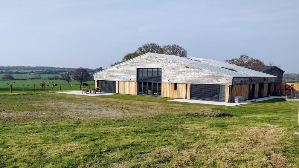
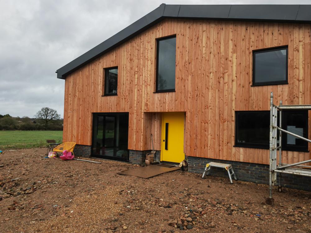
Hi everyone I just wanted to introduce myself. My family and I are just coming to the end of a self-build steel framed barn conversion which started back in 2019. We only have minor things left to do. I project managed and also designed the entire house and my wife and I did all the planning application. I'm not an architect - it was more the fact we were left in the lurch by a really poor planning consultant/architect that we decided to take over ourselves and pleased we did. Our house is fairly standard block and brick masonry cavity-wall construction and we have quite large 150mm block cavities (concrete blocks for the external skin and thermalites on internal skin) full-filled with 150mm breathable mineral wool insulation, plus a further 50mm waterproof mineral wool externally behind cladding (crucially still allowing plenty of ventilation behind cladding), 100mm PIR celotex in floor (would have done more in floor but we're limited by potentially low ceiling heights), 200mm PIR celotex warm roof with an airtight VCL. We had a builder build our foundations and shell and he also put up some plasterboard on internal walls, we have a full wet plaster on all external walls. We had a separate roofing company do our metal roof, a cladding company have done our larch cladding and electrician and plumber are close to finishing our second fix items. My wife and I took over from the builder after he left. I then spent many weeks applying a cement lime "parge" coat on the inner face of all external walls (prior to our plasterer doing the full wet plaster), and I applied air tight tape everywhere in an attempt to make the house as airtight as possible - it was hard because our builder did not see the importance of air tightness. I've also built an exposed brick wall spanning half the entire downstairs and we also fully prepared the entire groundfloor for our concrete pour - doing the insulation, membrane and steel mesh etc, as well as doing some of the insulation and VCL in the warm roof. We had a concrete company pour and powerfloat the concrete slab which acts as our finished floor surface, as well as being a good thermal mass. Our house is heated solely by an 8.5kW ASHP and costs very little to run, which does all our hot water and our space heating, via wet underfloor heating in our concrete slab on the ground floor (no heating upstairs aside from a couple of electric towel rails). We also have solar thermal tubes which isn't doing much at the moment with the cloudy rainy weather and we also have 7.6kW solar PV on our roof which will be connected to an inverter and batteries later in the year. We also have MVHR. We just had our air tightness test done and we scored 2.5 m³/hr.m² @50Pa for the standard air permeability air tightness test, and 1.96 ach/hr @50Pa under a passivehaus air tightness test (although I can't use the Passivehaus test result for my SAP calcs). Dealing with non-straight original timber roof perlins and other characteristics in the original barn, and being masonry construction meant getting it air tight was a challenge.. plus it was a bit of a battle dealing with most of the trades who did not understand the importance of air tightness - our main builder thought we would never be able to open our windows! And it was solely me doing any kind of air tightness work. I'm not sure if 2.5 for a masonry house is ok or not?? I had hoped it might be slightly better after all the time I spent but I'm glad it is lower than 3 though because we have an MVHR and these work better at 3 or below (and at the end of the day it is just a number). House appears to stay warm, costs virtually nothing to run, no mould or condensation thanks to the MVHR which also evenly distributes the warmer air downstairs to all rooms upstairs, so overall really happy. It's been a lot of extremely hard work, especially with three quite young daughters, and working full time. Sorry for the long introduction. Attached is a pic. Matt1 point
-
He did have a large tester around his neck with some prongs and I've seen him using those. No idea what they are. Look more like an expensive multimeter thing rather than one of those Megha testers I've seen on some YouTube videos.1 point
-
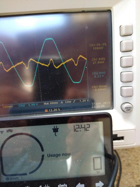
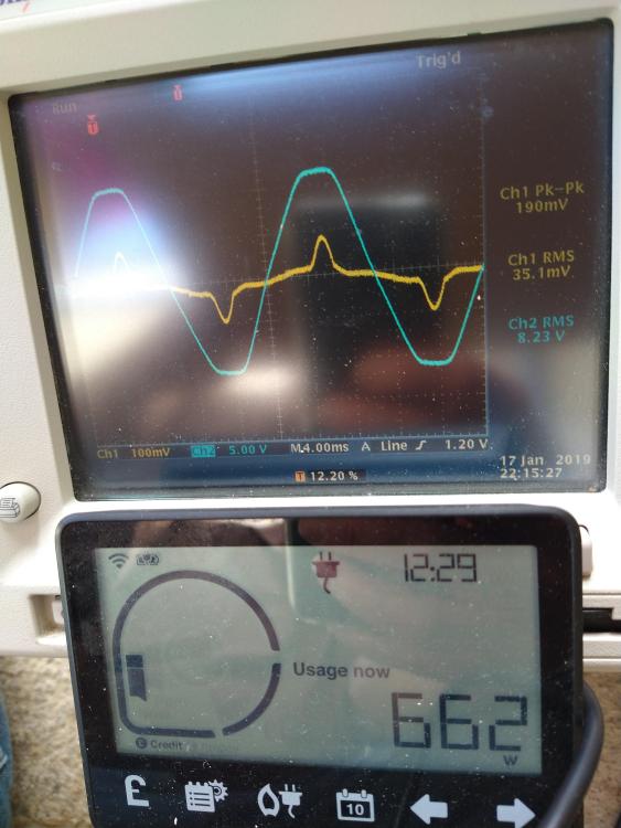
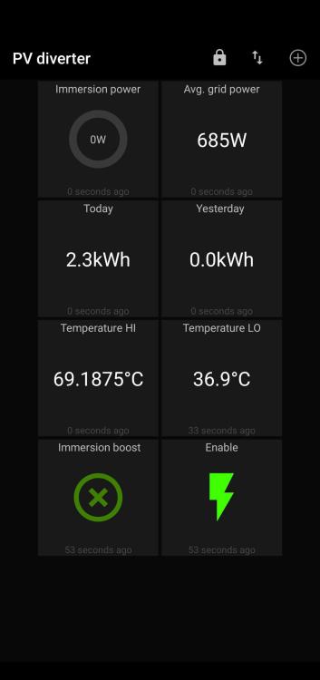
Always feels a bit pretentious starting a thread in Boffin's corner but I guess it's best to keep electronics & coding out of the other sub forums. Anyhow, I'm messing around with a bit of an 'old chestnut' - a device that spots power being exported to the National Grid and intervenes to dump it into something more useful such as a DHW cylinder immersion heater. Being tight, and having a comprehensive store of electronics parts to hand, I feel compelled to roll my own - as has been done by numerous others before me - such as Robin Emley and, I believe, our own @ProDave So far all I have is a small mains transformer, a couple of CT's and a scope looking at what happens when a grid-tied inverter pushes more into the grid than is coming out and I'm already seeing issues. First photo shows relation between voltage and current during base-load 662W import: The voltage waveform (blue) is typical of a small 240VAC transformer saturating (not the ideal way to represent the mains waveform but hey, it's safe). The current waveform (yellow) is 'peaky' in the middle of the cycle showing just how much of my ~700W baseload is capacitive - i.e. lots of switch-mode PSU's rectifying the AC and recharging their reservoir capacitors after partial discharge between cycles. So far so good I guess although I don't like the idea of sampling the distorted voltage waveform. Next photo is when the Sun comes out: Oops, 0 Watts imported, who knows how many exported then? That's my task here now. So the current due to the resistive component of the baseload is starting out from the zero crossing and immediately being cancelled out by the inverter which manages to push the current drawn into negative territory, until it gets overwhelmed by the capacitive loading later in the cycle. The inverter loses the fight near the middle of the cycle and current begins to flow back in from the grid. But on balance, over the whole cycle, more current was going out than coming in hence the utilities smart meter shows zero (it doesn't show export amount but the meter logs it in one of its registers - 1.1kWh so far!). The scheme seems to be to measure the real power, retaining its sign, on every cycle and keeping a running total such that when it reaches a certain (-ve) threshold (before 3600 Joules is reached) it triggers the Immersion heater to 'claw back' the same amount of Joules to keep from tipping the meter into registering an export. Thus filling and emptying a so called 'energy bucket'. Makes sense. But a few questions arise - how quick does the triggering of the Immersion load have to be? Can it be made less critical by setting a lower threshold? I ask because I can't easily wire directly from the meter area to the immersion so I guess a wireless solution is required and these all have a degree of latency. What are the other significant challenges I wonder?1 point
-
Might be a bit less than straightforward. I suspect that it also has a SB3 Magnetic clutch/brake The rating label shows SB3 and G100 which I think refers to Gear Motor. Can't seem to google up any wiring diagrams.1 point
-
I wanted something that could power the house in a power cut. Tesla Powerwalls had stupid lead times and so I went for a Luxpower Squirrel Pod with HanchuEss Greenlinx batteries the maximum 13A in a power cut is a little limiting but I’m planning to ask the sparky to wire lights and a coupling of emergency sockets to the EPS. but you’ll find that answer to your question depends on who you’re asking! If you read the threads in the battery forum you’ll get a good understanding of the sort of response you’ll get. 😉1 point
-
1 point
-
1 point
-
We have buildings reg sign off so the drawings are pretty detailed and (I think) our architect was very good and has given lots of details around specifications. We don’t have electrical plans and a few other bits which have been excluded from the quote. Now I think about it this probably makes it easier to compare. I’ve been very honest with all three builders and I like them all. So it will be difficult to decide if all quotes are similar! One thing we are particular on is having a very good brickie, so would like to see some of their previous work. I’ve not asked that yet though. I’m keen to waste the least amount of their time as possible.1 point
-
1 point
-
Hi Pete We are on a raft foundation. I'm not a builder nor architect but was heavily involved in the build getting my hands dirty when I could (sometimes even correcting things I wasn't happy with that the builders had done). We are a masonry build so it might be slightly different to your SIP structure I'm not sure..possibly not. Our raft foundation, from memory, was basically hardcore, crush, sand and then membrane and mesh etc then the structural concrete slab. The house was then built up around this and when water tight with internal walls done we then prepared for our concrete "finished" floor, designed to be at least 100mm thick but in some areas definitely 150mm. Thicker is better as it is less prone to cracking and actually also becomes a better thermal mass. Concrete, I believe (I might be wrong), is a better thermal mass than screed, but on the flip side takes longer to heat up than screed but then holds on to that heat for a lot longer. The build up of our "finished" concrete slab was all done by myself and my wife (as builders had left by this point) and we first made sure the structural concrete slab was all level (used some levelling compound where we needed it, and then laid our PIR insulation (celotex) directly on top of this. Then taped it all up (very important as concrete mustn't get through the gaps otherwise the insulation boards could float - this must always be done whether you are using concrete or screed on the top of insulation). Above the taped up insulation boards we then laid the thick gauge black damp proof membrane, taped up where any joints were in the membrane, and taped up against the walls. And above the membrane my plumber laid the underfloor heating pipes. And above the UFH my wife and I spent a couple of days laying "meshmen" (which are supports to hold up steel mesh) and laid steel mesh, all tied together. And then it was ready for the concrete pour which would act as our finished floor surface - and the same company who did the pour also did the powerfloating, on the same day, literally about two hours after the pour. In hindsight I would have preferred to have had the insulation and UFH all in the first layer of concrete slab, ie. the structural slab right at the beginning of the build, as it would have allowed a lot more ceiling height and saved the cost of the second concrete slab. Apparently a lot of passive houses work like this and have just one concrete slab which acts as both the structural slab and also the finished floor slab with all the insulation and UFH in it. In regards to the UFH not working in 150mm thick concrete.. it definitely does work but it works differently to what people might expect such as it might with thinner 75mm screed. It doesn't feel warm to the touch - but it equally doesn't feel like cold concrete either. Our pantry which has no UFH in it was very cold to the touch, in the winter, compared to the rest of our open plan area which did have UFH on. It definitely emits heat as when you look at the thermostats the temperature rises (it does take about 12 to 24 hours to change temperature as an ASHP works much slower) or when you walk in from the outside the heat really hits you. And it also retains heat very well even without any heating on. During the build before the UFH was operational the house was so warm. We love it. The concrete can still get warm to the touch if you raise the flow temperature up on the ASHP. But you really don't need to raise the flow temperature up at all as a steady low flow temperature is all the house needs to stay warm. We have ours at the lowest flow temperature setting of 25°. We haven't had the UFH heating on for the last three months as the house has stayed so warm on its own. The ASHP also runs much cheaper when you have a low flow temperature and have it on all the time too (seems counter productive but it works much better that way - and have all the UFH zones on too). The concrete slab works really well with the ASHP and UFH as it retains and emits the heat really gradually, instead of one big blast - allows it to run really efficiently. Especially so if your house is reasonably air tight too and has an MVHR. Hope this helps. Good luck in your build! Let us know how you get on.1 point
-
No, a section 73 application is to either vary a condition or have it removed. Instead you'll be applying to discharge the condition, i.e demonstrate that you have complied with what the permission required you to do. A different animal. So it'll be pictures of the material being used, manufacturers literature, colours and in the case of the windows and roof lights, cross section details (probably available from the manufacturers website). Obtain samples if need be. Submit your application with the fee. Get a reference for the application and add that to any physical samples and drop them off (Council's don't seem so keen as they used to about physical samples). Remember, if you have other pre-commencement conditions to discharge, then do them all at once as there is a fee per application but you can lump several conditions into one discharge application. They are obviously not keen on uPVC so it's something else for the windows!1 point
-
They don’t need to be that specific. They just need to highlight the risks. They talk about the different approaches to building with some of the pros and cons of each so could easily cover it generically. They also have financial advice available so it’s something that may be covered there of course. Self-building is a risky venture even if you don’t have a company going bust on you.1 point
-
I worked on various projects over the years involving mains replacement, new meter connections. I'm 99% sure there will be a 25mm MDPE tail coming off that meter box and connect to your private supply within about 500-1000mm of the box.1 point
-
Oh dear that does not sound encouraging. I am all in favour of recommending upgrades where they are necessary but it seems a lot just want to bang in a new consumer unit regardless.1 point
-
I'd avoid branches in 4mm as terminating is a pain and you want to avoid junctions Have you calculated the expected load for each circuit? I'd be surprised if most couldn't be handled on a 20 amp or 16 amp radial in 2.5mm - A 32amp 4mm circuit would be circa 7kw.1 point
-
The advantage is in its longevity. There are lead roofs, still keeping the rain out, that were installed before GRP and EPDM was invented!1 point
-
1 point
-
ideally id put the TMV at the aquarium end so i can easily manipulate it but its a good shout. I did plan on doing that originally as i made the 2 feeds with the 2 NRVs but in the end i just stuck an elbow on in with some pipe to mix it. Not sure why, think i lost interest in the job but i already had the 2 NRVs in place ready which seems mental to sack it off right at the end. When i re-jig this i'll use the TMV and rebuild to just have the one NRV and lose all the copper as its meant to be bad for the fish and shrimps but ive had no problems there since i put it in. What i do is use a speedfit connection and then have a removal cleaning "wand" that is basically some hose clipped to a small length of 15mm pipe with an end on to stop the fish ploughing down the hose and into the soakaway, then i just remove it from the speedfit fitting when ive cleaned it. The syphon works class and its incredibly easy to drain and fill the thing up, which is a horrendous job when the tank is in the front room.1 point
-
Just an aside, but you’ll need to fit double check non return valves onto the hot and cold feeds to the fish tank if you’re back-flowing dirty tank water through pipes; which are connected to the potable water system. There’s a high risk of back-contamination of your drinking aka potable water system from doing this. The NRV’s need to be 1x hot and 1x cold, on each of the individual supply lines to the tank. Or, combine the feeds at the manifold into a TMV, and fit a s1x DOUBLE check valve on the output of the TMV.1 point
-
+1 minimise all joints that's the whole purpose of the manifold.1 point
-
Forgot to say it will prevent the natural weathering of oak if that's what your looking for.1 point
-
Osmo uv protection oil clear. Good stuff and will keep the look of oak without darkening it.1 point
-
Oily massage always works for me. Don't matter if I am grubby or no.1 point
-
1 point
-
1 point
-
Joint at the manifold so any potential leak is above floor level1 point
-
Because its ground in with sweat and hard work.1 point
-
Thank you for your response @Johnny Jekyll I have inquired this and got an email from BPC explaining that the vales in the hallway would let them balance the machine. They also like to have an extract in the upstairs hall for heat grab. (As heat rises, there is usually a good source of heat there.) I really don't know. My another guess was, they added the supply valve in the downstairs hallway, to allow more air in the living room? The location of the living area supply valve would perhaps cause the fresh air making a shortcut to the kitchen extract point, creating a stale air zone when the sitting area is?1 point
-
As a member mentioned below, not if it’s a bungalow. Could also already be a 3-storey town house. The OP doesn’t state what the existing house is yet.1 point
-
One option is just to let it weather to a nice silver colour - as long as there are no significant areas that receive regular water splash and remain constantly damp. You then end up with a nearly no-paint / no-maintenance finish. If you look at Elizabethan houses you'll find that the old untreated oak has gone nearly black and crazy hard. That's the beauty of oak.1 point
-
Yes they do Whilst there will be increases or in some cases decreases to offset Your eventual choice will have to be quite specific on what they are charging for Breaking things down will take longer but protect you both1 point
-
Yes, it can substitute, if fully bedded into flexible tile adhesive and screwed at the edges etc, but I would still ply it. Nothing worse than fitting out the entire room to then slowly see cracks in grout and then tiles coming loose. Major works to put that right retrospectively.1 point
-
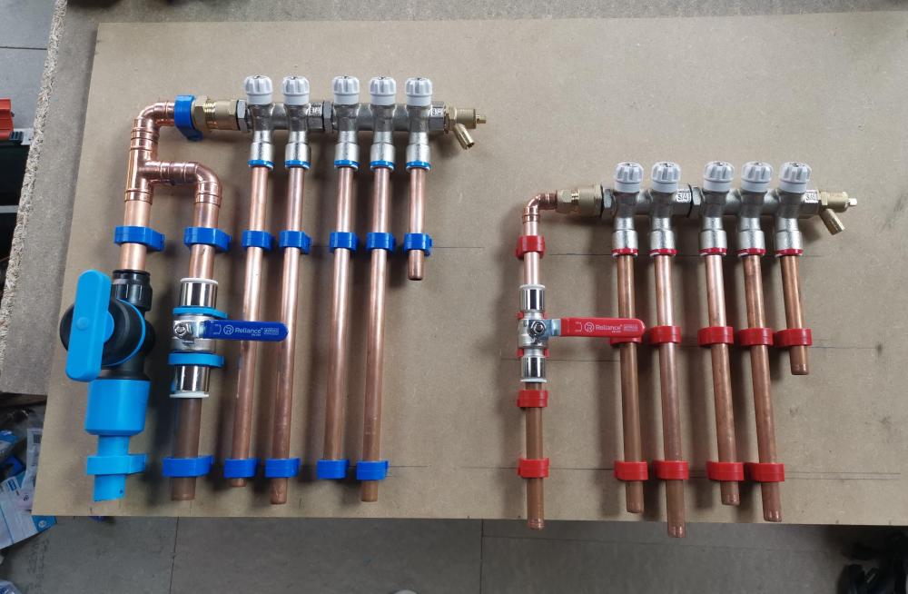
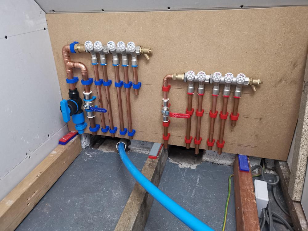
Almost seems a crime to put this in a cupboard... My plan is to change the copper tails to layflat, copper was just to keep my clips in alignment, so that it's just a continuous pipe with no joins to each appliance. Dedicated 22mm feed to the boiler. 1 spare on each, but room to add another 2 port to the ends if needed in the future. Any suggestions of changes before I solder this up? (Feeds close to the main due to space limitations under the floor so I had to bunch them up to fit between joists and through the gaps in brick.) As it's in the bunker with the ufh manifold I assume I'm going to have to lag up these colds to stop condensation @Nickfromwales?1 point
-
The flow rate at the combi boiler cold inlet is what pushes hot water out of the taps. As you are "stealing" from the rising cold supply to it, multiple times before it gets to the combi, you will likely see a significant loss in performance for the DHW output. If you run 22mm all the way ( to the last T-off ) and then drop to 15mm > combi, then effectively you have enough capacity in the 22mm pipe to service the "theft" as well as still having sufficient residual capacity to provide adequate cold mains 'potential' at the combi. Any instant water heater should have "cold mains priority" which is either achieved by running a dedicated feed from the stopcock to the appliance, or by doubling the capacity of the single supply pipe.1 point
-
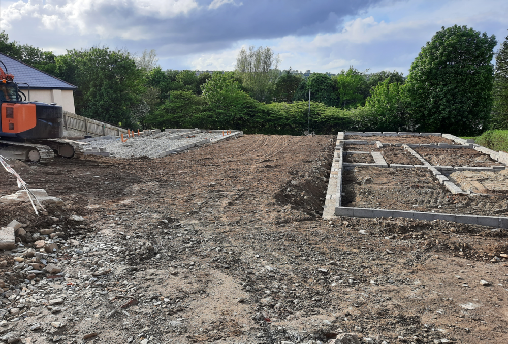
Here's ours, been in for 5.5 years now. This pics from a few years back, just after we cleared the debris from the build and started to get it seeded. I've settled on going with the S5 also, but am hoping to go without the rails. I'm just looking for a few similar installations to get a bit more confidence in attaching in that way1 point
-
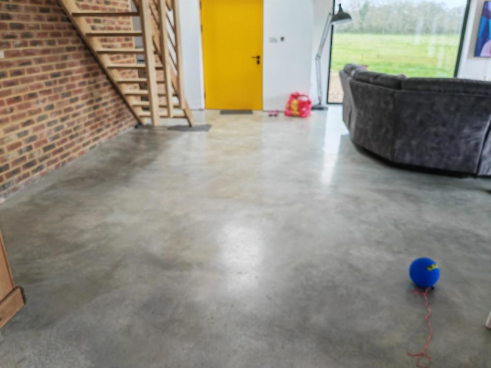
Thank you for all the kind words from everyone. I should definitely have started posting when we started the project - time flew by - it was very hectic most days, doing my day job full time and also trying to manage the build as best often late in the evening/nights), and also spending time with and looking after our children. Not sure how we did it. Here's a pic of our floor. It looks a bit "rougher" (not quite as shiny) in person but we like it and all its imperfections.1 point
-
Prob just best to get your mate / friend in, put the kettle on, and tell him it's time to admit defeat. If I showed this to my sparky, he would go and yank the main fuse and lend you some AA's for your torch.0 points
-
Re the connector blocks. He said he's using them to transfer things to the bottom CU to see if taking the rcd out of play stops the tripping. The power for the bottom CU is coming from the top cu I think. The main board is at other ond of house and an armoured is running to this point which is close to the middle of the house. It's a single story place. The added difficulty is that he is also a family friend which makes things even more awkward. Thanks for the advice so far. Tough to hear but aligns with what I've been thinking.0 points
-
Yeah I’m thinking this way . SE install of an additional dc SE battery looks like a simple plug n play option . What could possibly go wrong ?0 points
-
“ SWMBO home “ panic alert . Because when that happens any energy efficiencies go out the window …0 points
-
Yep. A groundswork guy I spoke to early on said he’d never use a kit build himself as he’d done the foundations for three previous houses where the kit builder went bust leaving the self-builders in the shit. One of them had to sell the plot as they couldn’t afford to build the house.0 points
-
We've found that before with the odd trade. Some people just can't leave a job partially done. In our last house the joiner did all the skirting for free as couldn't bare the thought of me doing it myself 🤣0 points
-
0 points
-
If you want low energy, then it will be a basic, 4 sided box. If you want 'eco' then it will be timber clad with grass on the roof.0 points






.thumb.png.388c71d5100dd326da9778225e6b94a6.png)


