connick159
-
Posts
108 -
Joined
-
Last visited
connick159's Achievements
Regular Member (4/5)
22
Reputation
-
we are on direct debit and pay them the same date every month. So only have this months due which I thought we could settle via the switch request with Octopus. I'll call Tomato tomorrow and see If i can settle up and then get them to approve the switch. If they don't then I'll just wait for Ofgem to do the change to SOLR and go from there. Thanks for the replies
-
Do you mean I could just hang around with them until the very last when Ofgem (or whoever does it) shuts them off fully and I get moved to someone else? I actually signed up to switch to Octopus Cosy earlier today but received notice from Octopus that... "Your previous energy supplier has objected to your electricity switch... We can't complete your switch until it's sorted and unfortunately it's not an issue we can resolve on your behalf. There's a few reasons why this may have happened: There's an outstanding balance with your old supplier. If this is the case, you'll need to settle the outstanding amount or agree a payment plan with your previous supplier before the transfer can continue...."
-
Administrator now appointed. Last chance to get out.
-
Mitsubishi Ecodan/FTC5 and Heatmiser UH8 UFH control
connick159 replied to cb1965's topic in Air Source Heat Pumps (ASHP)
Thanks heaps for the info. Not sure if i habe a buffer or its just an expansion vessel. Also, not sure what a strainer is but all the other stuff makes sense. I have manual mixing valves on both manifolds and pumps on both manifolds too. Not sure if i need them but the UFH guy installed them as standard. We had one guy do the ufh and screed and another mob do the ashp. Looking back, should have gone with the one mob. Thanks again. -
Mitsubishi Ecodan/FTC5 and Heatmiser UH8 UFH control
connick159 replied to cb1965's topic in Air Source Heat Pumps (ASHP)
Does anyone know the required steps to "unpick" a setup where the UFH8 wiring center and stats in every room have been installed? Is it a simple matter of removing actuators or do you meed to do something else? -
https://www.ofgem.gov.uk/publications/tomato-energy-limited-provisional-order I don't understand it tbh but seems they are in a bit of hot water. Im a customer and its been good since i joined in Feb. No probs or hassle at all but perhaps thats just around the corner given the ofgem order.
-
Full accounts were provided on 7th Feb by the looks of companies house register.
-
Just for Info for anyone still considering switch. I just switched from Octopus Agile to Tomato Lifestyle (battery, although we don't have one). I modelled my usage data for Jan before switching. For 896.376 kwh consumption in Jan Octopus Agile actual cost was £213.69. Tomato cost based on agile usage data = £133.80. Saving of £79 for Jan alone so... I did the switch via the tomato website. Switch took 5 days, was very smooth, no issues for us so far. 1st day on Tomato and we used 29.432 kwh - cost £3.30. Previous day on Agile we used 28.22 kwh - cost £9.20 Hasn't been many cheap days on agile last couple of months. We have a heat pump, no solar, no batteries and we try to load shift and use the ASHP over night when cheaper. We have underfloor heating in screed so we 'charge' up the slab over night and also now in the cheaper slots on Tomato which is 9:30am to 11:30 am as well as from 10pm to midnight (14p). No battery for storage or anything either so, if we did have a batt it's be cheaper still. Our kwh has gone up from around 30 to 33-35 but our cost have come down from anywhere between £7 and £9 per day down to £3:30 - £4 per day. Hope that helps anyone in a similar boat. (So far so good for our switch from octopus agile to tomato.)
-
Do you have batteries and PV which would be factored into you cost or just an ASHP only? I'm looking to switch as well. Only have ashp and are 100% electric for power and heating. Diolch
-
OVO which tariff first before heat pump add on
connick159 replied to connick159's topic in Air Source Heat Pumps (ASHP)
Would cosy be worth switching to, from agile, without any batteries? We only have the heat pump and nothing else. Will have a look at tomato too. Cheers -
OVO which tariff first before heat pump add on
connick159 replied to connick159's topic in Air Source Heat Pumps (ASHP)
Good to know, thanks. Is there any publicly available info on this? -
Hi all, Considering a switch from octopus agile to OVO with heat pump add on. We already have a smart meter and E7 so wondering if any experience / advice here regarding the best tariff for the baseline OVO tariff? Was looking at the "simpler energy" one via direct debit but notice they also have the PAYG tariff with day and night rates similar to the "simpler" one. Any thoughts or things to look out for. Anyone on this heat pump tariff with thoughts? Thanks in advance.
-
Can you fall a patio against slope of land
connick159 replied to connick159's topic in Landscaping, Decking & Patios
is 1:80 fall adequate for next to the house? a bit of mixed info out there. -
Can you fall a patio against slope of land
connick159 replied to connick159's topic in Landscaping, Decking & Patios
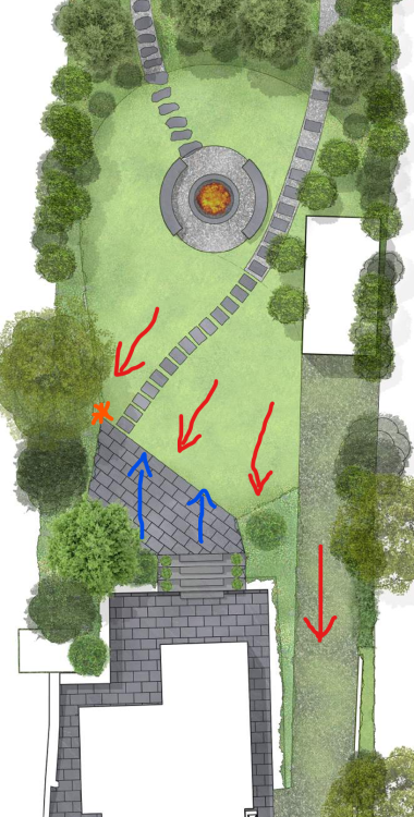
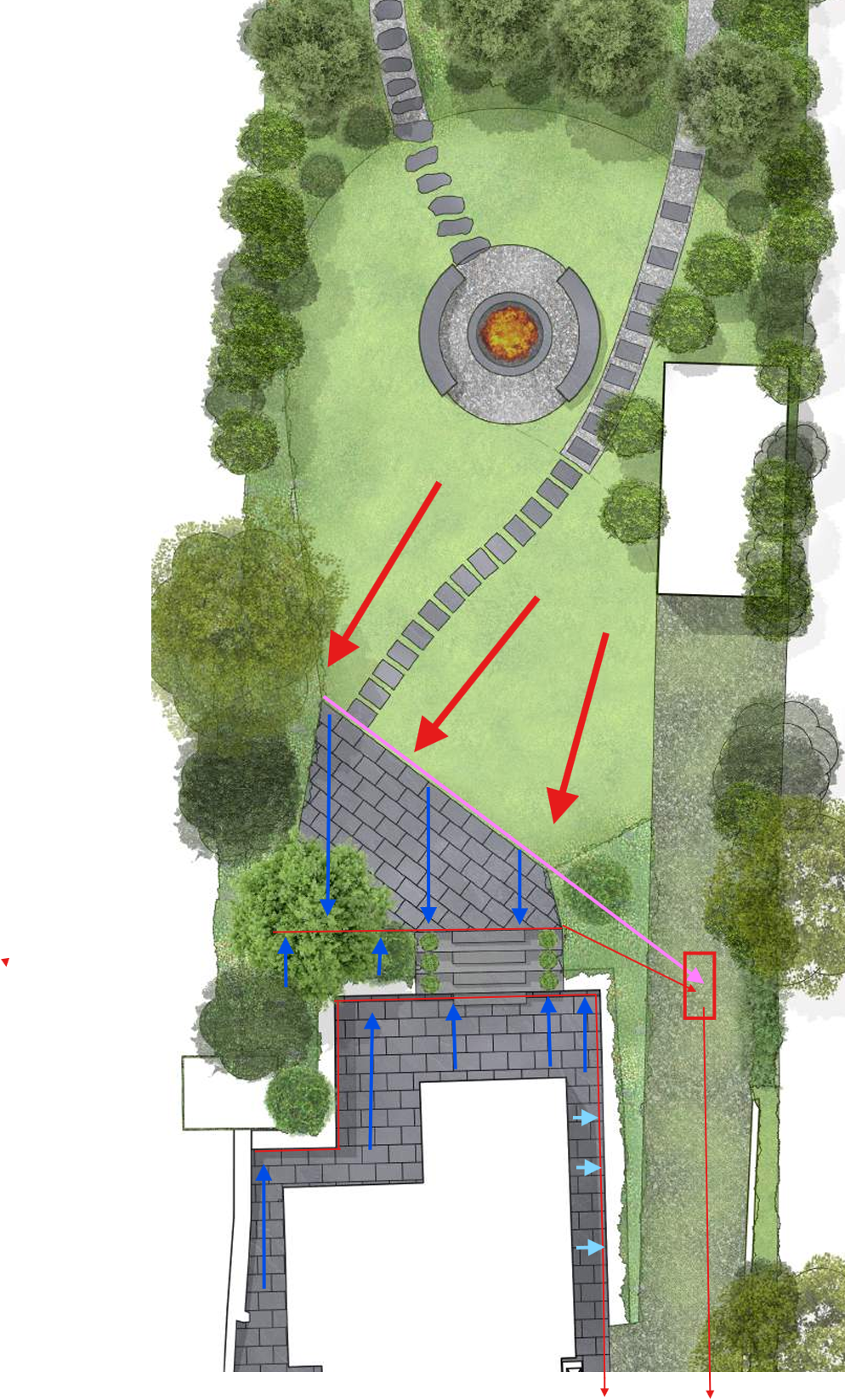
Here is the alternative i've thought of. This red lines are channel drains. Pink line is a french land drain drain. Thick red lines fall of land. Blue lines are fall on the patio. Which would you do?
-
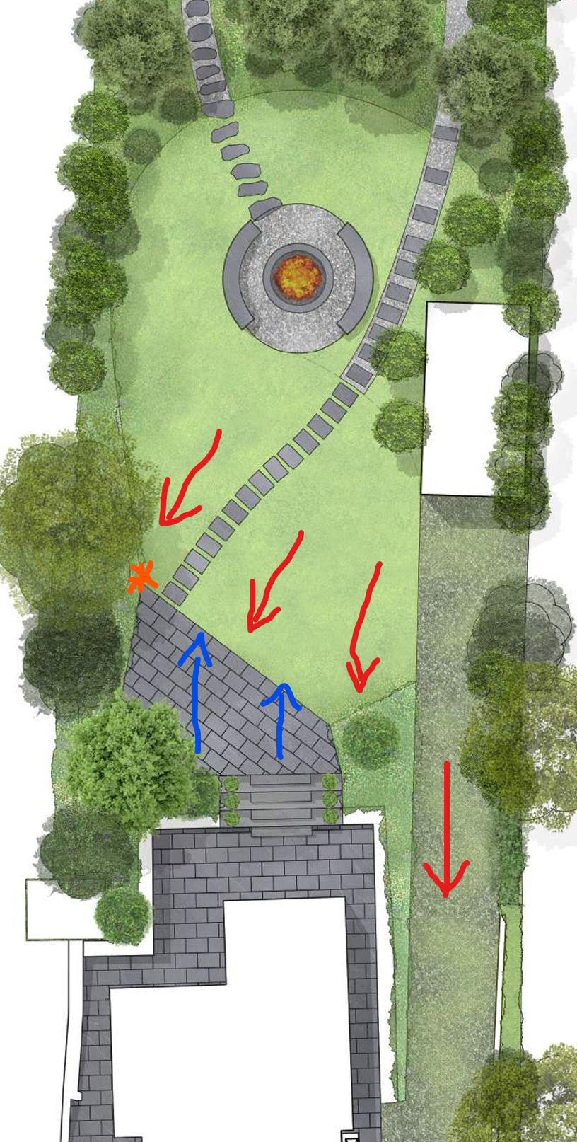
Hi all, I've got a concept design for a large patio area but struggling to work out if I should be falling the patio away from the house, which means its working against the natural slope of the land. i.e. is that even achievable? The blue arrows are the way i want to fall the patio as its away from the house. The orange asterix is 12 metres from the opposite corner of the patio (under the trees opposite) The red arrows are the natural slope of the land. It not a massive slope but if I do a 1:80 fall it means that the end closest to the steps need to be 150mm higher which then starts making the steps too steep over that area. One idea i had was to put in a channel drain just at the top of the steps, right across the patio and then using the natural slope of the land to direct the water into the drain. (There will be another drain at the bottom of the steps with the lower patio by the house falling towards that) Would love to hear the thoughts of members as to how they've handled similar design for draining on large patio's with the natural fall going back to ward the house. Is the top patio far enough away from the house not to worry about the fall going towards the house?