Leaderboard


Popular Content
Showing content with the highest reputation on 10/10/22 in all areas
-
I’d like to offer help to anyone who needs help doing drawings or designing their home or extension. I'm a Registered Architect with some time on my hands. I use my iPad and an app called Concepts to draw and have already helped out a few Forum members.5 points
-
First - the process overall should be enjoyable Don't get carried away with room sizes - you can end up with a huge houses. Decide things early and documented on the drawings, ideally before getting any pricing. Any change after the contractor has priced is a cost added - in many cases even a simplification of their scope. The more decisions you can make ahead of starting the build, the less stress during the build. Once you make a decision, don't change - it will cause lots of other hidden changes and snow ball, to more cost and delays Keep it simple, often things get way to complex and can ramp up costly quickly. Don't ask forums questions with open questions, as you will get 1001 answers all different, many not relevant. Do insulate way better than you think you need. Consider thermal bridging early on. Go as airtight as possible. Consider cooling if you have large windows, this can be direct aircon or solar shading externally. Question any large windows on the north face of the building as these are just heat losses - min 4x the heat loss of a wall (high performance triple glazed), generally more. Keep heating system as simple as possible. Do not zone the heating system, 1 zone ideally, a max of 2 zones. This will give your heat source an easy time and work better overall. Well insulated houses have very low heat requirements, many builders and heating companies will use generic formulas to size boilers radiators etc, none of which work with low energy housing. So check things yourself and be aware of your requirements, ask for help when needed.4 points
-
I buy these by the thousand Some companies won’t pay the extra most do 0 patching very tidy finish Simply skim over them 30 minutes per house to fit Boarders are happy everything tooled into boxes Electricians love them
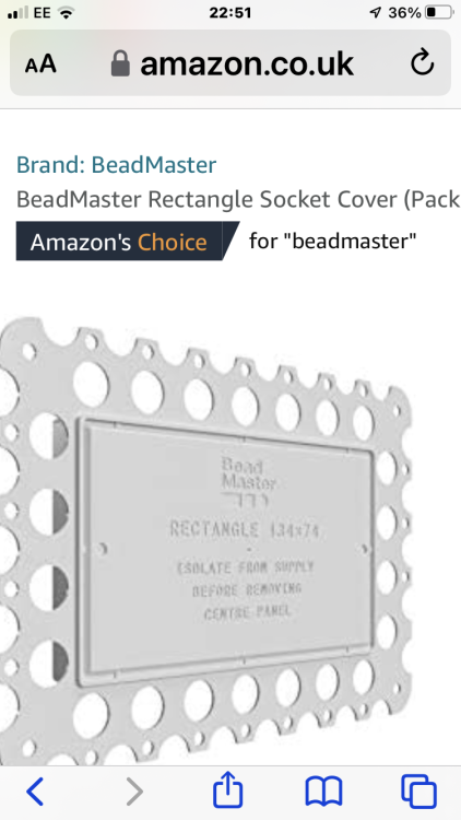 4 points
 -
Thought I'd do a short blog on the Polycarbonate tunnel we built. Our big field suffered with no storage, and location meant containers were very expensive to transport. so one option was to build a polytunnel, which we have planning permission for. again due to location, 500m from the coast 73M AMSL I wanted something sturdy. so looked at off the shelf packages. in the Highlands and Islands the PolyCrub is seen as the mecca. Designed in the Shetland isles, guaranteed to withstand 100MPH winds etc etc. due to the ability to get CROFT grant assistance on these, the price is, IMHO, artificially high CIRC 6K for 4M *6M.. this wasn't going to happen, so after looking at many photos I designed my own.. Basic principle is hoops of MDPE pipe secured to posts in the ground, then 3*2 timber used as horizontal support, with Polycarbonate sheets secured to this timber. the bottom sides are then clad. My design was to use 65mm Black MDPE pipe, and secure the timber with coach bolts and penny washers through the pipe. this way I get a guaranteed fixing that won't pull out , and it still allows for flex in the whole structure. 4m wide x 6M long, but this can be extended. My ground has bed rock close to the surface, 300-500mm below ground, so just knocking in post wasn't going to be secure enough to withstand the winds, also where I was sighting the tunnel its on sloping ground, so I couldn't get it level. I cleared the area to removed the top vegetation and a bit of the top soil. and dug 14 holes. then due to rock levels I then core drilled the rock to allow for the post to be deeper. We then set these in concrete, (at the same time as doing the slabs for the cabins.) The next day we had a look and I wasn't too happy with the security of the posts, so slight change of plan, we created a plinth. basically I used some 6x2 either side of the posts, with a slight angle, then filled this with concrete (again we used ready mix at the same time as back filling the treatment plant) this added about 300kg of concrete to each side, and joined all the posts together, and gave us a solid plinth at the side. No Photos of the next stage but we cut 7M lengths of 63mm pipe, this when placed over the posts gives approx. 500mm dwarf walls and a 6M polycarbonate sheet, giving a head height of around 2.3M. we used a plumb bob to get the centre line on each hoop and drilled an 8mm hole through the pipe and secured the top 3x2 treated timber to al the hoops. One thing we found was that the MDPE did not bend uniformly, this may have been due to slight errors with the posts being plumb. The resultant timber (which was not very straight), snaked from hoop to hoop. after head scratching and re thinking. I decided it was a poly tunnel and to get on with it. we used 7 lengths of timber jointed with half lap joints to extend the length to 6.5M. if using a clock analogy the timber was placed at 9,10,11,12,1,2,3 positions, with the 9 & 3 o'clock being 500mm off the ground, also ensuring the 9 & 3 o'clock timbers were approx. 5.8M apart circumferentially. Then it was a case of securing the polycarbonate sheets to the timber. each sheet is joined with some soffit H joint strip. (you can buy a clear joining strip for the sheets but for a 6M length it was around £65. the H strips proved extremely difficult to connect the two sheets together, or should I say impossible. so I cut off the back edge on one side and used some glazing sealant. this way we could attach the strip to the polycarbonate prior to bending over the tunnel. and each sheet 'H' strip basically lapped over the previously installed sheet. day 2 we had the basic structure. It was noticeable that the curve was not symmetrical, so putting the door frame header in by securing to timbers at 11 and 1 o'clock was not level. I overcome this by using a ratchet strap attached to the 11, and 3 o'clock timbers and tightening until timbers at 11&1 o'clock were level. I then put the two door jambs in (concreted at the base) and cut to the length required and secured to the header. This worked and the tunnel was now more cylindrical. I framed the rear by baring 3x2's off the horizontal timbers. Last steps were to clad the base, I used 4*1 treated timbers that were screwed into the MDPE pipe and wooden posts. then used strips of visqueen to create a more sealed dwarf wall, this will help prevent driven rain from the winds getting inside. over this I used Larch timber backs* to create a vertical cladding All in with hardware, polycarbonate, timber, concrete the project cost £1200. not cheap, but its solid as a rock. It withstood the first Autumnal storms this week with winds hitting 50MPH. Its also very warm inside, even now as the temperature is falling. Larch timber backs are the offcuts from the saw mills and are reasonably priced as scrap. we purchased a pack of timber backs, approx.40 lengths of larch timber with bark in 4.8M lengths for £100. these are not uniform and taper etc, but as i only needed 500mm lengths it was straight forward to make it work.3 points
-
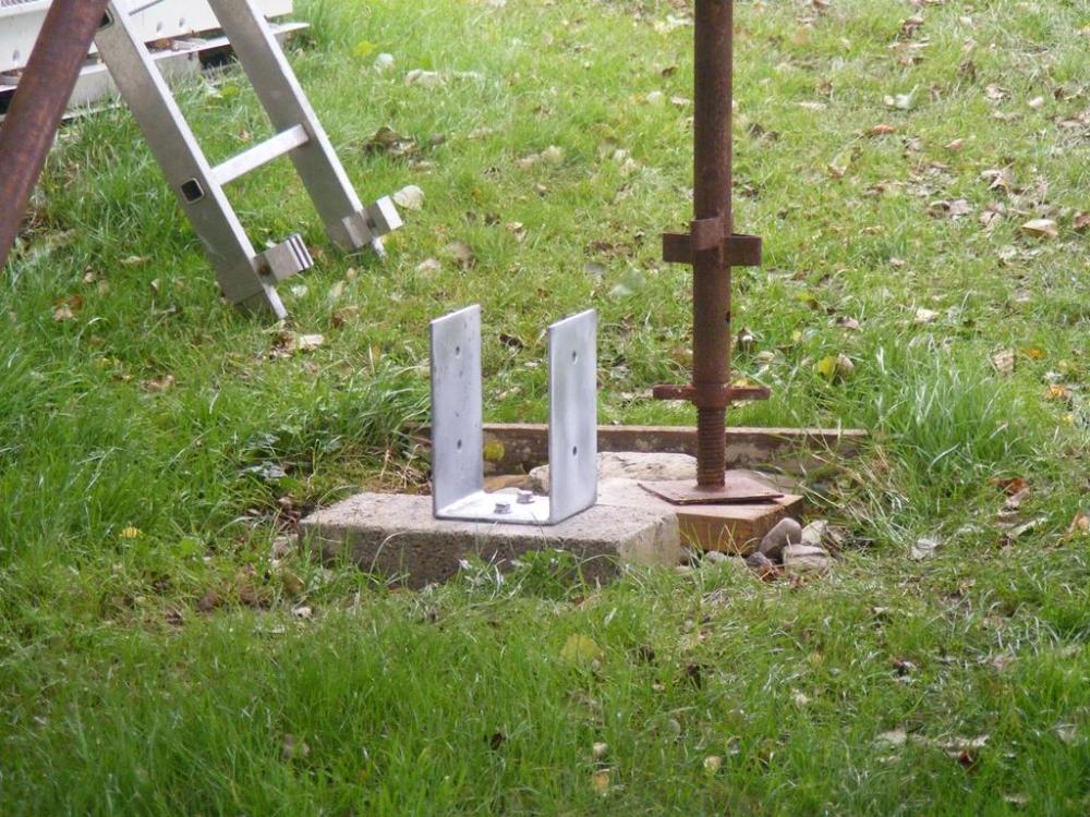
Yesterday evening my neighbour knocked on the door with two post feet. Today I have fitted them. Studs set in the blocks with resin, nuts not yet tightened down until it has had a good while to set properly.
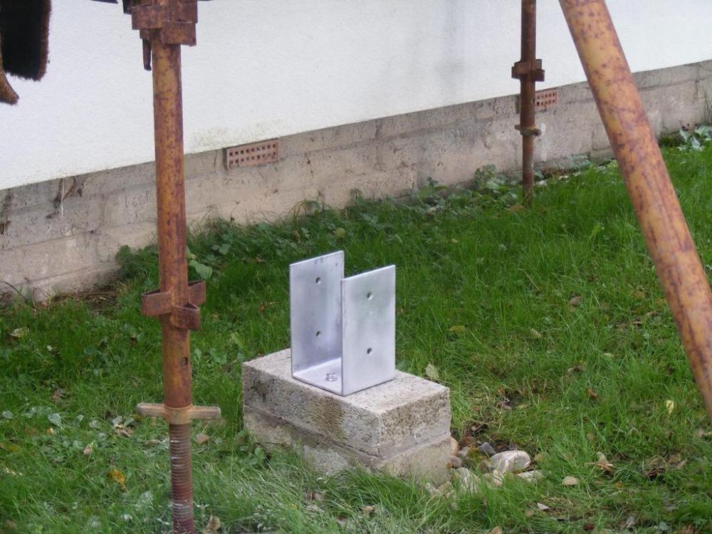
 3 points
 -
Frankly it’s knowing what you want/can afford.3 points
-
I've seen plenty of cautions about creating hybrid warm roofs A thorough condensation risk analysis should be carried out rather than just winging it.3 points
-
Had a sh!t week so basking in the glory whilst I can: My DIY chamfer tool did the job. Tbh a decent chamfer, even if not perfect like mine will do. Some silicone spray helps.2 points
-
There be gems in my mega thread!2 points
-
Tesla 109-112mm Rubber-Lined Pipe Clips Black2 points
-
Knowing how much you can loose: Partner Children Friends Dignity Time Body Parts Tools . . . . . .2 points
-
As promised another update, following many tweaks and a firmware upgrade from Solis. So the existing problems were: Whenever the battery isn't at 100% SOC, it pulls an amount of power from the grid, somewhere between 60W and 100W Even when the battery is actively charging, it still pulls the same 60-100W from the grid, regardless if there is enough PV power to charge the battery and cover loads at the same time. Once the battery is 100% SOC and im generating PV more than my load, I import 0W. Pulsating loads (such as induction hob) the unit can find hard to track, due to their pulsing nature, and the delay in reading the CT clamp and acting upon it. The firmware upgrade was to fix the pulsating load issue, it doesn't completely resolve it, however it is much better tracked now. Solis reduced the polling time for the CT, so it is polled more often than before. The problems with the excess import of between 60-100W remained, however Solis put some variables in the new firmware which allowed them to place an offset, we tried many different values and eventually stopped at a 65W offset, now the grid connection fluctuates between +40W and -50W which overall has fixed the issue as good as can be without draining too much of the battery power. Oddly since adding the second US3000C module, my overnight usage (no PV input) has dropped from around 0.35kWh to 0.2kWh, why i'm not sure but no complaints from me there!! Now have 6.6kWh of usable capacity, to note the original US3000C module had just dropped to 99% SOH, manual states to use the newer module as the master, which I did, so its now once again showing 100% SOH, and the 1% drop of the older module is handled internally. Upon connecting the new battery, the old battery appeared to receive a firmware upgrade, as it restarted a few times before staying on. Current yearly graph is looking good, still exporting a lot of power, but at least I'm using what i can now: Shown above is a daily example of the battery charging and discharging. This was after a particularly cloudy day which only just saw me reach 100% SOC for a mere moment. The negative battery power denotes power draining from the unit, with positive being a charge. This is the corresponding grid data for the same day. Previously (March 2022) I reported total import of 48.3kWh. Clearly its impossible to compare with another month, and we will have to wait til March has been and gone once again, however here is the monthly data from April onwards: April - 41.2kWh May - 18.4kWh June - 17.1kWh July - 18.9kWh August - 18.1kWh September (So far) - 18.0kWh The tweaks to the system were finalised on May 5th, just checked my emails from Solis and that was the last contact, so April shows another month before the changes. Full credit to Paul Carpenter, the European Engineering Manager as Solis for sticking with me on all these changes til we found the sweet spot! Hope this provides some good info for someone out there thinking of installing battery tech. I'll post another update at the 1year point, though probably 1year from the tweaks, so May next year, and then I'll also be able to comment on my AQ for the import.1 point
-
I'll get SWMBO to administer them1 point
-
Yup. 👍1 point
-
Just chuck an 80 grit flapper wheel in the grinder and dispense of these acts of tomfoolery…..1 point
-
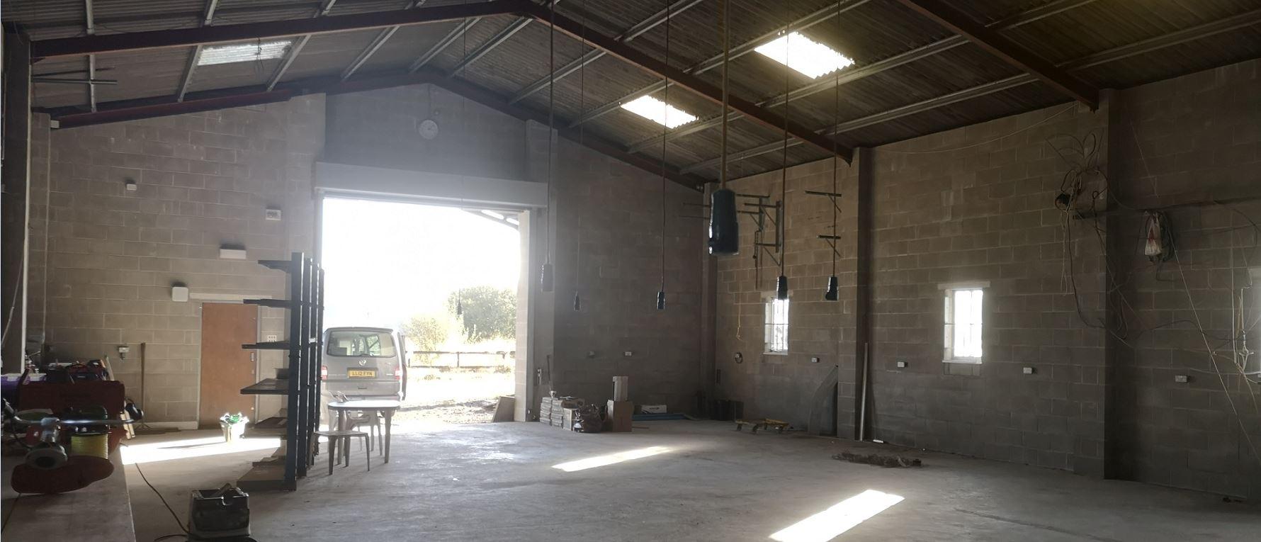
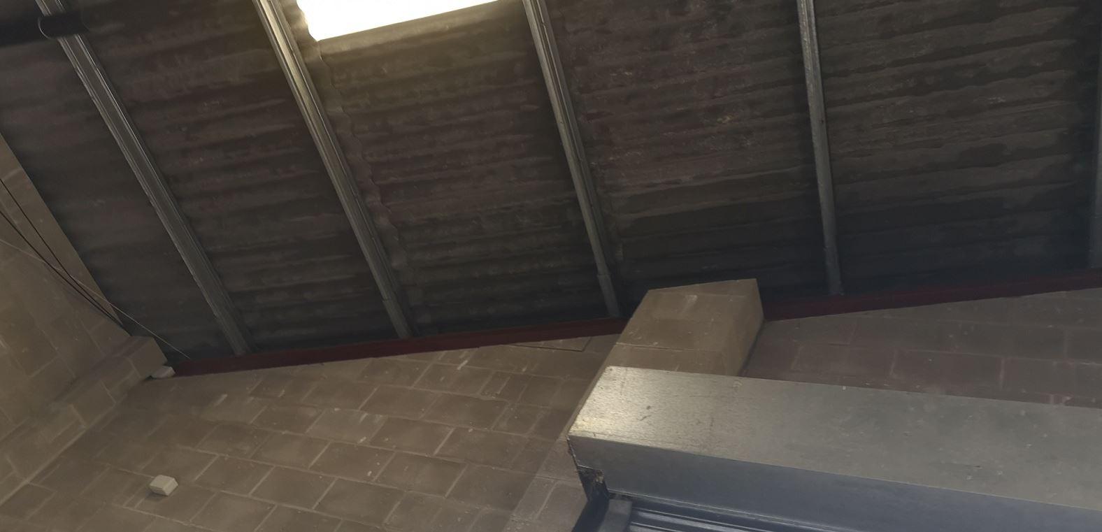
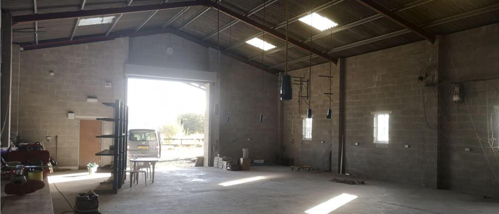
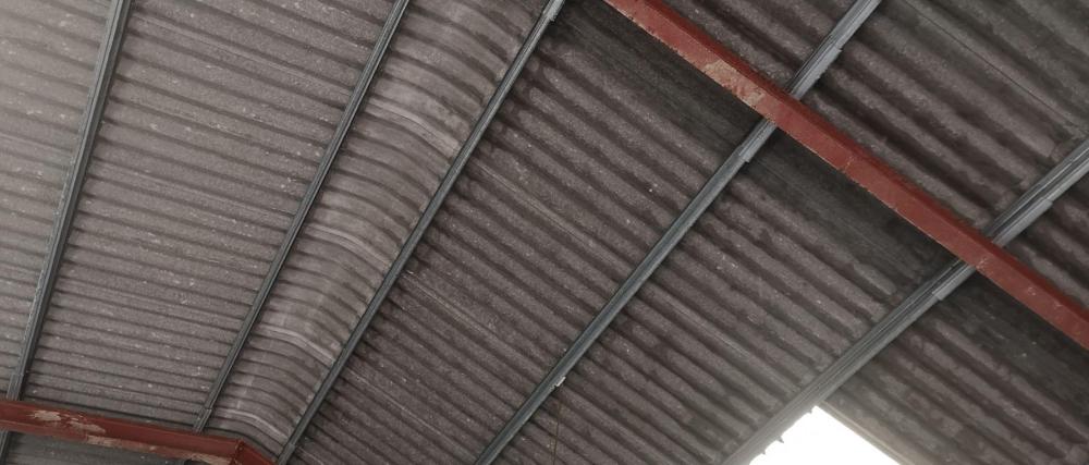
Holy thread resurrection! Im back. What i neglected to mention last time was i didnt quite own said building. But i do now Maybe a thread on the tired, poorly put together cottage that i need to do some serious work to is in order? But a man has to get his priorities in order doesnt he? So lets start with the shed. As always, fabric first, and before its completey full, i need to insulate the roof. Question is how. At as low a cost as possible. So far, this looks like my lowest cost option https://www.trade-point.co.uk/departments/knauf-space-blanket-loft-insulation-roll-l-4m-w-1-14m-t-200mm/182138_TP.prd Held to the roof with wires. However, my concern here is that given the roof is corrugated, am i likely to get condensation forming in the "peaks" which would then ineviatably run along the blanket till it finds a join? As you can see in the pic, currently, overnight it gets damp on the inside, then the sun comes out and it burns off. Light grey dry, dark grey damp. Thoughts? I was advised by a freind who does commercial building roofing, that they often put unbagged rockwool on top of the roof and "over roof" it, so one surmises condensation forming is unlikely, otherwise it would just get wet? Other options? The only viable one ive come up with is spray foam. Clearly that does away with the risk, but £10-15k to do it

 1 point
 -
My advice has been 100% accurate . @Thorfun has faith in my (in)ability .1 point
-
How about using old pallets (it’s what I did) plus some old tin roofing.1 point
-
There be lives wasted in mega thread1 point
-
This and plenty more on u tube1 point
-
Just go for it. If it fails, work out why, then try again. It is only a woodshed.1 point
-
That is really impressive!1 point
-
and a bit of kudos where it's due to @Onoff as his tip about the SF mitre box fitting the 110mm soil pipe was spot on! I bought one and my cuts have never been squarer. thank you @Onoff. you're a genius. but I am having poor results with the chamfer tool I bought. https://www.screwfix.com/p/metex-10mm-shank-drill-mounted-pvc-pipe-chamfer-tool-110mm/876pv?_requestid=421611 I must be doing it wrong as I get part of the pipe chamfered nicely but other parts not at all! I'm trying my hardest to keep the drill square to the pipe but nothing I do seems to work. I've gone back to using an angle grinder to smooth down the bits the chamfer tool isn't chamfering.1 point
-
Good boy. 👍🤣1 point
-
cool. and I can just buy a long length of threaded rod and cut to length?1 point
-
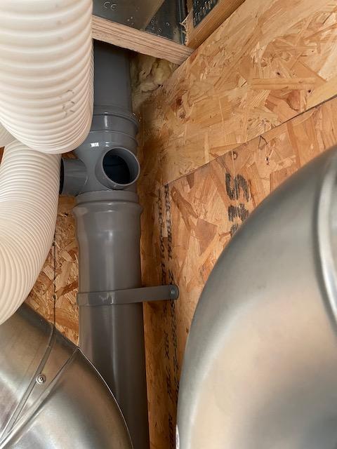
@pocster and @Thorfun those hangers, you get a length of threaded rod and cut it to length then you can make any hanger you want. As @ProDave said ,that bit in the loft is a bit horrid, the first bend coming from the vertical pipe need cutting back as you have a section of pipe with a back fall on it. If it looks right it generally is, if it looks a bit fugly then it’s normally not to flash. That bit in the loft is fugly.1 point
-
I'm glad you're here Dave! it is downhill but I didn't think it'd matter as it's just a vent pipe! didn't even think about condensation of leakage. I will fix that tomorrow. THANK YOU!!1 point
-
You don’t need him . He’s busy installing PV - you got me !!! 😋1 point
-
Is that a camera angle thing or is there a bit of "downhill" pipe? If so you have created a trap that could fill with condensation or leakage from the roof vent over time.1 point
-
They are ok . But as you said thread length can be an issue . I also used metal strapping . Cant remember where I got my hangers but just looked Screwfix - do them 👍1 point
-
yeah, much better idea that chucking a turd down it. already planning a UP320 for each en-suite. have done much reading on this forum and that definitely seems to be the one to go for. me too!1 point
-
first bit of soil pipe done today. managed to join it up with our tile vent so I guess I now have an SVP. 🙂 above is the branch for our en-suite toilet. measured at 230mm center from FFL which seems to be standard-ish. it's only about 400mm from where the toilet will be so there shouldn't be any major dramas if I'm a little out I hope! this then goes down through a service void where the ******* MVHR pipes/ducts are. damn they are annoyingly always in the way. I think I'd have finished hours ago if I didn't have to take 3 MVHR pipes off a manifold to move them out of the way to get the soil pipe through. anyway, it's done now and I'm happy with it so far. MVHR pipes getting in the way of the boss fitting I installed. I was hoping to get to use 2 of the bosses but can only get to one of them now. will just have to run the shower, bath and sinks into the same waste pipe into the single boss hole. will try and find a turd to throw down to test it.
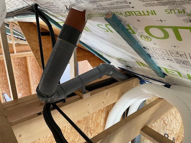
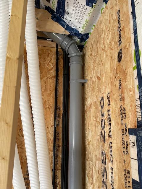
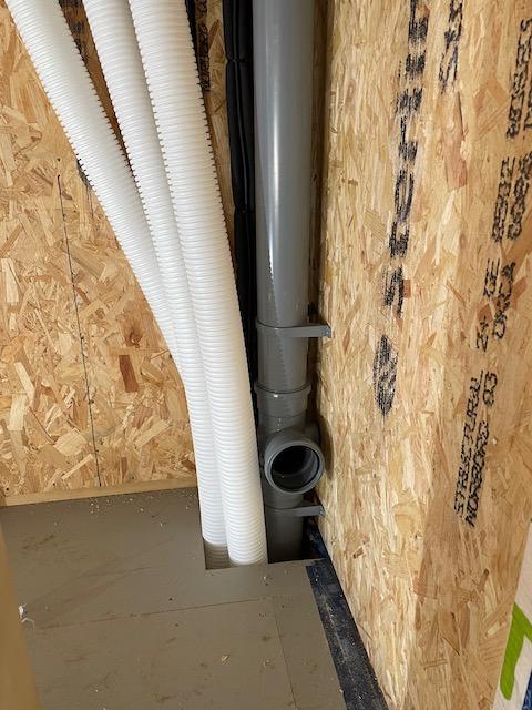
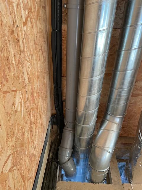
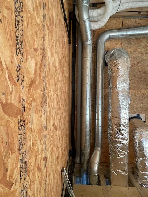 1 point
 -
I am indeed. only had to go to Screwfix/Toolstation twice today to pick up more things. 😂1 point
-
so I've done as you suggested and kept the 'Floplast' writing and logo the right way up but I'm still at a bit of a loss as to how it makes a difference? as you have double jointed sockets that have rubber seals at both ends so have to be able to have a rubber gasket at the bottom in some situations. so how is the double socket different to the single socket? do they put the rubber in facing the other way round? it doesn't look like it and it doesn't make sense!1 point
-
Building your first home is a big lifetime decision. It’s easy to get swept up in the whirlwind of options which can cause you to make common mistakes that you might regret later.1 point
-
I reckon a SCOP of 4 to 5 is achievable for the latest models, well installed and set up. I just re-worked my numbers based on these latest costs (including daily fixed rates) and my ASHP is saving me £1,148 pa with no heat loss saving measures. Yes granted the old boiler was probably less than 80% (perhaps as low as 70%) efficient, but that is probably no different from the average uk household, still operating at crazy flow temps up in the 70s degC (the legal max is now 55degC). Even allowing for 70% efficiency I'm getting an implied SCOP of around 5.1 point
-
We initially completed this for Building Regs:- The Water Calculator And made it fit, this was suitably accepted for Building Control, Water Connection and the Warranty.1 point
-
Think of the future . Increased gas / electric costs . Over insulate for sure . Pv and battery I think an essential. wet ufh ; ASHP . Triple glaze . Of course budget may be an issue …. The journey is the destination.1 point
-
Don’t forget that you will need through ventilation for BOTH cold roofs. You will need continuous low-level ventilation to the main roof at the junction of the main and flat roof. You will need low and high-level through ventilation to the flat roof. Personally I’d get a condensation risk analysis done - quick phone call to Kingspan - than muck about with trying to get ventilation. Whichever option you go for the main roof will need ventilated along the junction of the flat and pitched roofs.1 point
-
I had the following condition " Prior to the occupation of the dwelling, details shall be submitted to and be approved in writing by the Local Planning Authority to confirm that the dwelling has been completed to meet the requirement of 110 litres of water per person per day." The Ecology were happy with this . Not sure if this helps or not?1 point
-
Keep the floor plan/building shape as simple as possible. Don't go 1.5 storey unless you choose attic trusses. Avoid valleys and structural steelwork. Insulate, insulate and insulate some more. Naturally ventilate. Avoid air-conditioning if you can. Orientate the house to maximise natural light and heat. Consider renewable energy sources. Establish a budget and stick to it. Use an architect-a real one! - one who you can work with to deliver what you want.1 point
-
To be clear(er), by dry trap I mean something like a Hepworth Hepvo or McAlpine Macvalve etc.1 point
-
Ah, my adapter didn’t have rope in it, hence why I fitted some!1 point
-
In a pitched roof insulation between and over the rafters (hybrid roof) may be acceptable with a careful choice of balance of insulation resistances and use an AVCL. In a flat roofs however this is not good practice. In above roof section there should be an AVCL (polythene for mech fixed and bituminous for fully bonded) on the ply deck. A foil backed plasterboard ceiling should not be relied on. Check insulation manufacturer instructions & BBA Certs1 point
-
Ventilation gap, batten cement board, cladding. But. I still wouldn’t do it, you need to look at the weight of the cladding, the load the cement board can take and all sorts. Go for a cement based plank or upvc, that area of the house will get all sorts of weather chucked at it, not a place for stone in my opinion.1 point
-
It looks very narrow to me, either as an extension or a garage. Surprising as there is plenty of room to make it wider. To be honest I see possibly enough room for a whole new house? Have you investigated that possibility?1 point
-
Raised tie trusses might give you a lot of the effect for less cash but won't be truly vaulted. Otherwise you're stuck with collar ties or lots of engineering cals and most lightly steel.1 point
-
Bar bending and reinforcement quantities! Have written this as I hope it helps all who are doing everything from ICF, piled extensions or just using rebar. I often do these on small domestic projects. I sell this as an extra to the Client by discussing first what type of builder they may want to employ. Take two cases: 1/ A house extension.. a few piles with a ring beam. Here your local builder (or you) could maybe get a piling contractor that leaves the pile heads. These are commonly designed at SE stage to be up to 75mm out of alignment and still be code compliant. Next the builder has to figure out how to connect the piles to the ring beam, the shuttering to say get the concrete cover right and all the bars in the right place. Now your local builder may find this a challenge. I say.. hey I'll do the schedule and a shuttering detail. Your builder can then send my schedule to the benders for pricing, make the shuttering and I'll nip by and check it before you pour the concrete. If you want the builder to sort it all out it will probably cost you more than getting me to lay it all information wise out on a plate for the builder. All they need to do is send my schedule out for pricing.. no hassle for them and if no hassle less tends to be added to the price. Or you can get a ground worker that will sub out the piling and do the ring beam.. but someone has to coordinate all this and that is something that comes at a hidden cost.. and you have to take a leap of faith that they are doing it correctly. Better to spend more on good pragmatic design info than have a bad day when it comes to the concrete pour or worse.. once the concrete has been poured and you discover all is not as you expected. Stepping up to say an ICF basement. Here I would push the Client to pay me to do the steel (bar bending) schedule. In fact I would be reluctant to do the job unless I had sufficient design control over it and be able to check on site. What folk don't realise is that when you bend rebar it is not an exact science (bends vary a lot!) and that you need to be very careful to maintain concrete cover, the correct lap length and make sure the concrete can be well compacted at particularly the corners and junctions as that is where you often get leaks. The folk that provide the ICF stuff don't cut you much slack if your bars and in particular the bend radius is a little off. The steel fixer will use what they are provided with and while they will often do their best they can't make a purse out of a pigs ear. Remember that rebar is very heavy and if a rebar cage falls over it could kill someone. I want to make sure that the tying of the bars and temporary stability bracing will be sufficient for it to stand safely during the construction phase. ICF suppliers.. their interests / priorities are not the same as yours when it comes to rebar and so on. Yes some SE's don't do schedules.. years ago it was part of an Engineers training to design a concete beam / slab and produce the bending schedule.. I still remember learning how to do it. The main thing for me is that if I do it say for a basement or say ICF, a retaining wall I have to really look and draw/ model how it is going to fit and if it can be built /poured. It's almost like a last design safety check as when you have to sit down and do the schedule / shuttering you can spot things that you may have missed. It's like another design review/ safety check. If it can't be built as per the design then it's not safe. I could pass design responsibility to say.. well who is going to carry the can.. that is what you need to ask. The sad reality these days is that few designers want to carry the overall design responsibility as modern Clients are often not willing to pay for what they percieve as an extra. Why.. because modern professionals often don't explain (and have often not been taught how to) to a client how they can make savings at the end of the day. I minded to blame the telly.. too much Sarah Beany, Homes under the hammer and Grand designs etc .. well I'm not going to blame myself? If you have the skill to convey to a Client that your way is the most cost effective, efficient and delivers and the Client is not of like mind then you need to walk away from that Client, let them get on with on it. Projects like that often only lead to disappointment on all sides.1 point
-
Power+ alarm:Power+ offline The Power+ is the inverter/vfd that drives the compressor. It’s connected to the main Carel pCO control PCB via rs485/modbus. This error would imply that the Power+ hasn’t powered on properly, so isn’t responding to commands from the pCO.1 point
-
heya, I built a 2.4x4.8 shepherd hut without a chassis last year, it used 150x47 joists for the base frame, but i stood it on 100x100 posts notched around the frame placed every 1.2m and the frame was 400 centers. Its pretty solid. I wasnt using graded timber, which may make a difference, but rather than be sorry i overbuilt it. The peripheral frames were all doubled up too. I'd not trust 4 posts for that, but maybe put in some mid point posts if you want to keep the feet number down.
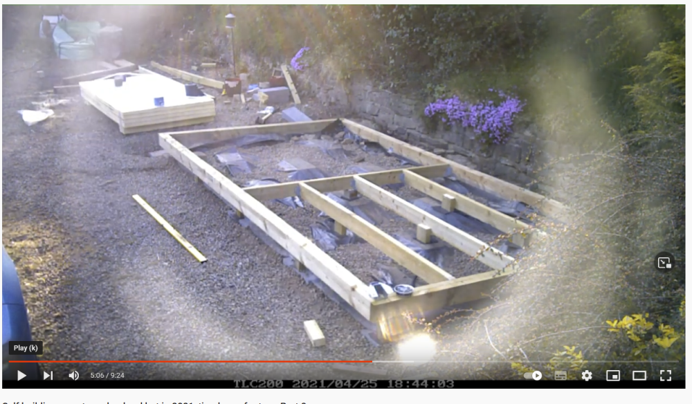 1 point