Leaderboard
Popular Content
Showing content with the highest reputation on 03/31/22 in all areas
-
3 points
-
In my experience the utility firms don't strictly enforce the separation distances where it is not practical. Water like to be 750mm deep, even though they have some of theirs at 400mm. Otherwise you can mostly do your own thing.2 points
-
Another thing that helps with design. Try to visualise the air flow through the house. You want "stale" air to flow out of habitable rooms and travel via communal routes to extract points. You don't want two extract points competing for air coming from a single outlet, you. end up drawing air in to a supply room. rather than out. Somebody spotted this issue in our build and I quickly changed a dressing room to extract so we'd have better air flow out of our master bedroom.2 points
-
Think of your customer. All Matters Reserved gives the most flexibility. And your workload: quicker, cheaper.2 points
-
I'm going to be annoying here and not entirely answer your question, but instead pick up on something slightly different 😉 I notice you have acoustic insulation shown in your drawing. If you're looking for decent sound insulation within this staggered wall, I'd recommend you use a continuous roll of insulation which zig-zags behind the staggered studs. 25mm acoustic insulation isn't going to do much and with the current design you only have 8mm between staggered stud and plasterboard so too narrow to do anything. In that sense, depending on the noise levels you want to achieve, you might be better using 38 x 89 studs which are installed on 38 x 140 studs at top and bottom. You can of course go for 38 x 63 and increase the gap behind each stud using 50mm insulation but I'm not sure how quiet the wall will be. Remember though that your stud spacing will be 600c/c at each side of the staggered wall so in effect 300c/c (Just noticed PeterW already said this) Most places will supply C16 cls in my experience.2 points
-
This site is very helpful. It summarises the issue accurately and links to further resources. A goldmine for you .....2 points
-
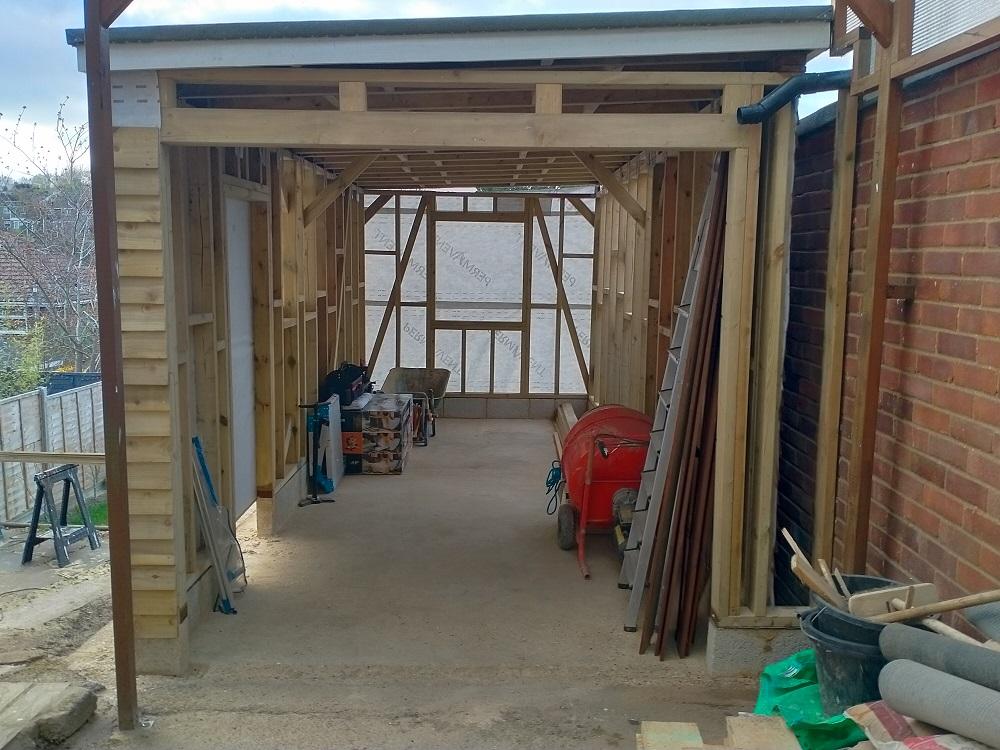
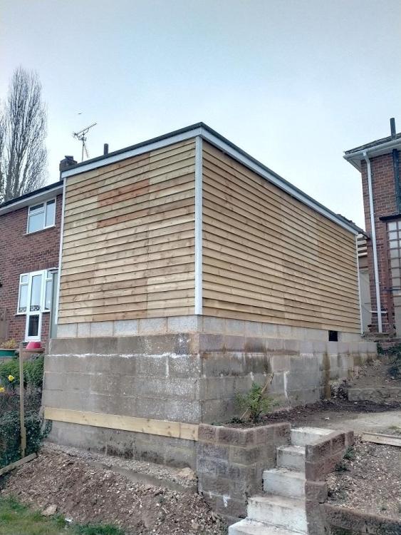
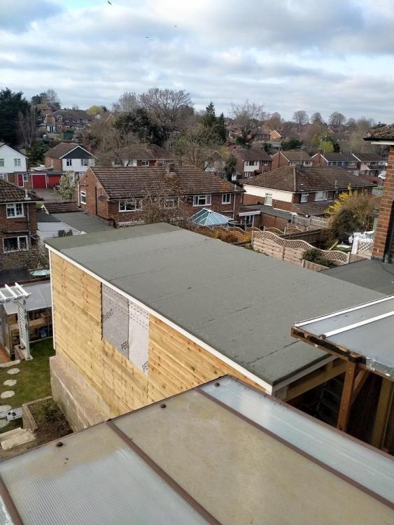
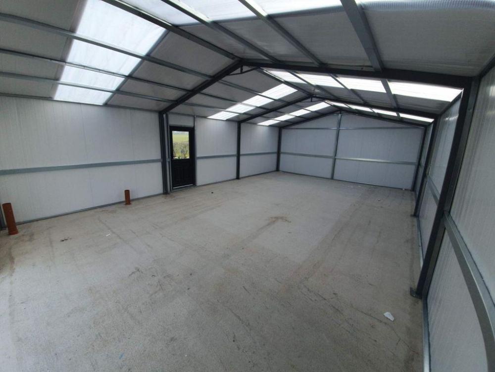
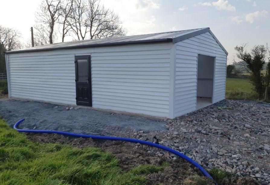
Hi everyone. Just another update. The roof has now been completed. Building a flat roof is a lot easier than a apex roof. Feather edge boards have been used for cladding for the sides of the garage. The window and door will be installed later on. For the guttering I would like the down pipe to end in a green water butt, I think this would be a nice feature.The project has been a huge learning experience, it was only 2 1/2 years ago that I purchased my first cordless drill.2 points
-
A good point. And big knots and shakes too. One of the plus points of Wickes, as long as someone hasn't already taken the good bits. There is often more out the back. I once went into Travis to do exactly that, and the supervisor complained that we were taking all the best bits. In fact we took it nearly all, including a 2x2 that rotated 90 degrees in its 3.6 length. Then he complained that he had no saleable wood left if anyone wanted any. Straight wood is good. It grows straightest in very cold places like Siberia and Finland. Siberia is a no-no of course.1 point
-
I have found it is handy to select the timber in person so you can weed out the twisted and banana shaped ones. Some batches can be dreadful. The drawing needs twice as many studs.1 point
-
Yes, roughly true. Difficult to look back now and recall the challenges. After a while it seems easy. Does 3D too I find LiveHome more intuitive1 point
-
Great advice above, especially this... My MVHR design & install process had a few distinct phases.. BTW this was all trial and error for me, made loads of mistakes along the way. 1) Airflow strategy: Effectively a refinement of what you've done above but using the suggested principals above.Start with a supply per habitable room and an extract per 'wet' room (kitchen, WC, bathroom etc) Forget about ducting right now but draw arrows on how air will go from supply to extract on your floor plans, navigating doors etc. You should then spot any 'dead' spots and address. Also think about additional extracts near a recirculating hob extractor for example if you find that more than a few metres from the general kitchen extract (as we did). 2)Then think on how you'll join these together and do duct runs to the intake and extract manifolds - irrespective of length we used two runs per extract and one per supply. Retrospectively we should have doubled up ducting on a few very long supply runs but not a big deal really. Duct routing can be diagonal through web joists (shortest path) but will need to navigate around steels and other structural elements. They also have a fixed bend radius which can come into play when you have a lot of them coming together at the manifold. By this stage you should have an idea on total duct length. It usually comes in 50m lengths so round up and maybe add an extra one for unforeseen circumstances. You'll also understand how many ports your intake and extract manifold will need (one for each length of duct) and where these will live. You then need be able to calculate the wide bore steel duct, including bends, angles etc to get from your manifolds to teh MVHR and from your MVHR to external intake / exhaust points. These last two will need insulated as cold air from outside will be coming in one and out the other so they will attract condensation. 3) you're more or less ready to order ducting materials. Steel duct will need adhesive and tape for the joins while the flexible duct just slides into position and is secured with supplied clips or catches in the plenums / manifolds with o-rings making the seals airtight. Silicone lubricant spray is a must to make that an easy job. Builders strap is handy for supporting all kinds of ducting if there is not sufficient local support (like a web joist). 4) At this stage you should have an awareness as to whether steels need penetrations pre-fabricated or where there may be a clash of space with other services (usually foul pipes). Sometime you only realise this when the structure is up which is why having some redundancy in your duct supply is useful. 5) I've not considered any electrical aspects here - your unit will need a 13A supply (plug top or isolated) and you may need to run cable for a secondary wired controller. Boost switches etc can be taken care of by your electrician. You'll also need to run condensate from the unit to a foul drain. 6) install should go to plan but as above, it's easy to miss an obstruction and need to go a longer way round so be prepared for that. This is also where you finalise position of the plenums (wall or ceiling) as structural considerations may dictate that - make sure plenums are installed with the duct ports pointing in the direction that the duct will be coming from to avoid sharp bends. 7) once all plenums are in place (and I faffed about a lot with this) start to run duct from the manifold area to the duct. I found this much easier that the other way round. I used to screw a plank across a doorway and through the centre of a spool BEFORE cutting the ties on the spool so that it could unroll somewhat easily. If you just open the spool, it will knot up very quickly. Equally, pre-cutting lengths is asking for trouble as you risk them being too short or having too much waste. Once the end of the duct is secured in the plenum, cut a generous length next to manifold and move to the next one. You just need to label ducts as intake or extract at the manifold end as a minimum (I used red and blue sharpies). Not a whole lot of use labelling per room. You can then trim each duct and connect to the relevant manifold - this was harder that it sounds as too long or too short and you won't make a good connection. Some trial and error here (obv going from too long and trimming incrementally until perfect fit). '8) Ducting the wide bore stuff is a different game - four connections to make and depends on where your external intake, extract, manifolds & unit are. Leave room to insulate the external ducts. 9) At this point you're done from a first fix point of view. Cut plenums flush to the plasterboard to make life easy for your plasterer and pop in the duct covers. You probably won't mount the MVHR unit itself until second fix. Good luck!1 point
-
If it easier to route you can have supply valves near a door, but you have to use coanda supply valves, which are wall mounted near the ceiling. These will throw the air across the room, as the air coming out sticks to the ceiling for approx 4 to 6m. You have baths and showers, the extract valve should be either above the shower or bath which ever is likely to be used most, but position away from doors or windows. All your downstairs supply nozzles are too close the windows and doors. Our longest run in 90mm is about 15m, any more than that you are running the mvhr harder to get the flow rates required and would require 2 supply pipes. Your kitchen extract, I would move further from the hob, otherwise it could get grease laden quite quickly. As said place an extract to make sure it is most likely to remove moisture from the room and not get short circuited, so away from windows and doors. Place supply nozzles so the air has to move across the room to be extracted, again away from doors and windows. Use cross flow through hallways rather than direct ventilation. I found it much easier to install one larger unit and second small unit, this reduced pipe length quite a bit. I have used unsilenced plenums.1 point
-
Google CIGA who provide CWI insurance and have a list of registered installers. They are good to their word as we claimed on the guarantee a few years back and a survey and remedial work were all done in a few weeks without any fuss.1 point
-
I used a Renson Enduro Delta 380 unit and also used 90mm semi rigid ducting. I ran double ducts to a single outlet in kitchen and utility. 13 extracts and 13 supply. It has built in humidity, c02 and particle sensors, no need for any manual boost buttons. We cannot hear it unless on the highest setting, level 4, which it has never actually used. It moves to level 3 circa 60 secs after turning on a shower. I used 180mm dis eps ducts from the unit to outside, and to the distribution plenums. Used HB+ ducts and boxes, Renson supply and extract outlets. The Renson unit is app controlled, but only when in range of the Wi-Fi it is connected to.1 point
-
I think inlets also need to be furthest distance from the outlet, so, furthest from the internal door in the bedrooms.1 point
-
1 point
-
Nilan have a distributor in Ireland. You'd just drove down and pick it up and make a run for the border 😉 Fyi they are overpriced compared to a separate heat pump and MVHR and the heating capacity is quite low, for hot water only really.1 point
-
Some general points: 1. Outlets should be in the furthest corner from the door. You've several that are close to the doors. 2. No need for outlets in communal spaces like hallways. 3. Run the ducts as straight as you can. You've lots of bends and long routes. Any particular reason for this? To you specific questions: 1. I was told 10m or more should need two ducts. However, I used two in my kitchen even though it's only 5m, reason being I will have much higher flow rates there. 2. I used lindab. No issues. 3. Not ideal as you want the air to flow along the surface of the ceiling, but not a major issue. I've a couple like that. Just ensure its a fair bit down the wall, not right in at the ceiling. Think I left a good 200mm gap from edge of plenum to ceiling. 4. Had great service from BPC. Also reasonable service from Lindab that have a range of MVHRs but also supply everything else. Their returns conditions are terrible so make sure you get the right stuff from the start. 5. Why do you need fire stopping? Is that a BC requirement? If it's outside the thermal envelope of the house, everything needs to be well insulated. Also consider noise attenuators. 6. Seems plenty about. Paul, Zehnder being frequently reccomended here. 7. Single outlet, but it'll have two dict connections on it instead. 8. Keep bathroom extract points close to the showers.1 point
-
By immersion heater I assume you're talking about a DHW cylinder. Is the Solar iBoost really not powering this immersion? You say it doesn't, but it would seem odd if the Solar iBoost immersion control receiver unit had been wired to power the LG Electric Back up Heater.1 point
-
1 point
-
My day to day job involves some pretty complex tasks. I'd like to think of myself as a fairly smart guy, and a faster learner.... but my god this planning application has got me beat! We have a small plot of land, that Im looking to get outline planning for, to simply sell with outline planning.....rather than just selling it as bare land. My initial thought was to put our ideas down, and have a pre-planning application meeting without the council, to discuss the best way forward, and understand the best type of persmission to seek. Sadly, South Lakes are no longer provider people with pre-planning advice, as they are short staffed. So this leaves me, as a complete newbee to this, slightly uneducated, and confused about the process. Im hoping some maybe be able to either take this on for us or offer advice. I have spoken to some local Architect practices...but their fees start at £4k for submitting outline planning....which we cannot jusitify or afford. As above, we are not looking to develop ourselves, just gain outline planning. The first decision we have to make is between outline planning with SOME matters reserved, or with ALL matters reserved, and Im unsure which we should do. Beyond that, as I understand it, we then have to submit a red-lined OS map showing location plot, complete the application form, and provide a design and access statement. The first thing we did a couple of months ago was have some draft plans for a 4 bed property on the site drawn, thking this was needed for outline planning, but I suspect this wont actually be needed these. If anyone can offer any advice on what would be the best way for us to proceed to gain outline permission, or indeed if anyone who can suggest anyone who could submit an application for us?1 point
-
Nice drawing btw. What did you do it on? I need to start using a computer drawing suite as have had a life of giving sketches to others to draw up.1 point
-
So 75mm quilt, squeezed to 50 (or as final detail) at the studs? Otherwise it becomes a very thick wall, which may not be an issue if the rooms are big. Attention to detail is important, as sound leaks through gaps significantly. Sound 'pours' through any significant gaps, so the quilt needs to be tight to all interfaces.1 point
-
My concern with that would be the absorption co-efficient of the insulation. Knauf and Rockwool kindly sent me their test data a while ago and if you look at the performance of 50mm versus 75mm it's pretty significant, especially at lower frequencies (obvious caveat that the acoustic performance depends on total buildup of course). Files uploaded for reference below. Knauf Insulation Acoustic Roll - Absorption Co-efficients .pdf Absorption Coefficients of ROCKWOOL Slabs - v2 2019.pdf1 point
-
1 point
-
Not saying I could prove it structurally, but I have used CLS placed the other way (wide face to the room) and it worked really well.) Used it as a sports hall liner 2.1m high with no noggins and one face of MDF. It moved very slightly when our 15 stone tester shouldered it.. So it should work in a house without noggins. It also makes the board fixing very easy with such a wide surface.1 point
-
Was just about to say acoustic walls do not have noggins connecting studs on both sides. But beaten to it1 point
-
Yes, this is important. Would 50mm studs work and allow more insulation to run past without over compression? 50mm insulation roll wiggled through the length of the wall. Also: the noggin shown is linking the 2 faces , so defeating the object of the two separate surfaces. You have shown a slight gap which is clever, but if you bang on one side then the noise will still reverberate through the noggin to the other face. (I have done this myself recently without full thought, so thanks for bringing it up. It is a a compromise but I suggest using a 50mm noggin on one side, ie not touching the other face of board, or with your idea but leaving a bigger gap on both sides. What are noggins for anyway? This is not a structural wall so they are only to keep the studs vertical, and perhaps could be removed once a face of board is in place, or use osb one side before the plasterboard..1 point
-
1 point
-
Yes, the temperature range may be larger, but it still depends on the midpoint target temperature. So say you want to run the UFH at a mean of 30°C, with a variance of ±2°C. The buffet needs a lower band of greater than 32°C, with a higher band of less than 36°C to allow for mean full energy transfer. Water heating will need a higher overall temperature, and a much larger variation range to keep within the optimum 50% transfer window. Say 40°C to 55°C. The lower bound may seem lower than the desired DHW temperature, but it allows for efficient heating from below that temperature. Ideally the ∆T between flow and return will have a mean difference value of ±50% of the desired storage temperature, and very upwards as the store temperature increases. Plus a degree of two for losses1 point
-
This looks like lazy approach of the designer, just letting loopcad spit something out in no time I would: - put at least kitchen manifold (if not both) in boot room - boot room and entrance heated by runs to the other rooms only, likely still requires insulating most of the pipes (especially hot legs) - too many loops: study 1 should be enough, kitchen & living 2 - fewer loops (I ended up with 8)= shorter manifold, you may be able to reduce to 1 manifold only with simplification of supply plumbing and controls - consider spiral loops in most of the rooms: more even heat delivery, easier to lay, lower flow resistance. - as mentioned earlier no pipes under any fixed units and anywhere near the fridge in the kitchen, nor in the places in the WC (as explained earlier). The loss of heat delivery there will be compensated by towel rail. Tbh I'd run one loop for WC (hot leg incoming here) and utility, passing under the wall is not a big deal: just insulate the pipes1 point
-
No - you dont want pipe under a WC, shower tray or a bath as it can dry out the traps and also cause issues with fixing things down.1 point
-
^ but with inverter HPs the efficient range is very wide, infact best efficiency will be at much less than full power as you can stay out of the defrost zone for longer.1 point
-
If your deepest trench is 750mm I would first be digging 2 trial pits in the lane next to the 2 garages to determine their foundation depth. If >750mm then happy days, just notify them you are not digging deeper than their foundation and PW act does not apply. I think this is going to be a difficult connection, you want to get all the services in in one go, and you need to start by digging a trial trench at both ends to find all the services. If they are not in the same place at both ends then assume they are not in a straight line. The lane is going to be out of action while you do this, so you need the cooperation of the other owner or you need a lot of road plates to keep it in use during works.1 point
-
If the ΔT is too small, the HP will be running, along will all the circulation pumps/control gear, but little thermal power will come out the system. Think of it as a car idling outside a school. Generally, maximum power transfer is when you get half the energy out of something, it is why cooling curves are not straight lines. Takes two minutes to drop 50°C, then over 10 minutes to drop the next 50°C. So you may be running your complete system for hours, while it is only delivering a few watts. A buffer will allow you to set up the HP in its most efficient range, then switch off, then the heating circulation pump, which is not bothered by the temperatures involved, it just pumps, is controlled by the thermostat. Once the buffer drops to the lowest set temperature point, the HP starts up again, until it reaches the highest set point. So the buffer temperatures are what turns on the HP, not the room temperatures.1 point
-
A bit like passing your hand quickly or slowly over a lit candle. One you wont feel, the other would burn your hand. I've just installed a similar system for a client, with UFH pipes set out at 120mm c's, and a 7kW ASHP. I fitted a low loss header with a manifold that services the whole ground floor from one central room stat. On the cusp of warranting a buffer, but zero space and the ( potential ) repercussions were not sufficient to warrant the upheaval of integrating one tbh. Current project sees a very different building with a main 2-storey dwelling, but with a few sporadic projecting single-storey 'wings', which will be 3 sides to the elements, so that one will deffo be having a minimum 200L buffer and probably 3 or 4 room stats to properly manage the differing characteristics of each of these spaces eg to maintain one ambient.1 point
-
Good question about restraint. These brackets are good but does this seem possible? Build the 100mm block off the 140 block. Each side put full depth noggings (dwangs) hard against the 100 mm block within the depth of the floor joists. The noggings will also serve to support the chipboard flooring edge and the noggings are then tied into the first floor diaphragm. Even what you have is recognised as an effective lateral restraint so the noggings will really do the business. The 140mm block, although a pier looks suspect at first glance, will carry a lot of load as the joists above are loading the wall almost about its centre of gravity (photo 2). As the joists above are continuous the wall will attract more load, which acutally helps in a lot of cases to improve its resistance to lateral load.1 point
-
That's the great thing about BH that I appreciate. Henry Ford et al the car maker alluded to this. Best way to learn is from others mistakes and not repeat in the hope that it will be ok on the day. For me the details look expensive to build, hard to supervise and even if doing it all yourself when you get to the door openings the forming of this it will be really difficult, time consuming, frustrating and at the end of the day you may cut corners. In this current climate it's not easy to buy anything that is not bog standard. I would have a serious think about how this complex detail is going to cost you. Think about a trade off. Maybe accept that in the round the base detail may not be perfect in terms of energy loss in isolation. Make a saving here by going for a standard detail then use this saving to deliver more benfit else where? If you are concerned about the environment in the long term then we should be designing things that will last for 100 years at least and can easily be maintained. We should have a mind to others that come after us.. we have a duty to design such that things can be adapted at reasonable cost for later generations? Ask yourself what is it you are trying to achieve?1 point
-
The theory what you propose, may seem plausible but. If the system contains 30l and you have a flow rate of 6l/s, your heat demand is 3kW, your whole volume of water would have 3kW given to it every 5 seconds, it would very rapidly heat up beyond your control parameters. The heat pump would short cycle. 300l would take 50 seconds for the full volume to flow through the heater. So a given amount of heat has more to work on and is unlikely to lead to a rapid heating event1 point
-
4K is so much! I didn’t think there was that much work in an outline planning application. It’s 3 drawings maximum. Do you have the OS plan downloaded (I use mapserve) already? I guess you just need someone with CAD to draw the boundary in and stick a house footprint on the site. You can keep all other matters reserved like appearance etc. maybe you need a flood report. If you want an architectural reference in your area, I know of Day Cummins https://day-cummins.co.uk/ They seemed like nice people there not too expensive, but it was a while ago I did work experience there.1 point
-
Here's a start. Network: with the emphasis on work. Look at the South Lakes (SLDC) planning site and review the applications which broadly match the size of plot that you have to offer. Look at the reasons for refusal and acceptance. That will give you a good steer as to what's acceptable and what isn't - but most importantly - in each case - why. Back a few estate agents into a corner. Listen. Ditto local Councillors who have responsibility for Planning or who have been on the planning subcommittee. If they're anything like ours, look at their own record of building locally. Include Permitted development in that search too. Garages can easily be re-jigged as houses. Go and listen in on Council Planning Committee meetings. Look at who says what and research those people thoroughly. What's the politics of it all? What's the micropolitics of it if you can wheedle that out somehow. Know who is selling what land locally and where it is. Talk to local builders. From memory, there are a couple of key builders up here aren't there? Look at houses with scaffolding outside them. Who is the contractor? Look at the Local Plan. SLDC have a very informative mapping tool. Yes, it's a lot of work. But it will lead to informed, evidence-based conversations. You are much harder top fob off if you can say why you want what you want for reasons you can evidence. Nobutt a steep larnin' curve is 'iss bildin lark, lad. Or alternatively, take up golf. Good luck. Ian1 point
-
Are while building as most on here take several years. Should be cheap enough to knock up a very basic unit that can run off a battery.1 point
-
1 point
-
1 point
-
Timber behind the joint (surprising how many omit this) and lots of screws. Why would you expect a balcony to be more likely to cause cracking than any other ceiling with a room above it?1 point
-
1 point
-
@bob the builder 2 you’ve asked the wrong question and everyone is answering it ..!! If your TF provider is insulating using blown cellulose then you have a warm roof to start with. You can’t change that unless you change the insulation and a whole load of other things. What I think you are asking is whether to ventilate behind the standing seam zinc and the answer there depends on what the supplier requires as some will be happy to go onto your current counterbattens and others may require OSB or fleece backed underlay prior to laying. If you want to ventilate the rafter level space then you have a lot of work to do to join membranes and sort partial fill insulation which will need to be a change to your TF spec.1 point
-
Our house is pretty much built to passive standards and has a maximum heat input of just under 2.5kW, most of the time it will be way less than that. Heating is an ASHP and UFH downstairs and upstairs only in bathrooms. The heating is timed to come on at 6AM and off at 9PM and is then under the control of room thermostats. The UFH runs at low temperatures such that you barely notice the floor as being "warm" even id you walk on it with bare feet, instead it is "not cold". So the UFH will not heat the house quickly. But that is an important point. Wth a well insulated air tight house with mvhr it will retain it's heat for a long time and only cool down very slowly. so you only need a low level of heat input and there is no harm in leaving it on all the time. Forget the old fashioned notion of having the heating on in the morning and the evening and letting the house cool down in the middle of the day. It won't.1 point
-
An MVHR can only move about 1.5kw of heat through it, unless you have massive flow rates. I'm incorporating a water heater matrix in my MVHR for the first floor as we've no heating up there. It's more to help cope with those rare very cold periods. We're building a passive House and the peak heat load is only 2.5kw, so this air heating should help in our case. Same for summer cooling. It'll take the edge off. The short answer is no, don't rely on an MVHR for significant heating, but look at your overall heat losses and peak heating loads. A well insualted air tight house (near passive) should need minimal heating and ground floor UFH once a day should keep you happy.1 point
-
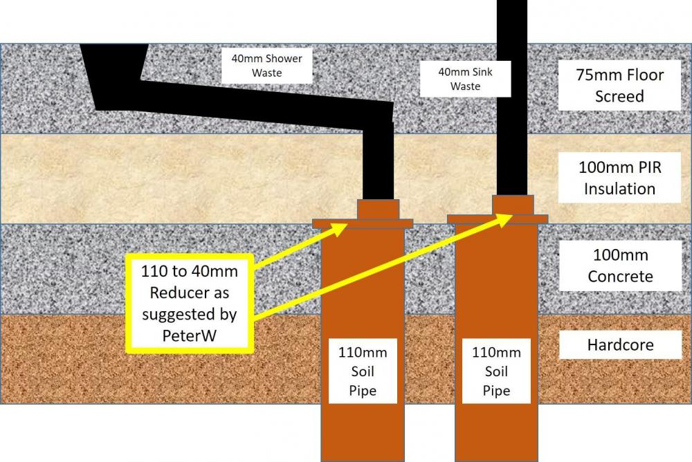
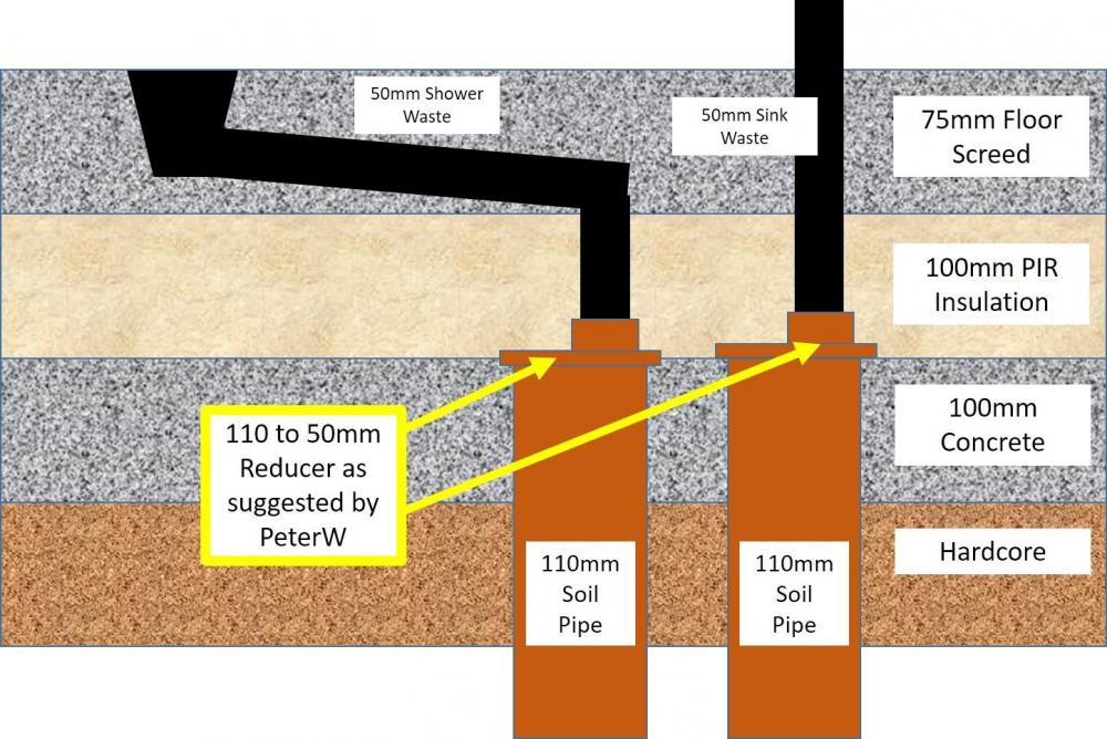
Ok Guys, Please see my crude diagram below and let me know if its ok (its not to scale) My plan is to run the soil pipe up to and level with concrete sub floor - to then add 110mm to 50mm reducers so that the 50mm pipe runs through the PIR insulation and then straight up to the sink and the shower. The shower waste will need to have the screed cut out to fit the waste flush with the floor when the tray is fitted so I intend to take it straight up to start with (so the floor can be laid) then when the floor area is cut out, it can be shortened and the bend added. The length of the pipe from the shower to the soil pipe with only be about 300mm before the bend. Thanks, Wozza.1 point


