Leaderboard
Popular Content
Showing content with the highest reputation on 07/31/20 in all areas
-
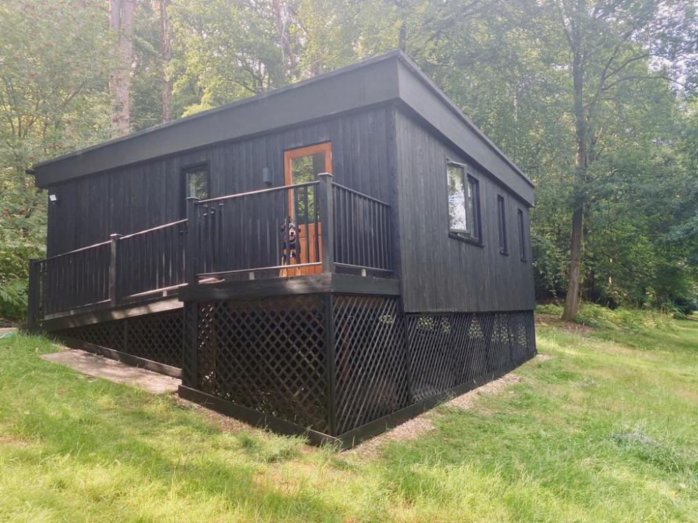
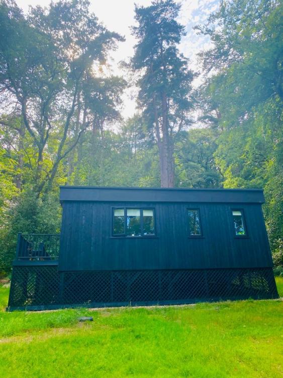
Now this is not the end. It is not even the beginning of the end. but it is, perhaps, the end of the beginning. Coming up on 2 years since we first instructed our architect and over 8 months from submitting our planning application, we have finally been granted permission. It's been a tale of missed bat season, incompetent planning officer, excruciatingly slow conservation officer, numerous complaints and all capped off with some pretty ridiculous pre-construction conditions. But we're there! In the time it's taken us, I've done back to brick renovations on 5 projects plus a couple of loft and rear extensions plus we've had a child and a global pandemic (which I blame on our resident brown long-eared bats) Oh and we've also completed our permitted development outbuilding/yoga studio/stealth shed All I'm hoping for now is to get the foundations in before winter.4 points
-
For all. Here is an old rule of thumb which I have applied to Ian's case. This can be used just to get you a feel for how deep a flat roof joist needs to be. Appolgies for mixing units. Ian.. what about this? if you have enough support and it's a warm roof (insulation on top roughly and thus no ventilation required to the joist void) then run a beam within the roof depth to bridge the bit of the kitchen that juts out. Now you have 26 joists @ 4.4m and 7 @ 1.6m. The beam needs to span roughly 7 x 400 mm = 2.8m so you should manage to get something within the roof joist depth that does not result in the beam downstanding from the ceiling. Based on an actual joist metric thickness of 47mm and a spacing of 600mm (2 feet ) then.. Ian has a 4.4m span domestic roof ~ 14.4 feet. Take the span in feet and divide by two.. 14.4 / 2 = 7.2 inches. Add one inch = 7.2 + 1 = 8.2 inches. Now convert to metric 8.2 x 25.4 = 208mm. Take the next metric size up for a C graded timber = 220mm This is the ball park depth you need for the joists. A common length for a bit of structural timber is 4.8m so it's off the shelf = cheeper than say a longer offered length of 6.1m as they generally need to be cut from bigger trees and so on. You may be able to form the transfer beam from say three 220 x 47 timbers, if that is not enough then you can introduce what is called a flitch beam (two bits of timber with a steel plate between & all bolted together) or if that is still not enough! then a small steel beam. The attraction of this is that all the 4.4m joists will bend and sag over time by roughly the same amount. You are working with solid timbers which a lot of local builders / diy folk are more comfortable with. If you cut a joist too short, nip to the mechants and buy another off the shelf. The connections between the timbers and transfer beam can be done with off the shelf timber hangers too. If a steel beam.. you bolt timbers to the steel I beam web and fix your hangers to these, this avoids trying to fix the joists to the steel directly. Now you have a rough joist size and the concept you can start fine tuning. Watch out for other "non standard" types of load such as snow drifting off a higher roof and so on. You can fine tune stuff by changing the timber grade, closing up the spacing of the joists and so on. Lastly the same old rule of thumb applies to solid joist floors with normal domestic loading at concept design stage but generally you add 2 inches to the depth instead of one. This is an old rule so now we also check explicitly for floor vibration and so on. Once you weigh all this up, the skills of the bulder, practicality, material procurement and so on you may find that solid timbers are the most economic / least risk option? All the best Gus2 points
-
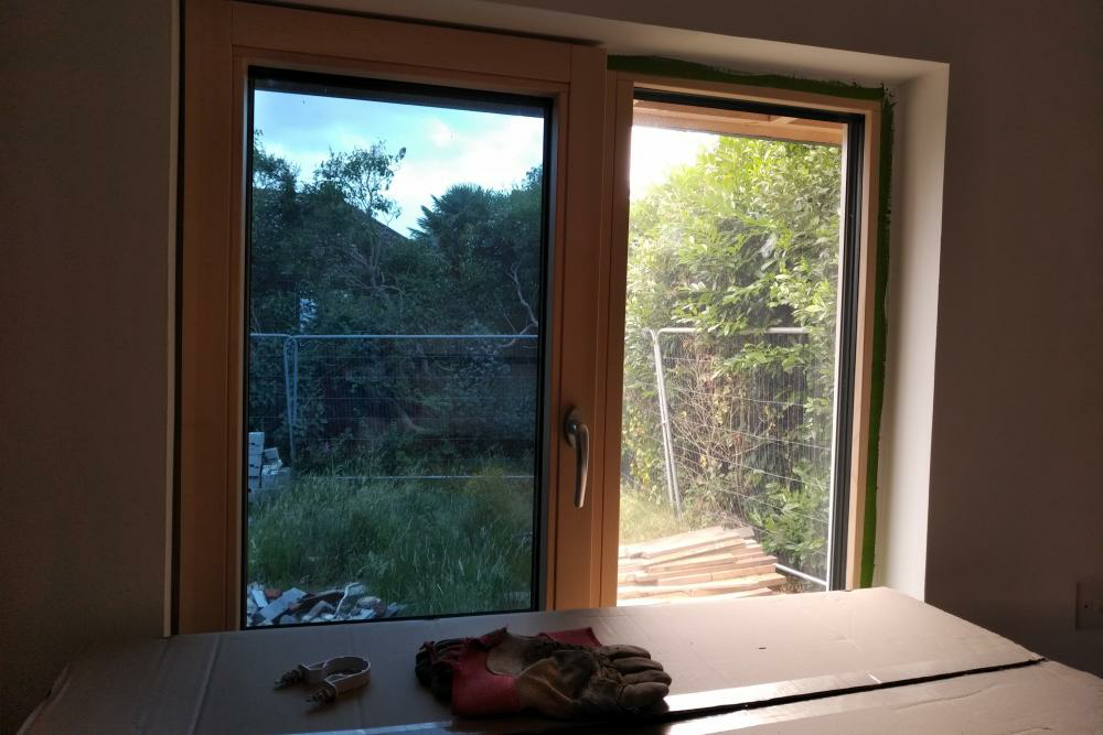
my 60% outboard method also included going over the face of the window frame slightly with EPS. The windows are fine and included a monster 1200 x 2400 3g picture window which is very heavy (I recall installing only too well!) The brackets were/are rock solid, the EWI hasnt moved at all (nor did I expect it to). There are lots of ways to skin this cat, it's a quesiton of what you and your builder feel comfortable with. I've seen the compac foam method - looked neat - battens of compac foam securely bolted to the wall face in line with reveal to provide an insulated outboard structure to fix to and window sits in this. You could also fit a 50mm x 100mm timber batten to the bottom of the reveal to extend the structural sill out 50mm and sit the window partially on that, and use angle brackets to the side. You have to weigh up the stress and complexity of the solution with the gain, Therm models show that the cold bridge is reduced significantly by partially outboarding and even more by fully outboarding. But your renderer will also want a bit of reveal to play with to render in and up to your frame faces so if you have 90mm EWI then you might not get away with going much more than 50mm outboard. remember at this distance you should still be able to sit your window on the structural blockwork and just angle bracket the sides. You can also run metal flat from the side of the window to the side of the internal reveal. I'd also consider running strips of marine ply (12mm) as straight strap from side of window to inside of reveal as well, much reduced cold bridge. If I had my time again I'd use ply strips over metal brackets but my windows were a shade tight to allow a reasonable thickness of ply. Dont lose too much sleep over this detail - the EWI will be a huge improvement, this is marginal gains stuff now though always do what you can where you can do it, and within reasonable cost.2 points
-
+1. Just about to say the same thing. Will make the detailing around the furthest skylight less of a ball-ache too. Flitch beam should be ample, and easy to bring in and man-handle into place piece by piece.1 point
-
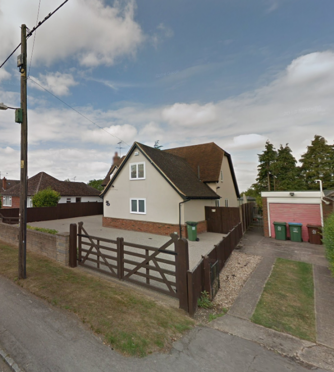
Likely to be a year or two, but it's hard not to see 3 phase making sense given it's all of 4m from the edge of my driveway. 3 phase inverter would pay for itself in no time - Sunny Design reckons it would be a couple of MWh extra exported per year without the 3.9kW limit, and the export limiting kit is something else to wire up and go wrong. There really isn't a lot of price difference between inverter brands, so it makes sense to get a decent one. The other side of things is that we're definitely going to be a 2-car family for a long time to come, and that means we'll have 2 electric cars to charge. 3-phase gives us one phase for each car and another for the house, which should help a lot when time-of-use tariffs become much more common in future. Edit: pink garage on the right is where my electricity meter is at the moment.1 point
-
By the way, I'm not suggesting SageGlass is the right solution for @tanneja, just one that he/she may not have considered. Our requirements were unusual due to the need to avoid having to night purge making SageGlass the perfect (if expensive) solution in our case.1 point
-
1 point
-
Either a double scaffold clip, or buy another lifting sling and just wrap it around the cross-over and it will share the load through the two poles.1 point
-
1 point
-
1 point
-
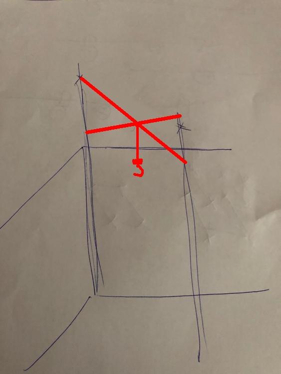
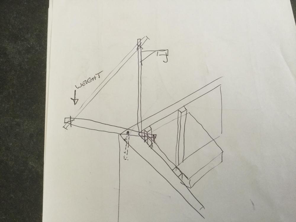
Have a look for a steel stillage, you can get them with solid or mesh floors.https://metalcagesandpallets.co.uk/collections/all/products/metal-steel-mesh-stillage-with-removable-front-shallow-refurbished?variant=31757722026081 I guess the scaffolders call them single clamps. https://www.scaffoldingsupplies.co.uk/products/details/25.html You could also use half clamps to secure to the masonry with Rawl bolts, but you'd need to be cock-on with positioning https://www.scaffoldingsupplies.co.uk/products/details/1318.html Personally I'd leave the other two vertical poles long instead and run the lifting member to them. More stable due to being anchored to blockwork and leaves loading access from two sides The diagonals you show in later drawing will obviously help, but I doubt needed for 150kg1 point
-
1 point
-
My old Dad always said “there is no such thing as right or wrong, only opinion!” Go with what your comfortable with ( I will visit you in hospital with grapes) ?1 point
-
1 point
-
https://sinofirst.en.made-in-china.com/product/BXfQpRdHXcYy/China-Fixed-on-Ground-Hydraulic-Electric-Scissor-Lift-Table.html quite sure if you hunt you will find ligther duty one and smaller table1 point
-
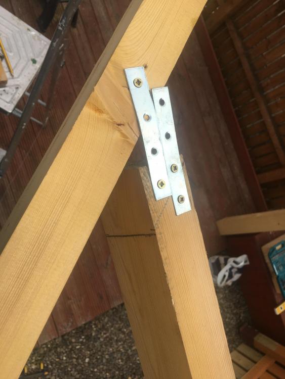
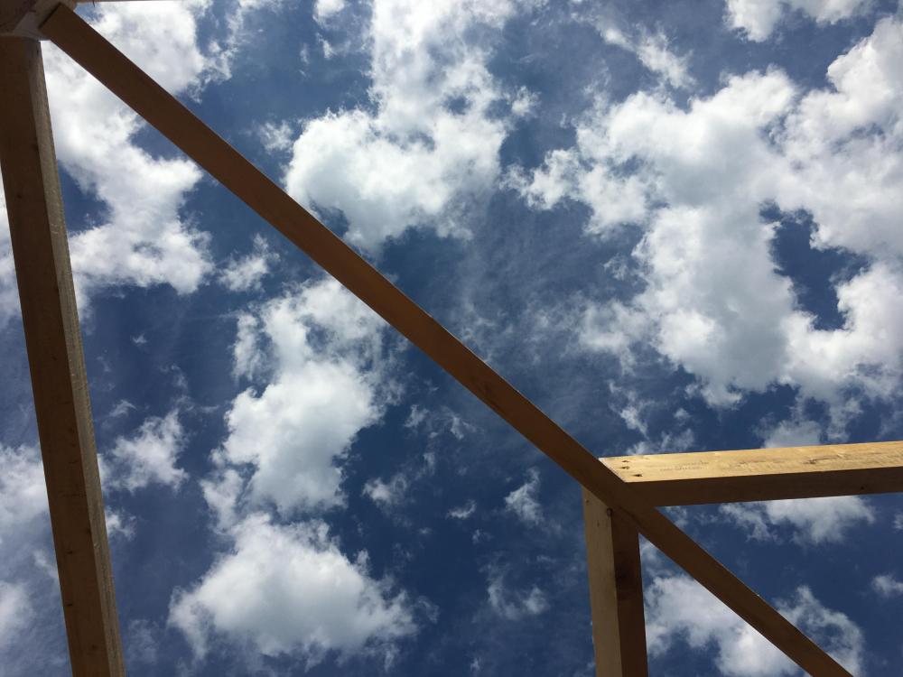
Got a half day off so cracked on in the sun. I offered up the jack rafter, wee plate to hold in place and carefully marked and cut it. Once you’re doing it, it’s much easier to visualise than the videos One of my better joins ? Got the end plate on as it’s getting a mini gutter bingo bango...time for a wash and as it’s Friday Hello lovely1 point
-
1 point
-
I've done a couple of houses with lifts before - the most recent I can think of was about 12k for the lift, it was kind of built in it's own wee room... that was a stannah one, tbf not the prettiest addition to a home I've seen!1 point
-
1 point
-
Another approach is to build a plywood box out into the insulation layer mounted on the wall, like a deep picture frame and mounting the windows in those. F1 point
-
1 point
-
I don't think there will be many brackets available online for this, majority are custom made and welded on-site, or by a steel fabricator. There is also as you mention the compactfoam, i've never seen this product but there are videos on youtube showing it being used for windows, so it must be pretty strong. With regards to airtightness, as long as you have a flexible airtight tape from window frame to masonry, there shouldn't be any issues with slight movement. If you don't hang the window right out, there will always be a thermal bridge, as you say will have 30mm EPS on it, but still a lot less than the rest of the building. Personally I'm keeping my windows where they are, and doing a return, and then using insulated plasterboard on the reveals internally to compensate.1 point
-
As an off the shelf thought, I have a design in my head to make a DIY lift that operates over a staircase and something I will build if the need ever arises. It's not something that would meet with any approvals whatsoever though.1 point
-
Is the existing concrete base the correct size for your new office? If so simply lay a course of thermalite block around the perimeter, cutting them at around 70mm thick as a thermal break. Bed these down in 15-20mm of cement and tap down accordingly to get a nice straight ( flat and level ) top edge using the cement taking up any undulation. Use that then as an insulated footer for the stud walls with the thermalite blocks providing at least some thermal break. Then you can blind the remaining slab surface with sharp sand and lay 50mm or 75mm of EPS ( polystyrene ) insulation directly onto the slab. Put two layers of 18mm OSB3 atop the insulation, with the second layer perpendicular to the first and you'll then have a nice start point to get the stud frame walls up and have a pretty decent separation from the cold of mother earth. DPM goes over the thermalite and the EPS to make the damp barrier, so try to match that level as best you can by deciding on the thickness of insulation you desire and then cutting the thermalite blocks to suit. Leave the DPM overhang the thermalite by a good 150mm and then clad over it when sheathing the outside walls with your chosen rain barrier to keep it down-turned over the thermalite ( as that will attempt to bridge damp up / outward so cannot touch anything porous ). I've done a few 'garage conversions' with this method, and the double layer of OSB ( tongue and groove 2400x600mm sheets ) over the loose insulation feels rock solid underfoot. You will deffo need to blind the slab with sharp sand first ( after laying the perimeter blocks ) and get that nice and uniform for this to have little / no 'wobble' possible. Invest some time there as it'll pay dividends later on 3x2" timber at 400mm centres vertically for stud walls, with 25mm EPS across the whole of the internal walls and then screw 11mm OSB3 through the EPS and into the studs for final internal finish. Looks fine when painted, but you could plasterboard if you need a 'posh' finish. Monopitch roof is a doddle, and again, just timber for simplicity. Make the walls all level and fit some furring pieces on top to create a downward slope, from front to back, so the guttering is at the rear. 6x2 pearlings at 600mm centres atop the furring pieces, from left to right as you look at the front, and 18mm OSB3 atop the pearlings and whatever you want on top of that ( EDPM / felt / GRP etc ) but beware metal sheets as I found the rain made it nigh on impossible to have a conversation when it was lashing down. Solution will be; acoustic insulation and SB plasterboard most prob, but will be a job for a rainy day Depending upon your choice of roof material you can just get away with insulating the roof void with cheap attic roll in the depth of the 6x2"s and covering with green plasterboard.1 point
-
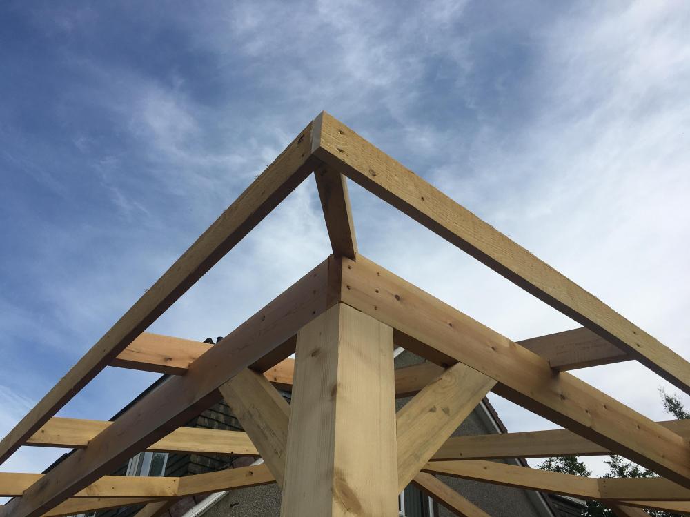
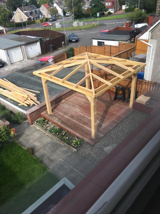
Check it doesn't need planning permission first. Eg within 2m of the boundary the eaves need to be <3m high to come within permitted development rules. However I think that's measured at the point furthest from your rear wall. Details in here.. https://www.gov.uk/government/publications/permitted-development-rights-for-householders-technical-guidance Those dimensions sound ok to me. For the brackets I would use something like this that raises the bottom of the posts off the ground a bit. https://go.twenga.co.uk/to?s=9720237&gap=&gat=pla&aagid=48884992022&acid=1017976262&atid=pla-405564714126&aadid=247473114207&mcoid=114135292651&appid=405564714126&gd=t&mcid=166725238&url=https%3A%2F%2Frover.ebay.com%2Frover%2F1%2F710-53481-19255-0%2F1%3Fff3%3D4%26pub%3D5574631662%26toolid%3D10001%26campid%3D5338624526%26customid%3D%26mpre%3Dhttps%3A%2F%2Fwww.ebay.co.uk%2Fitm%2FHeavy-Duty-Galvanised-Concealed-Fence-Gazebo-Post-Support-Base-Bracket-Shoe-%2F114135292651%3Fvar%3D&gclid=CjwKCAjw34n5BRA9EiwA2u9k37T3KqGX8p8ITrqewKeFRaJagIVu38y1rLaNeymfLDUqZ3arwX3BexoCJbQQAvD_B If using pressure treated timber I'd cut the post to height and put the cut end at the top where its sheltered under the roof leaving the deeply pressure treated end at the bottom. Obviously treat the cut end but I reckon it will last longer if you do it that way up.1 point
-
the metal web ones we had put in at 600mm centres I wish we had put them at 400mm centres...... I like a nice solid floor.1 point
-
Don’t forget that some BMs use smaller 4 wheel wagons when they know there is an access issue. My preferred one has 2 types - I know to request the smaller one if I need a tight space delivery.1 point
-
I have to take 3 bins 300m down our drive, I intend making a small trailer that the bins will live on that can be towed by the ride on mower.1 point
-
My present car (bought second hand) came with a towbar that looked unused, but no towing electrics. Apparently it was fitted just to tow the wheelie bin to the end of the drive once a week.1 point
-
Thinking about your step counter, perhaps you could design in a pulley system for your trolley whereby you attach a post box or a bin to it and haul it in ? Heavy bins are no fun. We are, probably, about 15 metres from roadside where our postbox is and that is annoying enough. There is also a security risk. We have had parcels stolen.1 point
-
You can PIR in any thickness well, beyond 70mm up to and including say 150mm or even 200mm. eg Celotex to 200mm https://www.celotex.co.uk/assets/handy-guide_nov18.pdf The insulation material is a relatively small amount of the cost, and my advice is to really work on the detail and ask lots of questions. I have looked over the years at EWI on half a dozen different houses and always ended up doing IWI, underfloor insulation and loft insulation instead. That is probably not what you want to hear, but you will need to be doing the project on the basis of comfort as well as economics. Happy to comment and point you to resources. Ferdinand1 point
-
0 points
-
0 points
-
I did think that type of arrangement is what you meant. But I'm more comfortable ( i.e. less chance of my death ) with 4 corner posts I can then stick scaf boards across as a 'loading' platform. Also I'm unhappy ( not as in sad, I've drunk some wine now ) with the counter leaver weight. A corner to opposing corner vertical with a horizontal gantry across means the weight of the lift load is central so doesn't need a counter balance ( if I'm wrong I'll die proving you were right )!0 points
-
0 points
-
0 points


