Leaderboard
Popular Content
Showing content with the highest reputation on 12/13/23 in all areas
-
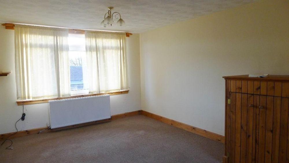
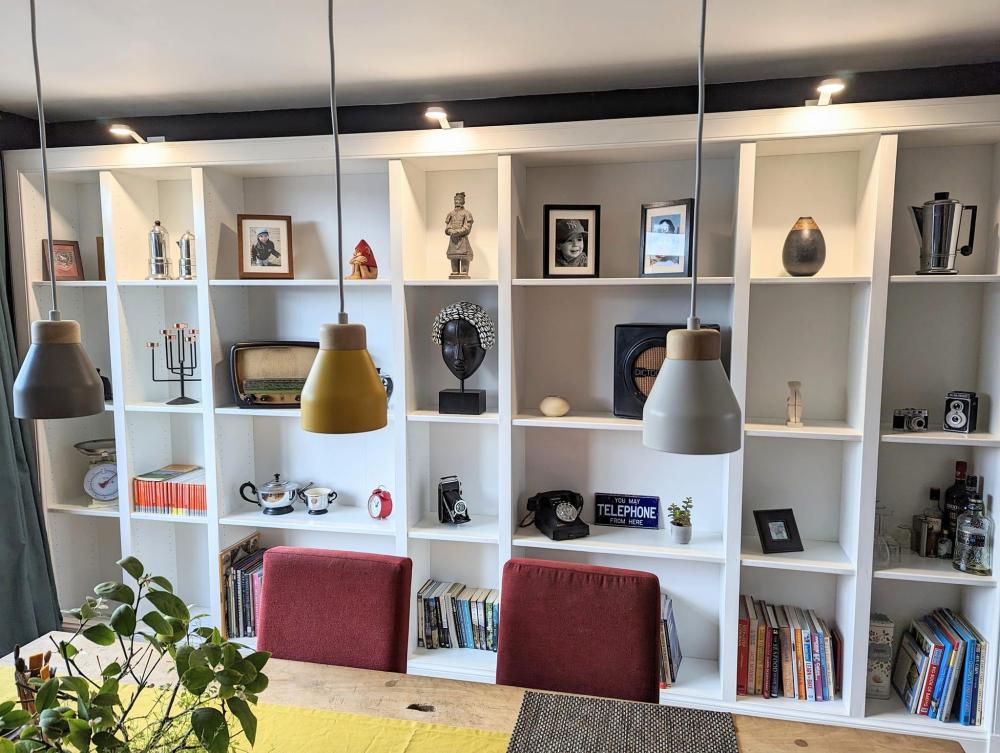
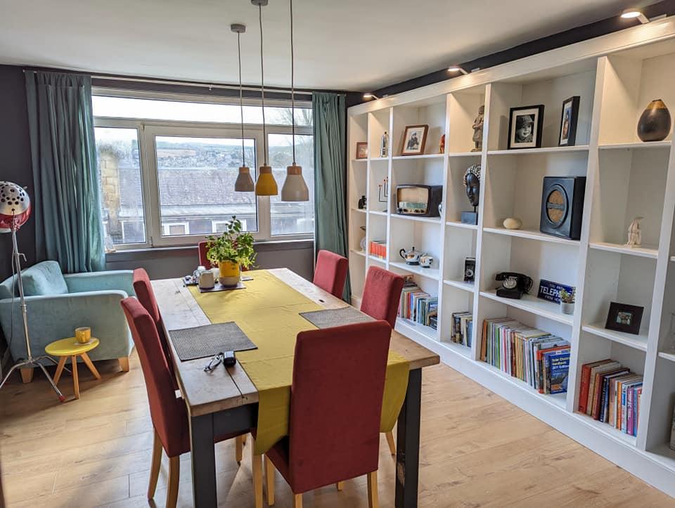
I thought I would post a pic of a Billy bookcase hack that I finished recently in case it is of interest to anyone. The total cost was under £500 - £200 for the bookcases, then architrave, skirting, paint, facing strips, lights, caulk etc came to a bit under £300. Billy's are pretty ugly on their own, but if you cover the edges up with proper wood then they don't look so bad. If I was doing this for my forever home I would use a solid wood bookcase like a Hemnes instead. The first job was to figure out how to get the bookcases to completely fill the wall recess that I wanted them to go in. This involved calculating how wide the spaces between the bookcases needed to be to work with the available Billy sizes, which are 400mm and 800mm wide. A lot of this was dictated by what facing stripwood I could get straight off the shelf without having to rip it down along the full length. It was a lot of headscratching and I had to make a spreadsheet in the end to figure it all out. I then moved the electrical socket outlet that was on that wall to the top of the bookcase so that it could be accessed after the bookcases were fitted. I made up all the bookcases, screwing the shelves through from the sides and back to keep them from bending. This will mean they can't be moved about but I am fine with that. Billy's often look bad because the shelves go bendy and I wanted to avoid that. I then took my time levelling the bookcases on a base of CLS framework, then screwed the bookcase units together with spacing strips in between so that the facing strips which covered the edges of the Billy's were the exact right width without needing cut down. The whole unit was secured to the wall with angle brackets. I fitted CLS right around the outer edge of the bookcase unit to give the architrave something to fix to. I then cut strips to cover the front of the shelves and painted those, along with the vertical edge facing strips, architrave and skirting and then fitted them all. I did start filling in the unneeded shelf support holes with caulk, but it was a massive faff and didn't make it look that much better so I gave up on that. The lights were bathroom cabinet lights out of the B&Q bargain bin for £3 each but were much too cold with fixed leds, so I bought a piece of theatre lighting gel in orange for a couple of quid and cut wee discs to fit into the lights to warm them up. The lights are wired together and plug into a smart plug that is powered from the relocated socket at the top of the bookcase. You can't see it behind the architrave and the lights can be turned on by telling Google to 'turn the bookcase lights on'. A good party trick. Here's the finished article, with the 'before' pic at the bottom for context. I'm pretty pleased with it, given the cost. The edge facing strips give the impression that it has been made with solid chunky timber and the round edge shelf cover strips also hide the fact it is made with particleboard. I've done a wee bit of other decorating in the room too. 😉6 points
-
When the house was built, I asked the builders to put some shelves in the hall cupboard. They put in some unpainted MDF and we have always felt it looked a bit cheap compared to the rest of the house. Having watched how easily a DIY-Kitchens Kitchen went into my brother's flat I decided that I would order up similar for the cloak cupboard. DIY-Kitchens did not offer enough customisation options, but they are very good value. I priced it up with a company called Lark and Lark who offer more options for carcas colours and custom sizes, but they wanted £400 extra on top of their normal delivery charge to deliver to Scotland. I then went to DIYHomefit who supplied our dressing room which was installed by the builders. I measured, measured and measured again, then ordered the stuff. Came in at £1700 including VAT and delivery which was more than I was planning to spend. Probably saved a good £1000 by installing it myself. I started ripping out the old stuff at 10am yesterday and finished installing all the cupboards this evening. I have filled the holes and will paint and install hanging rails tomorrow. I was really surprised how smoothly it all went. I had installed a utility room years ago, but it was very simple with no infil panels to cut. That was the scariest bit, but it went pretty smoothly. I now have plans to do cabinets around our home cinema screen in the new year.4 points
-
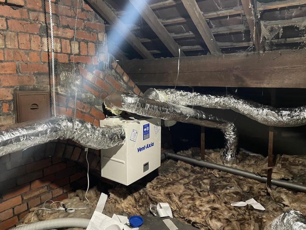
I DIY fitted a MVHR. It works really, really well, however do not under estimate the work in installing. We went from a house that had mould in the bathrooms (no extractor fans) to much better air quality. Running the ducts in the loft was the easiest, for a given value of easy in the loft. Running ducts down to the ground floor took a while as hiding ducting in cupboards and also ensuring the loft end worked was more effort. Fitting the intake/extract vents in the roof was straightforward for a roofer! It took five weekends; One for the intake/extract/condensate drain/unit setup. One for the upstairs rooms (two bathrooms, three bedrooms). Another for an extension bedroom (should have hired a core drill for going through an outside wall that is now internal). Another for downstairs ducts to kitchen and lounge. Another for a downstairs loo that involved dropping part of the ceiling to fit the ceiling duct as I could not access above it. I think I could do it in half the time or less as now more confident. All my parts came from ebay, isells, BPC, Screwfix. I did the design myself with a spreadsheet of room volumes and flow rates. I went slightly below the suggested flow rates for "Normal" rates and over for Boost. I overspeced the ducting to reduce noise (ie twin ducts to all rooms as running these is not much work relatively). I fitted noise silencers. I would go higher for boost, to clear damp air quickly, however above 90% flow rate it is noticeable noisy. We have virtually zero condensation. The odd, tiny bit behind some plantation shutters on some cold nights. Some condensation on a door lock that is a cold bridge in a yet to be vented room (its the hardest to get to) and sometimes on the letterbox flap (needs more insulation!). If you have reasonable loft access and only need to do runs in the loft this will help reduce install effort allot. I assume you could have the intake/exhaust through a gable end which should be quite easy (given value of easy). Think of the condensate drain and where that goes (I suggest a soil vent spigot to keep it warmish). It is great, but allot of work. I would have a strong think of doing it again, but on balance would do it again. I did consider four individual room MVHR as these would be quite allot of work to install (core drilling, running electrical feeds) and these are expensive units. I think this would be cost neutral compared to my MVHR. Maybe slightly less work, but not much. Running costs would be more due to more fans. It would not have improved the air in non-vented rooms compared to MVHR. Your air leaks might be an issue although depending on units you can set them to run intake fans faster than extract to positively pressure the house which will help with internal air quality. This would be slightly less efficient as you are losing air that is not going via the heat exchanger. On either method consider the filters the units have. Mine goes upto M5 (A "Pollen filter" ie 50% of Pm10). Newer models have HEPA level filters. You could DIY a HEPA filter on the intake from BPC/Isells bits. Sorry that turned into an essay...3 points
-
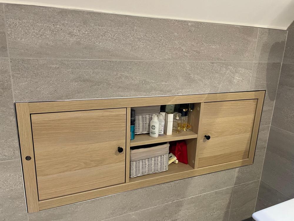
This is my Kallax IKEA hack. It's a 4x1 Kallax shelf, cut down to 3x1 (more difficult than it sounds), and then 90mm cut off the back to make it fit in the void in our sloping roof. Works very well - 5 years daily use and it's still as fresh as a daisy. The small round thing on the left hand side is not a camera (!) but a light sensor for our LED floor flood light. For night time visits...2 points
-
2 points
-
https://givenergy.co.uk/breaking-uk-government-announces-tax-relief-on-battery-storage-systems/ Looks like the stars may have aligned for me.1 point
-
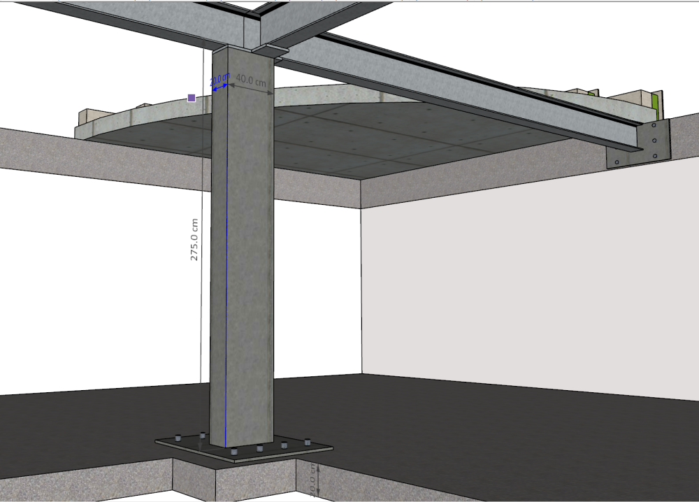
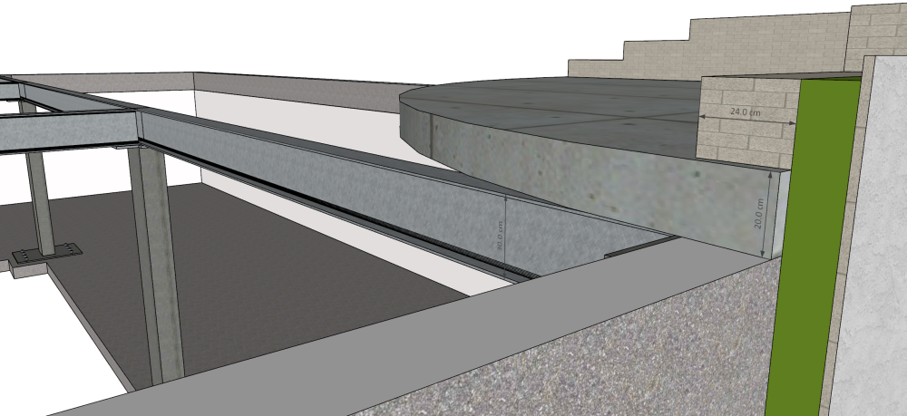
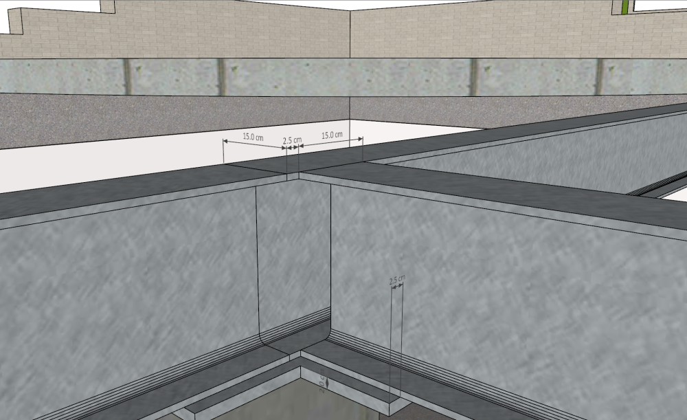
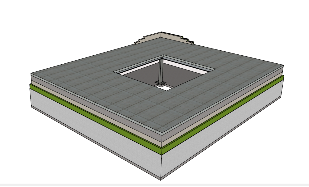
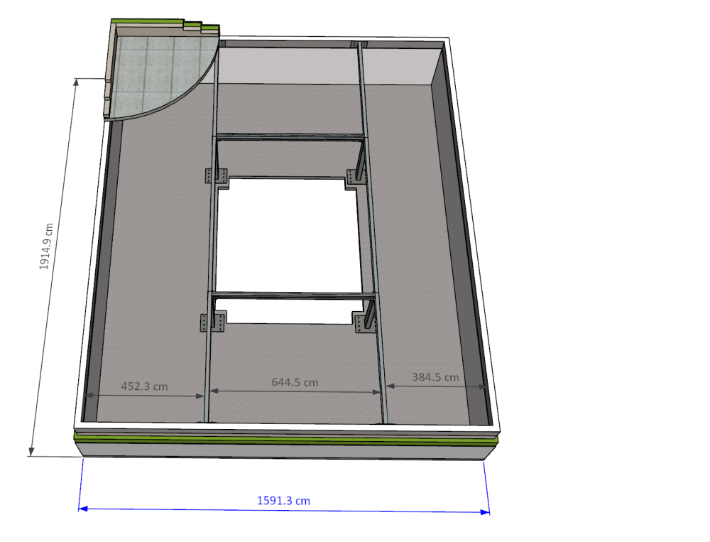
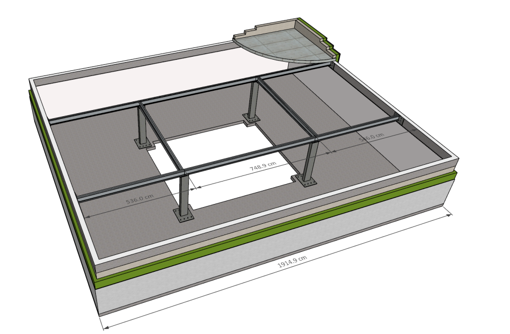
Hello, I'm in the design phase of my retirement home. Briefly, this will be a single storey home on a reinforced concrete slab foundation. The house footprint is approximately 20m x 16m with a central 7.7m x 6.5m atrium glazed on 3 sides and topped by a glazed roof. Perimeter walls are structural 24cm AAC with external insulation, VRB and render. Roof slab is 20cm 2% reinforced concrete extending from the perimeter up to the 4 sides of the atrium (meaning the roof slab has an area of approximately 270 m2, volume of 54m3, and weight of approximately 135 tonnes). The roof slab is supported above a suspended gypsum board ceiling by a framework of steel beams that are welded to one another and bolted to the perimeter walls into a reinforced concrete sub-roof transition zone poured on top of the AAC. Roof slab will be poured out to the perimeter of the building and will be clad (along with the sub-roof transition zone) with more efficient insulation than the insulation cladding of the AAC so as to provide a uniform u-value and flat vertical facade. AAC block will be laid above the roof slab for an additional 60cm for the parapet. The steel beams will be supported by rectangular hollow steel columns welded to base plates that are bolted to the foundation slab. My question concerns the steel beams and columns for my design. I'd appreciate some feedback of my initial sense of the size of beams and columns I will need. The beam assembly consists of two long spans running down the sides of the long axis of the atrium that are joined by two shorter spans traversing along the shorter sides of the atrium. To simplify transport and installation, each of the two 20m long spans will be composed of 3 shorter beams welded to one another to make up the 20m length. The two shorter beams traversing the 6.5m sides of the atrium will be welded to the 20m spans. All beam intersections (those where the 6.5m beams meet perpendicularly with the 20m spans, as well as those to join the 3 beams into a single 20m beam), are located above the 4 corners of the atrium and are supported by 4 RHS columns with top plates providing substrate for welded connections of the beams. Apart from the roof/parapet construction weight other components of static loading will be a fairly extensive photovoltaic array and solar thermal water. There is not a requirement for heavy snow loads etc. Based on my research I am designing with the following sizes in mind: IPE 300 for all beams and 200x400mm RHS sections for the four columns. I realise I will need to engage an architect and SE eventually but before I make this contact I want to have a good sense of the general dimensions I will likely need now since this has knock on effects for other elements of the design. Do these specifications sound like I am generally in the right neighbourhood in terms of overall dimensions for my beams and columns? Appreciate any advice from fellow builders here.1 point
-
There are no taps in the bath. This is the only thing in the bath: the waste with intergrated filler.1 point
-
I balanced mine up with the aid of an anemometer bought off ebay, a plastic bucket with a hole cut in the bottom and a sponge seal around the top. I had to add a speed controller to one of the fans as it was more powerful than the other. I wasn't too difficult. I've got some mods to do so I'll be doing it all again soon.1 point
-
I have a condensate trap (as a collar) on the extract pipe just above the mvhr and another hole at the bottom of the unit. Hope it helps..1 point
-
Amazing, thanks all for the speedy feedback. Saves me having to rip up the slates we put on in the summer for an SVP! Great point about using the side boss on the T - I'll let you know how I get on1 point
-
Hello there ash. Happy to have a quick chat with you on the phone if only to reassure. You can pm me or give me a Pm for my number, you'll find me on the internet also. I'm based near Glasgow. I hope so! Agree. It's ok to have a quick chat to understand the background but not ok to judge others / criticise their design without letting them know you have been asked to formally review under instruction from the Client. It's not professional and also basically unfair. It's not a big thing.. my designs get reviewed / checked all the time usually by an in house Council Engineer (or they contract out for checking SE services) on domestic projects, on say bigger industrial stuff ( I often work for the Contractor) by the Clients own Consulting SE. It could well be that the Architect, maybe you, did not fullly communicate to the SE what structural envelope was available to them to fit "their stuff into" and they did their best to fix it at a reasonable build cost vs intrusion into the Architectural space? It may be that the Architect did their best to achieve compliance with the building regs and maybe just did not know about these "structural bits" as they are not SE's?1 point
-
This is what happened the last time I pumped the old soldier on camera. https://metro.co.uk/2014/02/06/bus-submerged-by-sea-foam-during-storms-4294125/1 point
-
1 point
-
1 point
-
That sucks. For once it looks like I’ll benefit from my endless prevarication.1 point
-
I’ve put window film on it in one of rooms, it helps but isn’t a wonder product. I’ve just DIY’d an MVHR install in my 30’s semi. It’s made a huge difference in air quality. It’s no longer stuffy, there’s no condensation on any windows as we used to have humidity 65-80% regularly. I feel I sleep better with the fresher air in the house which is something I didn’t expect. Also my partner hasn’t used her inhaler since we fired it up, but that be coincidence. All in all, I’m super happy with it but it was loads of work! I’ve now fully insulated the unit (photo taken before) and has helped a lot with warmer supply air. I can recommend MVHR.1 point
-
I would be more interested in the install, a well installed system and mediocre heat pump, will always out perform a mediocre install and fantastic heat pump. Both are good makes, what else has been quoted. Are you an open single zone system or zones everywhere? Buffer or no buffer? UFH, radiators or a mix? Viessmann tend to take the whole system approach and it's done the German way, so will come weather compensation out the box, usually well set setup. You never here them mentioned on here, maybe for a good reason.1 point
-
1 point
-
We did something similar. The first time, we laid the wallplate on the poured concrete, this time we simply got the level and them secured the wallplate using resin bolts. As you can wee, we'd left enough ICF to be trimmed down flush to the top of the joists, then when the OSB went on, we used air tight foam, as well as between the joists and the ICF.1 point
-
1 point
-
1 point
-
1 point
-
Good case for timber frame with block outer skin.1 point
-
Yes definitely worth it if you're planning running Frigate, saves masses of watts to offload image detection from the main CPU Thankfully USB version available again now. I got mine during the post pandemic chip shortages , and the PCIe format limits how and where I can run it.1 point
-
>>> Have zero faith in the SE It may be that the architect overlooked the engineering requirements or didn't think them though. Go back to the SE and ask if there's any other solution. Again, the SE may not have twigged your requirements accurately re look or function and/or assumed that you want the lowest cost solution. There may be other solutions (there often are) which will accomplish both the look, the functional requirements that you have, and the the engineering. A good SE will usually be happy to try and meet all three if they can. Of course, there are sometimes cost and engineering requirements which can't be overcome or only at extreme cost. There was a Grand Design last night where the roof was a bunch of different angles and facets. Fine, it wasn't so crazy that it couldn't be made by actual contractors (although a bit of a bodge in places - the SIPs people were using a sledgehammer and a sabre saw to 'adjust' their work) but it was substantially more expensive. p.s. alternatively define what you want exactly in terms of function and look and feel and point the SE & architect at each other and ask them to come up with a solution. Sometimes they will be able to sort everything a a 5 minute call (or have a 3-way call). That avoids you being the Chinese whispers guy.1 point
-
Downside of this is an earth leak (especially likely on an outdoor circuit, but easy when changing a lightbulb indoors too) will trip all lights in the house. Sparky on my current project wants 2 RCBOs per floor to ensure everywhere still has some lighting even in the case of nuisance trips. I think we're up to 12 RCBOs in the Loxone cab, and about 30 more in the main 3ph DB1 point
-
Me or Gus. Gus is Scottish I believe , so judging by your username he's probably best placed... although the laws of physics remain constant. Although there's always another structural solution, engineers will tend to go for the most economic solution either in simplicity/buildability, materials or time. If you or the architect hadn't given them a clear constraint then they may well not have appreciated the importance of the beam positioning. (Also any opinion we give is only in general terms, if an engineer comments specifically on a project then really they should be engaged and make contact with the original engineer.)1 point
-
Anywhere between L/18 to L/24 would be fine for a first stab. It really is just as an estimate to avoid an architect leaving 100mm void for a 5m opening. If supporting external walls etc then L/18 is the better end but there's always the get out of heavier weight or UCs.1 point
-
You could use some cladding boards with the star shape cut out of multiple https://www.cedral.world/en-gb/cladding/our-products/cedral-click/ These are pre painted and would not need to be treated. It's even possible that the raw cut inside the star would actually look quite attractive The super-cheap alternative would be some suitably painted concrete board like an aquaboard offcut Regards Tet1 point
-
@George My SE boss taught me to use L/18 as the first stab. That is safer in ensuring enough space is allowed for an economic beam. This was in the days of number crunching, so being close with the first assumption saved a lot of iterating. Perhaps Euro sizes can be shallower, but if anything they are skinnier. Please tell me if 1/18 is no longer correct and I'll change my general advice.1 point
-
Thanks everyone. Re Roman inspired stonework that's not really the aesthetic I am going for here. I'm a fan of the Japanese aesthetic and this atrium is inspired by the central courtyards and atria you see in Japanese homes. This is a departure all the same, as it will be sided on it's north south and west sides by full width sliding glazing between the columns. The east wall will be solid as that gives on to bedrooms. The house entrance is on the north facade (top of these drawings), and a good percentage of the south facade is glazed so on entering the home one should be able to see through the atrium out into the back. George thank you for your L/24 rule of thumb - do I use the entire combined span or only the longest spans between columns as my L? Also take your point about the RC roof slab - AAC slabs are available up to 6m in length and those would be significantly lighter as well. I have given some thought to that but want some spans that are just a bit over the 6m...your line of thinking re hollow core and prescast sound like a much more appropriate direction.1 point
-
1 point
-
Interesting design If you want a rough estimate of a beam depth use the ratio L/24 (L is the span, same unit for the beam depth, rounded up to.ansection designation - this is very rough and ready but is the only structural calculation I'll let an architect do). RC roof slab will be very expensive because falsework mobilisation costs will add up. Hollow core or just precast planks with a structural topping, or just composite decking, would be better.1 point
-
1 point
-
1 point
-
The beams will be about 400mm deep. To minimise intrusion to the room, the joists can be inset. What will the atrium walls ( and external walls) be made of? It's good to see you enjoying the development of the design. I'd say work out the room layout and then get an SE.1 point
-
You are wasting your energy focusing on section sizes. Get a design and layout that works for you and will be acceptable to the planners. Get a good structural engineer to design the foundations and structure. Make sure you plan for decent airtightness and insulation.1 point
-
Self build for as much of it as is reasonable. I'll of course bring in specialized trades when I need to - e.g. the steel framing etc. I've certainly thought through the other issues you mention but at this stage I want a sense of whether I am working with a viable starting point in terms of the building envelope. If this is basically in about the right place in terms of sizing, then I've got a quite detailed set of sketchup plans laying out the living areas of the house. If I am overlooking something, or should be incorporating significantly different structural support dimensions I'd like to know about that early on. And again, I will of course be engaging an architect and SE etc. but just want to have a sense of this now.1 point
-
Is this a self build home or a design project? When designing a home it’s al about the rooms, spaces, light, livability etc. not the structure detail.1 point
-
1 point
-
1 point
-
Thanks for the fast responses. I didn't describe the design as well as I could have - although GavH seems to have pretty much got it. It's essentially 4 volumes distributed around the atrium. Picture is worth a thousand words so here are a few quick sketchup captures that hopefully give a better sense of the design.1 point
-
SE, mainly because your design could be completely wrong and you'll be wasting a lot of time and energy. I'm an civil/ environmental engineer but not structural, and my preconceptions and design ideas were blown out of the water by what the actual SE came up with. And an SE isn't going to want on site welding.1 point
-
Took me a little time to get my head around what you are proposing. The max wide of the building span is 20m, however due to the 4 columns providing the Atrium corners you only had to deal with a maximum unsupported span of 7.7m. You will also have to consider how the beam will produce substantial point loading on your external walls and may required additional columns at the outer wall ends of each beams too. This is more that some structural Calc's you need an engineer to be involved on it from day one.1 point
-
In my minds eye I see a horizontal "picture frame" 20m x 6.5m with a post on each corner. I can't however see how each splice in the 20m beams will also be located over the corners of the atrium. This will need scoping by an engineer because there is so much here that can't be done easily on a domestic scale. No snow load? is this in Dubai?1 point
-
In a way it makes sense to have a stab at the beam depth to see if the geometry of the house works at all. So here is my advice. A 20m spanning beam is impractical, and would be very deep. Perhaps over 1m. More likely a complete portal frame of 2 columns and a beam. Try that. Then revert to getting professionals in sooner rather than later. Why do you need a 20m clear space?1 point
-
SE first, wind loads, live loads, connections, torsional loads have more effect than the mass of a structure1 point
-
@Mikey Our builders used https://www.originarchitectural.co.uk/. They supply also sorts of fittings and also did the calc for him I think..1 point
-
I have another thread in the new build design section detailing the journey to get the plans finalised and submitted. In the meantime, have been reading up about how to actually build and also attended the NSBRC show over the weekend and took in their talks/seminars (quite useful for a beginner). So far, I have no preference for a particular method of building apart from wanting what everyone wants - super speed and super cheap, with a top quality finish(!) I've listed out the pros and cons of each to try and understand the differences between the three methods: Traditional masonry - Pros 1. Cheap parts and easy to get insurance/mortgages 2. Easy to DIY in the future Traditional masonry - Cons 1. Slow to build 2. Labour in London is expensive (£500 for a brickie apparently) so cheap parts are offset by the long time it takes to build and get water/airtight. Timber frame - Pros 1. Quick to build when on site as all the design is done prior and built in a factory 2. Can find companies to do foundation slab and erect structure - which is the hardest part of the build. 3. Great insulation and thermal efficiency Timer frame - Cons 1. Used to be about 10-15% more expensive pre-COVID, and this has only got worse with timber prices shooting through the roof. 2. Slightly harder to get insurance/mortgages but this is the dominant method of new builds now apparently. 3. Noise issues are greater in a timber framed house? ICF - Pros 1. DIY element of laying out blocks, meaning some labour costs can be saved. 2. Monolithic structure means efficient house, and a feeling of being much more solid as compared to Timber frame. 3. Less noise issues - especially if paired with a block and beam floor. 4. Used to be relatively expensive - but now very competitive as concrete costs haven't gone up as much as timber in the last 2 years! ICF Cons 1. DIY options will become limited in the future as cutting through concrete isn't fun 2. Waterproofing external insulation is key - though not impossible. 3. As with TF - harder to get insurance/mortgages as this is less popular but now growing. All in all, I'm leaning towards ICF now as having a concrete structure and combination of beam and block floors will get rid of my biggest bugbear - the noise issues in old housing stock. Hate hate hate creaky floorboards and sound travelling through the house when you drop something relatively light. Thoughts greatly appreciated. Cost is obviously a concern though all conversations point to each system roughly equating to about the same in the end - higher part costs are offset with quicker build times (and lower labour costs).1 point


