Gus Potter
-
Posts
2339 -
Joined
-
Last visited
-
Days Won
29
Everything posted by Gus Potter
-
Selecting DHW cylinder for ASHP + solar thermal
Gus Potter replied to muhrix's topic in Introduce Yourself
Hiya muhrix. You'll find lots of different takes on BH.. the great thing about BH I find is that you get loads of ideas, food for thought and friendly support. To get the best out of BH, just keep asking questions. But try if you can to provide some detail on your particular circumstances. This way you'll get the best feedback. I'm definitly not an expert on ASHPs compared with some of the other members of BH! -
Selecting DHW cylinder for ASHP + solar thermal
Gus Potter replied to muhrix's topic in Introduce Yourself
I'm a bit of a philstine.. My sister lives on Tiree. She has a big house used as a B&B with lots of demand on the UF heating and hot water. The house is served by twin ASHPs all facing the prevailing wind which pretty much blows all the time. Temperatures rarely drop to a level ( say below -4.0 deg C) where the pumps really need to work / think hard. They cycle fine on the defost mode and so on. They also have a big water cylinder and the controls are pretty simple. Any excess heat energy is contained within the building envelope any way so it's trapped inside the building. Have a look at what is outside your house, sheltering effects from the wind and so on.. think / start / review from the basics.. is the location right? Am I going to get good air flow outside without the fans having to work too hard? It's easy to neglect this. Often you can't see the woods for the trees.. you know you want one but don't carry out a full review of your design.. often because you don't want bad news. The design of ASHP's is an iterative process just like Architectural Design. Yes the tank (Tiree) may be over sized and the controls simple but when you look at the long term costs in terms of maintenance it's a no brainer. If you have the environment in mind remember that if you make your system complex every year at least one part is going to go faulty.. person in a van to fix..plus often top up of inhibitor.. parts will fail just before or during the xmas period so you'll get no points here. Look the simple stupid option, some times it's cheeper / more practical in the long term to over size say the HWC but keep the works inside simple. Keep the controls as simple as you can. Yes it's tempting to get carried away at this stage but once the novelty has worn off and you get back to normal life or want to sell the house on.. imagine trying to explain to a prospective buyer how the system works! I would go back and force yourself to look at how simple and stupid you can make this. Compare the costs over the long term then take a view on what suits yourself.- 25 replies
-
- 1
-

-
- ashp
- solar thermal
- (and 2 more)
-
After 7 years ; moving in ….
Gus Potter replied to Pocster's topic in General Self Build & DIY Discussion
Fantastic news. Always have enjoyed reading your posts. Look forward to season 2. Have you considered updating your avitar to reflect.. you have finished / reached practical completion. Is season two the snagging? or do you have something else in mind? -
Hi Jilly. Looks like you are really making progress... remember your posts about protecting steelwork.. Can you set up your LPG system based on you getting an ASHP later. Yes buy the LPG combi boiler but set it up to emulate an ASHP although temporarily running at a higher temperature. You can get a cheep boiler to see you through to the next stage, a regulator and a couple of 47kg bottles. Make sure you get it serviced.. may be able to sell on later second hand to another BH member? In the grand scheme you have taken a lot of time /care to insulate the house so even though you may spend a bit more on the gas you'll have no standing charge for a mains gas connection. The main thing is to plan it so you don't have to lift floors etc later? Also, if you do it this way you can enjoy the bathroom and so on.. waterfall shower with plenty water? filling a bath in jig time .. clean your teeth and not wait that extra time for the warm water to arrive at the tap..(yes there are some on BH that clean their teeth in cold water but I'm a philistine) it means that you can enjoy the things you have bought now rather than waiting till later.. yes it may cost a bit more on gas.. but you deserve a bit of luxury surely? Just thinking out loud.
-
Hello Saintryan. To get the best reponse you probably need to post more info as there are so many different permutations. Maybe some photographs and a desciption of what the wall does. You can also have a look at permitted development rights. While you may feel despondent from time to time you may get a good bit of advice here on what options you may have.
-
Often what you can do is to ask your preferred spark to work this out for you. Offer some money and.. if they feel they are going to get the job they will just do it for you, while at the same time giving you valuable tips on what and what not to do. It's often over looked but sometimes getting the spark involved early when you are not under pressure can save you a pile of thinking time later.
-
Hi James. Hope this help you form a view on what approach to take. I would imagine that BC throughout the UK generally follow the same principles when adding an extension as they do here in Strathclyde. The first thing we do (as you have done) is to identify the wall type; solid brick, thick stone, brick/block cavity wall, brick/block with timber frame on inside and /or anything else. If facing brick then when we add on an extension to say a two storey building or where we have exposed (to the weather) brickwork above we always retro fit a cavity tray, stepped for a pitched roof butting onto an existing external wall, flatish trays for a flat roof. The reason for this is that we know from bitter experience that water gets through facing bricks, particularly the perp ends (the vertical bit of mortar at each end of the brick) and also through the bed.. the type of pointing makes a big difference as it can channel water back into the cavity. Good weather proof pointing can look untidy or takes more labour time to execute. The cavity tray serves to catch any water penetrating the outer leaf of brick. When water does, it runs down the inside face of the outer leaf. Also, you can get condensation forming in the cavity depending on how your insulation is set up. The tray catches this water and sheds it out through weep vents. Incedentally the weep vents can also help vent the cavity of say a timber frame. To sum up the above.. when you add an extension to a cavity wall with facing brick the risk is high that you will get water dripping in over the new doorway to your extension. BC in our neck of the woods expect to see a cavity tray when there is facing brick. This makes sense. However, if you have rendered walls then provided the wall above the roof of the extension is well rendered, in good condition, not too high and does not contain too many movement joints then BC are happy with a wraggled flashing into the outer leaf, provided it is well detailed and sealed. The render serves as a water proof layer. Now potentially you may get some condensation occuring in the cavity but for extensions BC are fairly pragmatic. I can't remember a case where I have been called to look at water ingress over a say a door slapping and found that it is due to condensation.. maybe because the walls are strapped out on DPC? Now we need to apply some common sense. Have a look at how your extension faces. If at the head of a Welsh Valley prone to driving rain (80 -100 mph winds) then maybe fit a cavity tray. If in the cultured west end of Glasgow and well sheltered with a rendered wall then probably ok with a wraggled flashing. If you look about your own area you will see loads of extensions with wraggled flashing, no retrofitted cavity trays. On a new build the NHBC will always insist on a cavity tray but that is understandable. If in doubt drop your BC officer a note and just ask what they will expect to see detailed. Or you can post more detail on BH, maybe a drawing, info on the wall type, what direction it faces and how much wall is above the new roof of the extension. This may be enough to let you form a crystalized view?
-
Yes welcome Kalispera. I know you can ski in Greece but Kefalonia seems not to get temperatures below freezing at any time. mostly down to about 5 deg C in the coldest month? Keep posting as interested in what you are doing. All the best with the project.
-
Had not appreciated that the plan had an ammenity strip, my fault. Time change though.. getting your hands on the land is the first step (at a sensible price).. then if you are able, bide your time and the current regime may change in your favour?.
-
Mica has led to apparent defects in building blocks
Gus Potter replied to Gus Potter's topic in Brick & Block
Hello DP Me too. I was wondering. It's a lot of houses that are affected. I was following the money. They must have been specified bearing in mind the economics.. we can buy something for less that will deliver a certain level of insulation.. we save money. I wonder what the specifiers / designers were thinking then and what they are now?.. -
Hello adam guest. As you probably know that small strip is called a ransom strip. You have a few options. Some are very risky.. like trying your just put your driveway over it, maintain it and after say ten years you can try and claim ownership .. but you'll need permission from the council too to create a new access to the public highway. The other way is to say approach the strip owner again (Network) and say.. how much do you want. There are three home owners interested here so smelling the coffee it could be worth your while.. Network homes. It's not often you get say three home owners willing to stump up the cash.. all in agreement.. this may (Network) be the best offer you are going to get for the forseable future as if one sells on their house it could all go cold. Then go the the council and say.. will you give us permission for a new / wider access to the highway? They probably will sell to you for a negotiated price as it's "free money" to them which is why they may have created the ranson strip in the first place.
-
Noise insulation pitched roof / vaulted ceiling
Gus Potter replied to Bosi's topic in Sound Insulation
Hello Bosi. Yes you mention weight.. it would be a good idea to have a look at what your roof structure can carry in terms of extra load. You have strenthened the roof but what has been allowed for in terms of acoustic plasterboard etc? You'll probably get much more noise ingressing through and around the window frames, service penetrations in the roof, put in a stove and the noise comes down the flue, the solum vents under the floor if you have them, your letter box and so on. I would try and identify / quantify all these areas first before spashing out on a fancy roof envelope. Don't forget how you are going to light the place.. no point in spending loads on the roof if you then go and cut holes in it for say down lighters. Yes if you live next to an RAF base then you may need a fancy roof acosutic wise but if the RAF are flying at night regularly then we probably have a bit more to worry about.- 14 replies
-
- 1
-
-
- sound
- sound insulation
- (and 5 more)
-
Yes joe spot on. If you are on a budget and are constrained by a standard 600mm deep worktop then it is what is is. Sometimes you can.. if you are lucky with the layout just fudge it up by thickening the wall over the worktops.
-
Hello jib90. Don't be.. each project is different. I like @joe90s approach but I have a couple of concerns - firstly, the end panels sit proud of the tall unit, does this cause any issues with the doors hitting the end panels? Generally no until the hinges get worn and the door opens more than 90 deg. Then you risk them prying against the end panel if it sticks too proud. Kids gets enthusiastic and throw the doors open.. teenagers worse when they are a "bit late home" Your starting point / review here is to take a few steps back. Where an how much space do you need behind the back of the carcase.. do you need to get any drain pipes and services hidden? If you have services then don't be tempted to cut a bit of the back of the base units. The more space you can generate behind the base units the easier life becomes. Next is just to check that you have the required clearances in front of say the oven and activity spaces.. if you need to get BC approval or just want to make sure you are not making any new kitchen less compliant. I can't see from the photo but sometimes you can just add another layer of plasterboard to the wall locally above the worktop if your side panel is not deep enough?
-
Mica has led to apparent defects in building blocks
Gus Potter replied to Gus Potter's topic in Brick & Block
You cynic! .. but you make a point. As a bit of background I'm asking as know a good builder who is just back from Ireland. One of his pals build a 350k house using these blocks and it's crumbling.. the load bearing walls too. His pal had a surveyor round who told him his house was effectively worthless as things stand. I'm wondering if same blocks have made their way to the rest of the of the UK.. Northern Ireland , Scotland as it's short journey or a slightly longer one if you count the ferry crossing. Another builder I know is getting some roof tiles from Ireland as no stock here... thus maybe these blocks have been creeping in? -
Have these blocks been used in the UK? Anyone know more about this? The Irish Times.. "Muscovite mica has led to apparent defects in building blocks used in at least 5,000 homes in the northwest, causing cracks to open up in thousands of buildings. Videos posted online show load-bearing blocks crumbling in homeowners’ hands." https://www.irishtimes.com/news/ireland/irish-news/q-a-what-is-mica-and-why-are-people-protesting-over-it-1.4593301 and https://www.bbc.co.uk/news/world-europe-49109158 What a nighmare for the home owner.
-
Are you selling your left handed adjustables?
-
@saveasteading"OK I do really know about this. Must have specified/supervised for tens of thousands of these, on mostly very big, but some small, columns. " and "Gus and others are mostly right, but my opinions are based on the difference between theory and practice." I have speced a few bases over the years, worn a different hat on occasion and erected a bit of steel too and mucked about with the grout.. packing of base plates and so on. Better to be mostly right than mostly wrong so thanks for the general agreement saveasteading. Good points you make.. the fence washers are a bit great of practical cost effective advice. For all you can see that there are a number of different approaches. To be on the safe side always check with your SE / designer as to how they have designed the base. If the bases are required to carry a horizontal load as well as a vertical (up / down load) then the bolts may be designed to carry horizontal shear load. If the bolts are in cones and you don't fill the cones fully then the shear force transfer to the found can be compromised particularly when you have an upward (uplift) force in a column. On a self build with steel work have a look to see if you have diagonal bracing to stabalise the structure. You may also have a big roof that acts like a kite and wants to lift off.. and this effect is needs to be dealt with. If you do have something like the above then you will probably have horizontal load transfer between the steel and the found.. you don't want movement taking place here. "Why not use expanding grout? Because they tend to assume it is magic and leave it well short of the plate and with gaps in it. Use it if you like but still supervise." Good advice here too. Ask your SE / designer and put forward you proposals..once you understand what the bases are required to do then follow through with good supervision. If you set yourself up right then it can be a good rewarding experience putting up the steels.. you really feel like you are making progress.
-
Yes.
-
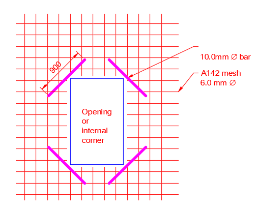
Good photos onoff! For all. Screeds and concrete shrinks. It cost pennies to do but where you have an internal corner just drop in diagonal bar, even if it is a poured self levelling screed or a screed with fibres. Even with fibres (plastic firbre ones definitley, steel fibres a bit less) you can still get crack development.. and this can cause you to worry that you have stretched your UF heating pipes.
-
Yes it is. There is a lot of real practical info on BH. If your just researching then the best thing to do to help yourself, save money and make in informed decision for your site is to learn as much about the ground as you can in laymans terms. Try if you can to read a little about clay soils, gravels, rock and how ground water behaves. Next have a look at your site.. what is next door for example? Could your neighbours do something at a later date that may say raise or lower the water table? Your neighbours could also include the council / water board assets for example; roads, parks, sewers and so on. Although hard to start you'll soon get a feel for the terminology of geotechnics and start to enjoy the fact that you are getting a handle on what can be a big cost risk. At first all you are trying to do is to learn enough so that you can ask the designers good questions. One of course is.. why are you doing it this way.. I'm paying you (designer) so can you explain why this is the best way to meet my requirements.. maybe you are just interested in the front end cost with say a 10 year guarentee or maybe you want more long term security / guard against water ingress say 20 -30 years down the line. If say you are near the top of a hill on free draining gravel ground (see saveasteading on gravel soils called Esker) then the ground water is highly unlikely to develop any significant hydrostatic pressure.. here you are really talking low risk damp proofing. At the other extreme.. jump now to say London and London clay which is pretty waterproof.. they use some of these type of clays to make dams out of. Here you could have other houses and say pavements close to your basement. Although the natural water table may be low you can experience times where water gets trapped against the basement walls. Significant water pressure can build up enough to damage your water proofing system. Sounds scary but once you have read a bit and learnt how soils behave you'll start to get a feel for your site and confident to ask the right questions. Select the right water proof barriers and water proofing system. This will be easier as you have an overview of what you need for your job. Lastly on a self build you are going to have to deal with the "builders". If you put this early work in then you'll get off on the right foot with the ground workers.. they will recognise that you "know a bit" and will be less likely to try and pull the wool over your eyes. They will then warn the brickie.. "Client knows a bit so don't muck about".. all the way up the chain!
-
If you have any DPM left pop another bit over the insulation as it can provide a slip membrane for the screed to shrink, helps reduce the risk of getting cracks in the middle for example. Maybe you are going / have done this anyway.
-
Hope this helps. Say you have some concrete pads to support columns. When the pads are cast they may vary in level, say + / 15mm. Often columns need to carry two basic forces, axial load and shear load. Sometimes they need to transmit a bending force to the concrete pad. There are three common ways to connect the column base plate to the pad. 1/ Cast in holding down bolts in cones. Usually waxed paper or polystrene. The cones are narrow at the bottom an wide at the top and this lets you wobble the bolts a bit to get them through the holes in the base plate. 2/ Cast in bolts with no cones.. need to be very accurate when doing this so avoid if you can. 3/ Place the column, drill out the concrete and use resin to fix the bolts. Works well with lowish forces. To get the column base plates level you often aim to set the top of the pad 20 -25mm below the intended level of the bottom of the base plate. The steel erector then uses shims under the centre of the base plate to get that plate level in the centre, then adjusts the bolts to pull the column plumb. It rocks about on the shim in the middle. Sometimes they use steel wedges round the edge of the plate to get it level and the column plumb. Now the grout. If you have cones then if they are not fully filled then the column can move sideways.. as the bolts still wobble about in the cone holes..not good! You can't get the cones filled using ordinary mortar as it does not flow enough to get under the plate and down the cone holes, and you can't compact the mortar in the cone holes. We know ordinary mortar etc shrinks when it cures.. and when it does so the nuts on the holding down bolts can come slack say after a month. The specialist grouts you buy are what we call compensated grouts. The grout contains an additive that expands as the grout cures and this is balanced against the shrinkage of the cement component. Hence the terms you see such as "non shrink grout. The grout sets up pretty quick. Once you get most of the steel up nip back and just give the nuts a check to see they are still tight. To keep life simple and for the cost I would just buy a bag of say the Sika 111 or a similar one part grout. all you need to do is add water as per the instructions and mix. If you start using a separate additive you'll only use a little and have to get the mix spot on. Make life easy and use the thinking time on the other exciting parts of your project.
-
Hello Grey Sage. You'll get plenty good info here to enable you to take a view on what is best for you. To get the best out of Build Hub can I suggest as a starting point you provide a bit of info on what you know about the existing construction. For example. The floors .. suspended or solid, wall type / cavities, roof construction, windows and existing levels of insulation. Also if you can give an indication of the floor area of the house and ceiling heights and number of storeys.
-
temporary habitation certificate and stairs
Gus Potter replied to Scoobyrex's topic in Building Regulations
Yes don't use MDF, use say 18mm OSB or an 18mm ply board as you can easily point to the load bearing capacity. This avoids the keen BC asking questions say about B&Q MDF, what happens if it gets wet? When you design a stair the handrail has to be able to carry a certain horizontal load and so do the spindles or in you case the ply say. No need to paint, if ply then when you are finished cut it up and make some nice shelves in the attic / garage with it.