


Gus Potter
-
Posts
2339 -
Joined
-
Last visited
-
Days Won
29
Everything posted by Gus Potter
-
It's gutting at times when you do a good job, no thanks, such is life.
-
How do you get into service that? We see it as now but once all the roof insulation goes in what then?
-
Open Faced Cladding - Batten SPEC?
Gus Potter replied to Duncan62's topic in General Construction Issues
Ah.. I appreciate your dilemma, this stuff is not common bedtime reading! To help best, can you post a drawing of the wall construction details, with notes. Don't give us a "half drawing" I'm not interested in drawing your teeth or being a detective, give us it worts and all. I assume your cladding is vertical? If not it's a different animal, but still can be designed. There is actually a huge amount to consider here, but fundamentally, once you understand how each element of the cladding build up works and interacts it's remarkably simple and you'll end up thinking.. that is so easy! if it's well explained to you.. which some of us will endeavour to do for you. If you post a DETAILED drawing of the whole wall make up then myself and others will be able to explain what is relevant to you, how it works (have a quick check you are not doing something daft in terms of the whole wall) , the timber service classes you require, fixings, suggest best options, things to avoid, where you can maybe source what you need at sensible cost and arm you with the questions that you need to ask a supplier. -
Great point Nick. Often we get what we call "water hammer in pipes" this is where there may be a bit of air, or occasionally pipe lengths that deflect. It sets up an oscillation in the "instant" water pressure ( potentially can exceed normal working pressures by a long way) that can destroy sensitive modern systems. over stress pipe connections. I would for all it costs.
-
Ground bearing slab curing
Gus Potter replied to flanagaj's topic in General Self Build & DIY Discussion
Ok, my suggestion is that you don't rush this. It's a key step as if this does not turn out the way you hope you'll store up loads of problems that you'll have to deal with later. The great thing about BH is that what your are doing is quite common and folk will fesse up the mistakes they have made, so you don't repeat them. We just want to help you out! There are few if any on BH that will relish hearing that it has gone wrong for you when we could have helped. In that context. You say you have a ground bearing slab and that BC have signed off what you are going to lay your slab on. Thus it may be assumed that it is reasonably flat and level. But BC won't have checked this for you! In general terms level means that what you are laying on does not vary too much from one end of the building to the other. Flatness is roughly a measure of call it "undulation" between often 3.0m points. A slab can be level for corner extremities but go up and down like a roller coaster in between. I suspect you don't know what tolerances you should be working to. This is your SE's fault possibly, it may be buried somewhere in you specification? You say you have a 150mm thick slab. Roughly if what you are laying on is 15mm high in places then this can start to compromise the cover to the mesh. If the top side of your slab coincides with a high spot in the sub base it really eats into the performance of the slab as you are reducing what we call the effective structural depth. Ok your sub base is down now. We can have a look at how and where you finish the top of the slab. Now as you are doing this your self I can tell you that slabs often end up high. Contractors, in rush often leave slabs high also more often than not, bugger off and leave someone else to fix it. A over high slab impacts on everything that comes after. But lets turn back to structural strength first and a bit of rough techy stuff. You SE will have specified a basic structural strength of the concrete. If they are doing their job correctly they should specify a level tolerance both on what you are laying on and the top surface. I do this as a matter of course, it can go horribly wrong if you don't as you can end up with a slab that is only say 120mm thick in places.. and it's sods law that the thin bit will be under the point where there is a bit more load. Your basic might be something like a C28/35 concrete, there are lots of way we can specify concrete. It's then up to you / contractor to find a mix that can be work into place / p[properly compacted to meet the level tolerances and concrete strength. Basic concrete is made by mixing cement, concrete sand and water. When the water evaporates we have voids in the concrete, like the cell structure in wood. Thus we want to design a mix that is workable enough, but does not have too much water as this reduces the concrete strength. We call this the water / cement ratio. We measure how workable the concrete is by using often called the "slump" test. Google this and read around. It will help you lots! Now we can also add things to the concrete, other chemicals and powders which also can slow down how fast the concrete cures and remains workable. One easy way is to use what we call an air entraining agent, similar to Fairy liquid (never add Fairy liquid to any concrete of mortar mix, it's dangerous) , the bubbles of air make it more workable. Modern concrete mixes use other chemicals and agents that make the concrete more workable (basically lubricate the mix) but without reducing the matrix strength. You mention SCC (self compacting concrete) this is often also referred to as self levelling concrete. But the big problem with SCC or other self levelling mixes is that they need to be handled by experts that do it day in and day out. They can very quickly "turn on the novice" within a matter of minutes. If they turn on you then they are totally unforgiving! My advice is to look at a basic concrete mix with a bit more water, what we call a higher slump. Phone up a few suppliers, tell them what you are trying to do, your labour limitations, the weather you expect and the size and type of slab you are laying. If you make the right approach nine times out of ten you'll find folk itching to help you out! In my day job as an SE I often design quite "whacky stuff" I have a good basic knowledge but often find myself phoning the experts on a particular product to see where and when we can safely explore boundaries of design. I do check what they tell me, but I'm long past the point where I feel embarrassed to ask for expert advice, or just ask a daft question. If it's ok for me to do it then it's ok for you to call up a few concrete suppliers and ask for help? You have nothing to lose but a bit of time. You need to reflect on what you are doing. It's ok to take one step back to make two forward later. -
How to unlock unlimited geothermal energy, anywhere we want
Gus Potter replied to SteamyTea's topic in Boffin's Corner
Interesting stuff, early technology, not to be ruled out. As an SE I've always been interested in rock mechanics. It's a fascinating subject, not bedtime reading for all mind. -
I agree. I've had a bit of a closer look. SE wise there is a sideways stability issue that may be questioned. This may be ok if the roof diaphragm is well braced and connected to the the main house wall. We can't yet see how you get into the extension from the house? Again this has SE implications. The drainage looks like it needs clarification and so on. Anyway, one should always not judge a job half done, thus I'm reticent to be too critical at this stage.
-
While getting rid of thermal bridges is admirable you need to remember that you SE needs to connect the structure together to stop it falling down, or deflecting, shrinking so much that you don't end up with a duff house. Now if you go over the score with your mitigation of thermal bridges, this can make the detailing so complex it becomes unbuildable, I'll have to introduce work SE arounds for example, the build cost and detailing time starts to rocket exponentially. Your builder will charge you for what's on the drawings.. and if it looks hard, add a premium, but often never actually deliver what you are paying for. Keep the design simple. To do this you have to embrace holistic design, from the foundations / ground investigation up. This makes it hard for self builders who want to split the design into different stages which is common on Build Hub. The trick many miss is not to get an experience designer on board early, even if just to keep a watching brief on what you're up to pretty much from day one. I do this from time to time even though my real work may only start later in the project. it also gives you time to find out if you like me, and I you! it often gives us an easy exit route if we don't gel, little money / programme time, if any, is lost. It make a lot of sense at my designer end as if I've kept any eye on the earlier process I can often avoid having to sort out a mess before I start on my own part of the design.
-
Try and post your drawings, you'll get loads of targeted advice if you do. How refreshing to hear, well done!
-
Previously unknown basement rears it's ugly head
Gus Potter replied to kandgmitchell's topic in Basements
For me this is a interesting challenge to design a solution. I appreciate that you find it far from interesting and it's a worry. Stage 1: One option I would be inclined to look at first is to install another beam or beams below the ones you have if it turns out they are so heavily corroded they are well below capacity. Remember we would look initially to design these for the latest loadings prescribed in the design codes. The following is based on using a trick we deploy when we are needing to support say a large opening in a historic building or repair steels, more applicable to you. The existing beams have a point of support on say the main walls. Thus in the round we know these are the strong and proven points. It's a reasonable starting assumption the walls locally will have pretty much finished settling in and around the existing supports, thus we want to put our new point loads at these positions. Let's say, as we don't have much information that the beams are supporting the ground floor flat but also an internal spine wall that runs up the building and it turns out there is a fair bit of load. It make the challenge more interesting. This is in a bit of reverse order. How do we calculate the loads and do some other thinking. Well the loads are easily calculated once we know the building layout, floor and roof span directions. From that we can calculate the forces on the existing beam/s. We would want to split these between permanent loads ( dead loads from the materials) and imposed ( live loads) from people, furniture, snow roof load etc. Next we would want to have a look at the existing corroded beams, try and identify their section properties when new and as they are now, corroded. We can then make a reasoned guess as to what their original design strength was and what it is now. The extra thinking comes for example as one obvious question is why has it not fallen down to date? Have the beams deflected a bit too much and shed load elsewhere. Remember a building does not often fall down until it has exhausted every alternative load path. This is what SE's often call redundancy, which helps stop what we also cause disproportionate collapse, like the domino effect. We would want to get a handle on this before we access any confined space. Any Engineer is going to want to do a pretty comprehensive dilapidations survey. This heads off any "adventure’s seeking to take advantage, but it also protects the honest residents if some further cracking occurs during the works. In summary stage one is doing some fag packet calculations, a survey and from that we can get a feel for how the building is "working". Stage 2: Again not quite in the right order but it easier to hold the narrative. Lets say we can install beams under the existing, then do some bolting etc to support the loads, maybe by stiffening the webs of the existing beams or by using other simple plates / angle sections. This means the new beam/s load the supporting walls in the same place, proven to have worked so far. The big thing is that there is a good chance you won't be able to get the new beans into the basement in one complete length. Thus splices will be required, which tend to flex a bit. Also critically the new beams won't take up the load unless we pre deflect them. For them to carry load the building would need to settle onto them.. high probability of cracking as we move up the building. There is a technique we use on historic buildings where we get the new beams in with a bit of clearance and then jack between the old beams and say the top of a new beam to pre bend the new beam so it takes up the load. We have calculated the loads so have a bench mark as to how much we need to jack / pre bend. We are only talking mm here so we would use say dial gauges. In practice what we do is jack it a bit then run up stairs and see if cracking is starting or if existing cracks are opening up, doors starting to jamb an so on. This takes time, it's not a one day job! Stage 3: As above and in reverse order. The new beams often need to rest on a new padstone below the existing one spreading the load from the existing corroded beams or we need a spreading arrangement. This is partly a detailing and practical thing. But once access is gained with a fair wind usually there is a way of applying the load to the supporting walls in the same place as the existing beams are. Again simplistically we just trick the building, it's sub structure into "thinking" nothing has changed above. But this is not an exact science and 99% of the time some minor movement will occur and that has to be communicated to all parties. Comment: Infilling the basement or sifting the loads to a different place invites lots of potential settlement problems and so on. You would need to investigate the basement floor and the soil under which is going to be less consolidated than the soil under the main load bearing wall for example. Construction safety is going to be the driver here in terms of a structural solution. I would look to have at least head height clearance for folk to work. Two means of escape from the basement. Make sure we have a good ventilation strategy during and after the works, avoid any welding, use of volatile paints etc and make sure there is compliance with all the regs relating to working in confined spaces. In summary it may turn out that the SE solution is not complex, it will likely need a diligent / experienced and well supervised Contractor. The hard part is herding the rest of the cats, project administration and agreement of where the liability lies etc. This goes along way towards explaining why many designers don't want the hassle of a project like this, the design fee has to be attractive not least. -
Ground bearing slab curing
Gus Potter replied to flanagaj's topic in General Self Build & DIY Discussion
You have my phone number.. you know the rules, text me first as I'm a bit deaf and I'll help you out for free for half an hour. You just keep digging yourself a hole you fanny! We have I believe talked already engaged by email? I'll give up a bit of my time for free 30 minutes and that's it. This is my last and final offer. You are so out of your depth it’s bonkers.. but I think you are just stubborn and that is is you downfall. You are not even out the ground yet! On balance of probability you are going to regret this. You seem to be falling for, say the casual internity trades folk. You are off your head! It's time son to get your big boys hat on and wake up and smell, the coffee. This is tough love but I recommend that you also call/ pm @Nickfromwales for a very quick chat. His time is not free ( I think you get 15 -30 min pro bono) but it could be the best call you ever make! You have not even got out the ground yet! -
Economic design of the drainage field after a digester tank
Gus Potter replied to saveasteading's topic in Barn Conversions
The regulations can be wrong conservatively.. leads to over design and you lose a bit of money, but they can also be horribly wrong! to the extent that it makes a building plot worthless. @saveasteading has the advantage of a large plot.. you can often get something to work here with a bit of imagination. -
Raising build height and planning permission
Gus Potter replied to PSC88's topic in Planning Permission
Ok good points. But as a designer.. if you came back to me and asked.. is it ok Gus to bump up the ridge height? Given that it is not going to say cause an over shadowing problem, it is well away from other development as above and so on. I would say to you, ok fair point but this is not the end of the consideration. Raising the ridge can introduce a what we call "massing" in Architectural terms. The wall / roof relationship changes for example, the mass (size) of the individual elements (be that render cf the roof tiles for example) can suddenly become unacceptable as their proportion relative to each other changes. Then if we make the ridge higher we can invite what we call a "scale" problem. The house is just bigger in elevation for example. This could be relative to the skyline or the ground levels. If you want to ignore this then you are taking a risk.. Sometimes the risk is low, but the consequences can be catastrophic.. but the Daily Mail may pay you for your story! If any Client asks me if it's ok to just pop the ridge up a bit.. I would try my best to discuss with them the risk they are taking, make contact with the planners for clarification. If it's obvious to me that it's daft and the Client persists, I'll probably withdraw from the project as I don't want my name in the Daily Mail either. @ETC may be able to add detail to this or be better able to comment? -
Sticking Aerogel to steel
Gus Potter replied to Great_scot_selfbuild's topic in General Construction Issues
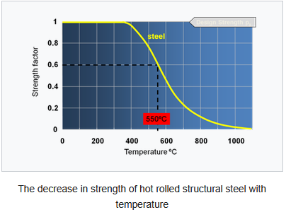
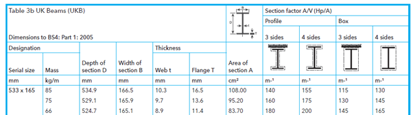
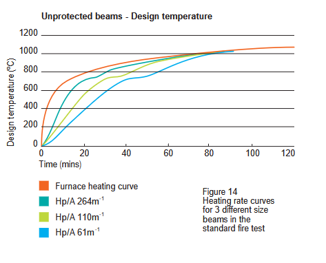
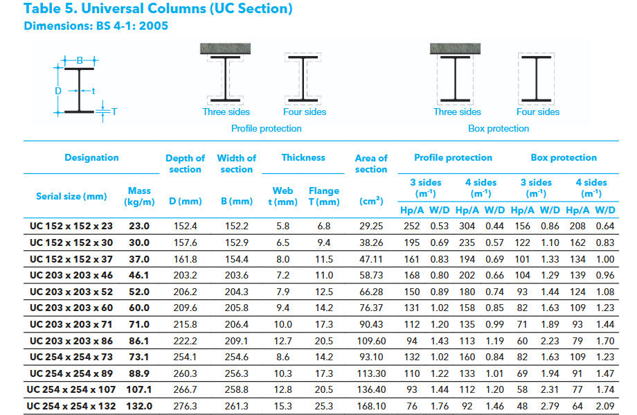
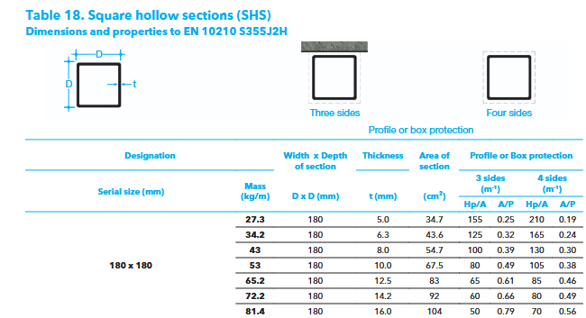
It depends! But here is a rough outline of how we go about designing steel fire protection. The following is in the context of the self builder, not multi storey, multiple occupancy structures. Ok, the process / theory is.. roughly this. The starting point is to understand how steel behaves when it gets hot. Someone ask me / others a while back.. why does my oven not start to melt / distort when I cook a pizza hot? The above is what we call a fire curve (SCI, Steel Construction Institute data ). There are different fire curves. They vary depending on fire loading (how much and what types of stuff can contribute to a fire, how "intense and rapid" the heat delivery) but the above is one we would refer to in a typical domestic self build. You can see that up to about 350 Celsius the steel maintains much of its strength, which is why your oven does not "melt" and fall to bits. After that the steel strength starts to plummet. When we fire protect steels as @saveasteading says This is correct. All we are doing it to stop the steel from getting hot enough, then soften too much, and thus not carry the loads on it for the time required by the building regulations for example. Now we can either select a geometry of steel member and make it very heavy such that there is so much mass of steel that it does not get heated quickly enough to soften to the point of failure. In lay terms. If we had a solid round bar of steel say 150mm in diameter it has a large cross section area compared with the exposed surface. This is what we call the heated perimeter / cross section area ratio (Hp/A), the Euro codes have slightly different way of presenting but they mean the same. They are presented using the ratio Area / Volume, A/V. But if we have the same cross section area of steel and weight in an I shape (a universal beam) it has a much larger surface area and thus will heat up much more quickly and thus lose strength more quickly. Now we ain't going to be using solid 150mm diameter steels. What we could look to do is is insulate the steel. This could be by way of fire proof plasterboard or intumescent paint. But also we could build the steel into a masonry wall and maybe have only one side exposed to the fire on the inside of say a garage. Or we could have the steel built into a floor that in itself insulates some of the exposed faces of the steel. Below is a screen shot of a table that shows how we need to consider the exposed sides. They key here is that the lower the section factor the slower the steel will heat up. The section factor changes depending on how many sides of the steel are exposed. But to go back to what @Great_scot_selfbuild asked., which was how heavy does a steel need to be so it does not need fire protection? The info below is taken from Corus literature 2003 as an easy generic example. The bottom line (Hp 61m^-1) is of interest to us here in a domestic self build. Using a design temperature of 550 deg you can see that the bottom blue line hangs in there, all other things being equal for 30 min. So let go back now and find a steel section with a section factor of lower than 61 m^-1 to try and get a handle on how big a column needs to be for example. A 203 x 203 x 86kg/m is a candidate if it has three sides protection (section factor 60), but that is a heavy steel. You also need to handle this safely on site. Ok let's see how a box section compares. Ok we can get down to 60 for three sides exposed protection.. not much difference. But if we reduce the sides exposed the numbers get a lot better. I've not shown them here. That main remaining key bit is what we call the load ratio mentioned above as 0.6 ratio. When we design a beam / columns or pretty much any structural member in your house we design for the normal expected loads. The self weight, permanent loads and the imposed ( live loads, people, book shelves etc) but in a fire we recognise that the floors, roof etc are probably not going to be fully loaded with people for example during a fire, the permanent / self weight load is still there. So we can make a reduction in the load if a fire occurs. Its based on probability and the loads that could be reasonably expected in the case of a fire. We call this an accidental load case and the safety factors get reduced for example. If we designed everything for the worst case buildings would be too expensive to build! The load ratio is the load (stress generated) during a fire compared with the ultimate capacity of the member. Often we design beams to be restrained by say a timber floor.. but if this has burnt away we can't count that. To conclude: The above I hope, gives you all a bit of insight into what we need to do / think about to design steels for fire. The take away is that sometimes it works using a heavy steel to avoid the expense of fire protection. The design can become much more complex if bolted / welded connections need to be taken into account. This kind of design consideration is a bit complex if you've not done it before, it's not common bedtime reading! It can be a tricky subject once you get into detail, something that many Architect's, BC officers are also not too familiar with. But it's a fundamental part of producing a safe design. My objective in writing is to try and help BH folk gain a bit more knowledge so you can ask and phrase any questions you have to your designers from a lay person perspective. You make a good point. Yes steels expand in a fire and will change shape and distort the surrounding structure, to the point it often has to be later demolished. The objective is that the building hangs in there so it does not fall on the fire brigade, set light or fall onto a neighbouring building not least.


-
This puts any of our challenges into perspective
Gus Potter replied to saveasteading's topic in Boffin's Corner
Unlikely there are any record drawings, photos, back then photos were expensive to take, gut feeling is that there will be no meaningful records. From time to time I work on old buildings, we add load, change the load pattern (the floors get loaded in a different way as the use changes). For me it is one of the most rewarding types of design to undertake. It starts with researching the history of the construction and what the site was used for before construction, anecdotal information, ground conditions and so on. It is hugely interesting.. the history, folk think SE's (the failure we see of the column) just do sums but we don't, there is much more to the job. Frankly the maths are massively boring once you have done it a hundred times or more. What I find exciting and rewarding is the "detective work", the history, working out what has caused the failure I see. Then you need to convert that into say a report that a layperson can understand. The fun part of being an SE is the art and craft of design and detective work , but knowing you can "prove what you are saying". Now in all that,we at times need to exercise Engineering judgement, some of the maths are based on probability, some empirically based, but again these maths need to be presented often in a way that a layperson ( a lay person also includes most BC officers) can also understand. Yes there is. We can often identify historic steel sections. I have documents in my library that helps me do this. Once we have dated and potentially sized a section we need to look at the strength. As we go back in time the manufacturing process was less controlled and a bit dodgy cf modern terms. Thus we need to use a different set of safety factors for example. So yes Alan we can do it more often than not. I've attached a historic copy of the Dorman Long Handbook from 1906 to let all see the kind of things I look at. This is just one of the fun parts of my job, you can do the maths, takes time and study to learn this.. but then you get to be a historian.. a detective, when something goes wrong the person that can actually design a solution and keep folk safe. If any of you have kids, being an SE is not the worst job in the world! If your kids are ok at maths then they stand in good stead. For me the being an SE is about the art and craft of design. The best SE's are actually really creative folk, you need some thinking logic, the maths almost comes secondary. Dorman Long 1906 handbook.pdf -
Raising build height and planning permission
Gus Potter replied to PSC88's topic in Planning Permission
Just ask the planner, drop them an email and get it in writing. Disagree as we have no other information. -
I think you're right. Had got myself over excited with the SE stuff! Hope all is well at your end.
-
This puts any of our challenges into perspective
Gus Potter replied to saveasteading's topic in Boffin's Corner
What a belter of a photo! Now funnily this serves as a good example, all be it on a smaller scaler, as what not to do if self building or extending your house. I make some points. It's debatable. Technically to me it looks like a Universal beam, if you look at the flange width cf the web depth.. it look looks a beam, a column is more squat in profile. I can see from the photo the beam has buckled perpendicular to what seems to be a heavily loaded transfer beam at ceiling level. My gut feeling is that either the designer has made a massive cock up in calculating the loads on the, now call it a column. More likely is that they have not understood the top and bottom connections. They may have designed them as pinned, but then inadvertently introduced a stiff connection or some off centre loading ( called an eccentricity) that introduces a bending force in the column and not spotted it. This extra bending force reduces the capacity of the column to carry load. But on the other hand the Contractor may have thought they know better and just gone off and done their own thing. My experience of Contractors / project manager is mixed, I used to be a Contractor myself. Some think they know it all, some are arrogant in the extreme (pride comes before the fall) some are sensible enough to just make a call to the SE, which I now am. Now the photo is of a big building, heavily loaded. But when I design houses, wall slappings for extension etc the loads are much less, but I design with much smaller steels, thus pro rata they are doing just as much work. The design is lean. But if you listen to your builder without checking you are taking a big risk, don't be swayed by bravado, a builder telling you they know better. At the end of the day if the builder changes the design in any way and something goes wrong their insurance won't cover it, and possibly your home insurance won't either. It also critically unsafe. My advice is, if you want to deviate from your design drawings then call the designer, just lift the phone! IT'S THAT SIMPLE -
Sticking Aerogel to steel
Gus Potter replied to Great_scot_selfbuild's topic in General Construction Issues
Ok a bit of food for thought. You have a steel column, likely supporting a structural load. Let's say as a minimum you need some fire protection? Say 30 minutes. Now you can achieve that in two common ways. 1/ Box it in with say Gyproc Fireline board. Which probably gives you a detailing problem, which is why you are probably wanting to use Aerogel as it saves space. 2/ Paint the steel with intumescent paint. But for intumescent paint to work it needs to have space to expand into... you see the dilemma? As a rough rule of thumb the intumescent paint thickness needs to expand some 50 times to work properly. It needs space to do this. So you can't stick Areogell to the steel per say and you need manufacturer approval to stick it to intumescent paint. Now often BC etc don't pick up on this. But if something goes wrong, there is a fire, the steel fails and the building falls on say the Fire Brigade.. then the buck has to stop somewhere.. as an SE I'll be on the radar, Architect's also, and you if you have taken it upon yourself to become a designer then you are facing a huge liability. Now the above is a worst case.. but if you get a smart BC officer that knows about this stuff then they might be minded to fail your design unless you can prove otherwise. There are cases where the steel is well protected by masonry and very heavy and thick and thus possibly as at Paulie I think in Paulie's case the steels are so heavy they don't need fire protection. The load we use when designing steels for fire protection get reduced as they are called an accidental case. In lay terms we don't design most steels for the building being fully loaded up and a fire starting at the same time. I would go back and look at what your steels are doing, the loads and so on. Also have a chat with your SE to check if what you are proposing might invalidate their design for example. I appreciate you may not like this news.. but it's up to you and your risk. -
Good questions. A soak away draining too quickly can be more easily mitigated than one that drains too slow, the too slow causes problems. Often you just need to understand the ground composition, then adapt the design a bit.
-
Interesting question. The one metre depth may actually be to do with health and safety in terms of accessing an excavation without support. If your house is on a slope, on a hillock then we don't want the water just running out further down, especially if it is from a septic tank for example. Sometimes it works to sit a soakaway deeper, for example there is a gravel layer a bit deeper down that can accept a bit of extra water. There is a trade off in that the excavation is deeper thus more cost.. but in a good gravel layer the soak away can be less extensive. What you mention 1.8m depth seems more like an "Engineered" solution which can be elegant and offer best value for money while still performing.
-
Yes agree. Moving the drain outwith the building foot print is the safest option and would probably simplify the foundation design and thus possibly reduce cost.
-
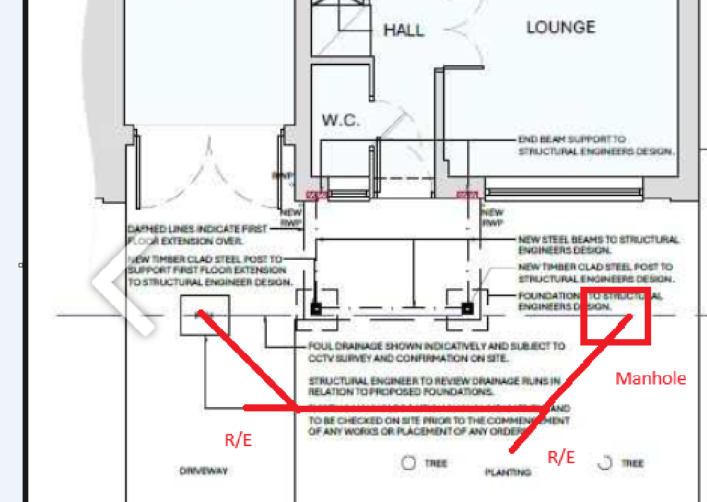
Would this help? It looks like you might have space to move the public sewer outwith the zone of influence of the new foundation? I'm assuming the direction of flow runs left to right on the drawing. If not then just reverse the diagram. For reference a private drain is a drain that serves only one house, a public sewer serves more than one house and often this asset belongs to the water board. As others have said you should determine,if you need build over permission for this, you will need permission to move the sewer, build over or near to it. The notation R/E indicates a rodding point. Best to do it right to avoid later potentially horrendous complications.
-
Can you post a drawing of what you are going to build. The figures you present seem high at first glance. But I often do these types of design, they can be very time consuming, although small, and thus the fee cost is higher in proportion to the floor area. To put this into context. I have a potential Client that needs a modest new build and the design fees are similar to your over all fee. An interesting number is £120/hr for site visits. Now the 120 rate is fine if for time spent on site as there is travelling and then inevitably writing emails etc when back in the office. But if it is also booked at £ 120/ hr for travelling and then writing emails when you get back to the office then that is different. Do that and don't be afraid to ask questions.
-
Agree, you might open a can of worms.


