


Gus Potter
-
Posts
2384 -
Joined
-
Last visited
-
Days Won
34
Everything posted by Gus Potter
-
Replacing(and lowering) existing timber floor with concrete floor
Gus Potter replied to DeanAlan's topic in Concrete
Tony.. Was just giving you a gentle ribbing, but thanks. The first part of the doc is good reading but the latter may be a bit out of date. Yes the operatives are not wearing flared trousers but the physical properties of materials have not changed since 2007 (in so far as I'm aware) .. put that caveat in as I think this may appeal. -
Replacing(and lowering) existing timber floor with concrete floor
Gus Potter replied to DeanAlan's topic in Concrete
Not aiming to miss here TonyT! Anyway, in the spirit of BH a bit of banter does no harm and is fun. One good reference document I use is "Rising damp in walls - diagnosis and treatment" published by the BRE. I have a copy but can't post due to copy write etc. Current price seems like £15 quid. It's worth the money compared with a say "Domino's pizza".. of course if you are hungry then a Dominos wins. The guidance it pretty user friendly so you don't need to be an SE to understand it. Here is the link: https://www.brebookshop.com/details.jsp?id=287528 @Adsibob don't panic if your founds are sitting in water, it's quite common. @DeanAlan I think this £15 may help give you some confidence how to progress, marry that up with the comments on BH and the cost effective / practical solution may be there for you. If you think about it you will pay a Surveyor a good few quid, inform yourself and talk to them. They will then know that you know a little about it and will often put more effort into the report as they may well be more invested in your job, over and above what they normally do. It's a people thing.. funnily, folk like passing on knowledge as you often see on BH. -
Hello @Visioner101 and any parents out there with kids applying for jobs? Interesting post, enjoyed looking at the photos. Here are a few of my own thoughts for anyone that is at uni and has the self build dream. We know that often the first step is to get a job after you leave uni.. most folk need to borrow money.. no job..often no lending unless it's Mum and Dad...? Visioner.. if you want to go into fund management say then you'll stand a better chance of getting the job you want if you can get a good handle on the mechanics of cost vs return - call that profit and loss. For all. If you are willing to spend a bit of time you could build quite a nice supporting document to support a cv that demonstrates that you have an understanding of the actual mechanics of property development / house self building financing on a small scale, small contracts, the pitfalls and so on. All though this may sound miles off track from high finance it can demonstrate to a prospective employer that this individual has potential as they are able to analyse a particular market, understand it and make rational decisions / recommendations. For all (parents) and including Visioner. BH is a fantastic resource and really, all the answers / info are here that could make a job application stand out, you just need to spend some time reading and learning. I make a living in the construction industry and would always welcome a cv supported by a document that demonstrates that a young candidate has gone the extra mile and is seriously interested in their chosen path. For any parent reading this, it does not have to be technically correct. What is does require is to demonstrate that some effort has been put into the document and to a small extent some logic and critical thinking has been applied. An employer that disregards such a supporting document is probably not worth working for anyway. All the best to Visioner and first time builders.
-
posi joist design problems - intersection with lintels...
Gus Potter replied to sean1933's topic in General Structural Issues
Hi Sean. @sean1933 "The frustration I have is that where the joists are built in they obviously go from bearing on a block, to bearing on the lintel (which is some 5mm thick + mortar bed = 10+mm)... thus meaning they are some 10mm out of level the joists next to them. Solutions I have considered: .." It's wise to look carefully (as you are doing) at the implications of making what appear to be small design changes. @mvincentd " No mention/discussion of 'load ratio' and no references to it in Catnic product details/specs, so I wonder if contractors ever give it consideration..." Yes some contractors do. This info can be a little harder to find as sometimes it is not presented in the load tables. However, in the Catnic brochure this info is presented at the end, under the heading "Technical Information" Here is a link to the Catnic downloads https://catnic.com/downloads Follow the lintel products selector for the pdf brochure and the load ratio info is round about page 64. @Gus Potter or "take advice from the brickie". Apologies as this is a bit of a sweeping statement, should have qualified it a bit at the time of writing. Yes it can be helpful to take on board advice from experienced brickies etc. But always check with the designer as they are best placed to assess the structural implications of any design changes in terms of say global building stability. If you are proposing to alter the support conditions of say floor joists always check as the floors are often used to provide lateral stability to the walls. Also, look carefully if you are using hangers / brackets /resin fixings as some are able to carry different amounts of axial load (tension / compression) in the joist as well the vertical loads. The tension / axial load arises when say for example the wind is sucking the walls out and you are relying on the hanger (other type of connection) to tie the wall back into the floor. -
posi joist design problems - intersection with lintels...
Gus Potter replied to sean1933's topic in General Structural Issues
Hello all. A few thoughts. Before you start changing levels, methods of hanging joists, packing things etc it is really important to get a handle on the basics. Take a simple beam subject to vertical load. Often to perform it has to be kept vertical, not twist, or move sideways. We call this lateral and torsional restraint. Quite easily, if you muck up the restraints you can reduce the capacity of a beam / wall so much so that it will fail, sometimes even before the building is erected. I have seen this happen. Often a beam is designed where say floor joists are framing in above and provide this "lateral restraint". There are general rules that say for example that a mid floor joist can provide lateral restraint to a lintel or beam. But if you start to introduce packers and so on it raises some questions as you can introduce an extra slip plane, the assumed friction can be lost, thus the effective restraint is lost and this is not safe. I have quoted mvincentd.. it's a good photo. mv.. mentions a green roof.. which is heavy, hence probably the heavy twin engineered joists. Here you can see double joists framing in on the inner leaf of the lintel. The lintel is a cold formed steel lintel, say by "Catnic" or "Key Stone". For all. Please bear in mind the following: Catnic for example quote the capacity of their lintels base on a uniformly distributed load. That means that roughly the load is applied fairly evenly along the length of the lintel. Just as importantly they also specify what is called a load ratio. To allow the lintel to meet the stated capacity both the inner and outer flange loads have to fall within certain limits. In other words you can't put all the load on the inner flange and expect to get away with it as the lintel starts to twist too much. Having a cursory glance at the photo it seems that we have two double joists on the inner flange and very little load on the outer flange. All is not lost however if you want to go off piste and the load ratio is exceeded. You can contact the manufacture and ask them to check that what you propose is ok. The overall load may be less, while the load ratio may exceed the brochure limits they can check it will still be adequate. Please be aware of the consequences when changing the support details. Remember that the engineered joist manufacturer will often take no responsibility for anything other than their product.. be careful what you do. It's also worth thinking about how the lintel is supported at the ends. You can see from the photo that the double joists are more towards one side, thus the load at the right hand support will be more than the left. A consequence of this is that the lintel is subject to more of a shearing force at one end than the other. So again, it's worth checking this with the manufacturer. If you have an uneven load on the supports which the photo shows this is a flag for any checker. It's an aside, but you can see the wavy scratch marks on the block. Often folk think this is to provide a key for the plaster, but it also identifies the manufacturer of the block and the block strength. mv's photo is great. You can see the clear wavy marks, looks like there are four per block and the wave has a "defined shape". Thermalite/ Hanson have same photo and this looks like their High strength 7 block. So if you are doing a refurb garage conversion this info can be really helpfull when you maybe want to rest a beam / padstone on this kind of wall but don't know what strength it is. in summary please think carefully before you make what appear to be innocuous changes, or "take advice from the brickie". It only takes a few minutes to phone the Architect, SE or if you can't get hold of any of the former post here to get some possible pointers. Rest assured from their (SE etc) point of view having the Client calling them with the odd query is no problem as can often head off serious time consuming / problematic issues later. -
Hello patp. It may be worth while doing a bit of research to try and understand what the causes are for the flow rate. This may help you get a handle on the possible capping costs. Once you have a bit more information then it may be that you are in a better position to persuade. In some ways your neighbour may reassured and engage. They are maybe just wary / defensive at the possible cost implication, hence the response you are getting. It may be that they are able to recoupe any cost from their insurer. While it may seem a bit late in the day you may be able to resolve this. If you are willing to spend a bit of time (it can also be fun), then you may reap some reward, if not then all you may lose is some time. For all. Very simplistically an artesian effect can occur when you are near say near the bottom of a hill. The rain falls on the hill, soaks into the ground and makes it's way down to the bottom where it often goes into a river / stream (burn). If the soil is pretty much all the same at some locations the water that has soaked in at the top will come to the surface lower down and can be seen as small springs during heavy rain. You often see this when you are out for a walk after heavy rain. However, what can happen is that say halfway down the hill there is maybe some glacial material (call it clay) which forms a waterproof layer over the underlying soil. Here the water that has fallen on the top of the hill gets trapped under this "clay layer" and as you go down the hill the pressure builds up as the water can't easily get to the surface. If you drill a hole in the ground as maybe in Patp's case being at the bottom of a slope and puncture the "waterproof" layer, then you can get this artesian effect. There are other ways this can happen where you have say rock. Generally " solid" rock (granite say) does not transmit water but the rock has fractures in it and it is the frequency and size of these fractures that can convey different amounts of water. This can also, but less common, can manifest as an artesian effect. Mostly it crops up when tunneling, and basements! Bearing the above principles in mind you could again separate this into two (I'll leave out rock strata - Chalk, limestones etc and concentrate on clay type soils) . Patp, Is it a case where you have a thin layer of clay and not much of a slope.. this would suggest lots of low pressure water but plenty flow or a thick layer of clay, more elevation, small puncture hole and lots of pressure? Much will also depend on the type of clay and you can find info on this too. If you have a fine clay then this can wash out more quickly and so on..don't despair just follow the logic. One way patp can get a handle on this is to draw in section the landscape (refer to OS map say) , just roughly. Then have a look here ,see link, below for a learning resource. http://mapapps.bgs.ac.uk/geologyofbritain/home.html The above will give you a rough idea what the ground might be like and compare this with the OS map that shows the contours of the ground. Also, have a look on the council web site for info, COVID excepted your local BCO will be familiar with the ground, ask them. Have a look at the old historical maps that are available online. Even as a lay person you can build a picture of what may be likely going on under the ground. What you are doing is akin to a desktop study. Save all the info you gather as if you need to get an Enginneer in you may well find that you have done some of the leg work for them. It sounds like patp may have a situation where there is indeed some kind of clay, (really fractured, weathered, soft surface rock ?) acting as the sealing layer trapping the water. Over time the water flow will have eroded the "clay", the hole has got bigger as the soft fine material get progressively washed out, thus more water is coming out the ground as patp is observing. To cap this may well entail two different methods depending on what water pressure / flow rate you have, how much the original bore has open up by and so on. I'll stop here with the background info, but in summary with a bit of research on your own and while you may not be able to solve all of it you will much more informed when it comes to making the financial judgements and often, this will give you piece of mind that you are on the right track, maybe also save some money! Patp. This is a guess here but it looks more like a situation where the flow is increasing as you have some kind of soft material / lower water pressure (hydrostatic) that is being eroded rather than a high pressure with rock. If the former, it may be that you, as the other members have suggested may be able to just pump in some "bentonite" which is a kind of a heavy/ dense "sticky", "clay" type material to seal (gunge) it up.. Bentonite generally works as it is dense and does not go hard like concrete, which then shrinks. While you could try and pump in concrete all that may happen is that within a short time the water will find it's way round the concrete plug and you will be worse off as you have blocked up the hole with concrete and can't access the "leak" in the water proof layer" For all.. Just to finish. It may well be worth while this effort. You may be lucky and get your neighbour to engage and move on with no ill will. If not then you will have a much better grasp of the situation, be more familiar with the geotechnical terms and so on should you, after exhausting all other options, need to proceed down a more formal, route.
-
Replacing(and lowering) existing timber floor with concrete floor
Gus Potter replied to DeanAlan's topic in Concrete
Hello Dean. Welcome to BH, it's a great resource. "Q2: current DPC is a badly compromised slate DPC (was checked by a damp specialist and visual inspection tells you all you need to know) and 600mm or so above ground level. I will need to bring the new DPM from under the new concrete slab up the walls to lap into the wall above or below a new chemical DPC? When they say 'lap in' does that mean a shallow horizontal trench (10mm?) cut into the masonry (or mortar) " Generally slate DPC's last a very long time. Yes, they may get the odd crack in them as an old house moves about but the odd crack in it's self will transmit very little moisture by way of capillary action if it is small, if large then then even less so if not bridged. You'll also often find that the DPC is roughly level with the floor and any solum vents. If you wish post some photos you get additional feedback. One thing worth considering is that if you are breaking up the concrete floor you can recycle this if you keep the lumps under say 75mm and mix this up with the fines. You'll often find you can whack this in and get it quite "tight" then top it off with a little MOT type one if need be and your blinding. Saves on disposal costs. Have a look on the net at what is called 6F2 / 6F5 recycled aggregate and compare this with what you might end up when you break out the floor.. If you are breaking the floor up by hand as opposed to getting a mini digger in with a pecker (maybe not so good for the old house) then you'll be surprised at how much good material you can recover... and save on skips etc. -
Thanks Peter, learn something new every day. Here is a question. A while ago I was working with a traditional sparkie and he referred to this area (see below with the question mark) in an attic / loft truss as being the "campsile" not sure if I have the spelling right. I think this may be an expression local to Lanarkshire in Scotland. For example we call noggings " dwangs" in Scotland. What is it called in other parts of the UK?

-
Hello gc86. Sounds to me that you are taking a pragmatic approach, keeping the lines of communication clear, not falling out. Althought this may be the immediate concern don't forget to look after the kit on site. Make sure that all the panels are stacked and supported so they don't start to twist. Keep them off the ground with plenty ventilation underneath them. Double sheet the top on battens so the air can get all round the panels... over the top too. Get all nails, brackets hangers etc inside and keep them dry. Doing this may actually help the timber season more so you'll get less shrinkage later on.. every cloud has a silver lining.
-
Hello gc86. This can be frustrating to say the least. If you look at it from the Surveyors point of view. The kit is on site but who knows if it is the right size and so on. Believe it or not it happens! If you default on payment of your loan then the lender will try and recover and the surveyor is on the hook in terms of any extra value they attach to the unerected kit. During the recovery process (if default occurs) the kit could be exposed to the weather, the ancilliary parts.. brackets steel are easily thieved. That said, if you are say constructing a large industrial steel building a payment is often made when the steel frame is delivered to site or fabricated and in the fabricators yard. To enable this sometimes requires the SE or the person who has prepared the fabrication drawings to go to the yard and measure everything up to make sure that what has been fabricated matches the fabrication drawings... and that comes at a cost. On a small timber frame this is less practicable. If you can, the best way as you probably already know is to push on, get the kit up with a semi watertight membrane on the roof, board up the windows if need be. Now you are at the common milestone (valuation point) of wind and watertight.
-
Zinc angled standing seam.
Gus Potter replied to Makeitstop's topic in House Extensions & Conservatories
Cracking photo, looks great, Russdl. The zinc can make for some great clean lines. Just teasing, but are the wheelie bins always in line too? With some roofs, especially renovations with say an irregular smaller slate (eg Ballachulish) or maybe a pan tile roof you can often get away with a few lumps and bumps. I think the zinc is less forgiving..? but it can be worth the extra effort in the right circumstances. -
Zinc angled standing seam.
Gus Potter replied to Makeitstop's topic in House Extensions & Conservatories
A well done zinc roof can look fantastic. One of the keys to achieving this it to design and prepare the substrate properly. Make sure you detail for condensation too! For example, sometimes you may have a gutter detail at the bottom with a lap. Study the manufacturer's installation details really carefully as you may need to use a slightly thinner "sarking board" here so as to avoid a bump in the zinc. Also, make sure you isolate the zinc from dissimilar metals that can cause significant corrosion of the zinc and quickly spoil the roof. You'll find a lot of this info in the manufacturer's literature. Follow this and you will have a roof that lasts, often beyond expectation. -
Can I lean on the experiences you guys have learnt
Gus Potter replied to Sally's topic in Building Regulations
Hi Sally. As Jilly etc allude to it's well worth getting an SE in as early as you can. What you descibe is often called a corbelled brick foundation. You'll often find these. For example up in Glasgow area these can be found in houses / some farm buildings etc predating circa 1930's say. Although the founds may seem shallow (yes they are not deep enough to comply with the modern general guidance for frost cover) they may well be fine. There are a lot of different types of clay, some rock solid that can easily take a bit of extra load, some less so. Also with clays you can sometimes get a "crust". This is where the top layer is stiffer than the underlying clay. Sometimes on new build we can take advantage of this and sit the founds in the crust, the load spreads out as you go deeper thus when you get to say a softer layer of clay the stress on this softer deeper layer is reduced. What this means in practice is that sometimes you are best to leave the soil under the founds undisturbed.. no underpinning etc. As SE will look at the existing structure, see if it has moved about.. or not and may conclude that it is best "left alone". To avoid adding extra load to the outside existing walls you can sometimes transfer some of the extra load arising from the new floor down inside the building to keep it away from the existing walls. This can be easier to control cost wise compared with underpinning etc. Taking a pragmatic approach early can pay dividends. At some point you may well need to pay an SE, so a bit extra spent early on (SE fee) can really be worth while. -
Construction method statement
Gus Potter replied to DeanoFromTheDock's topic in Building Regulations
Hi Deno. That's great you got the planning permission. I have copied a couple of links below to the HSE website that has info for domestic clients. Much of this is underpinned by the statutory CDM regulations. Well worth a read and they have lots of useful info, templates and guidance to get you off on the right foot. You need to have a rake about to find some of the more detailed stuff, but it is there and straight forward too! Once you get a handle on this it can give you confidence as to what level of method statement you may require and so on. They have another section for small building works that can act as a guide too. All the best with the project. https://www.hse.gov.uk/construction/cdm/2015/domestic-clients.htm https://www.hse.gov.uk/construction/areyou/domestic-client.htm -
One thing you can do whether is it a small extension or a big new build with ICF basement etc is to set up some profiles well outwith your excavation. These are a couple of stobs bashed into the ground with a bit of wood nailed horizontally and set level with the bead, ( say accurate to 1.0mm over 1.0m) between the two. You set them at chest height so you don't need to bend down too much. You often used to see them on road building jobs, but less common now. Once you have set these up you take one and work out say how far this is above your floor level. Say your floor level is 1.0 metres above Ordinance Datum. You may find that your profile is 1.5m above finished floor level (FFL) thus the profile is 2.5 AOD, call this your height of Collimation, you can sometimes see this in surveying notes as HOC. Get a piece of wood (call it a storey rod) and mark on it all your critical heights, top of found, top of underbuilding brick etc. If you are on your own make a little stand for it so it will stand (like a xmas tree) upright. Put it where you want then eye through the profiles. This is quite a quick way when say excavating if you don't want to use a laser level. For accuracy string some good gut line ( 50 - 100lbs fishing line or good brickies line) between the profiles and measure down. If you are doing a big build and just want to keep an eye on the contractor then make one of these and you can just have a quick check in the evenings when you get home from work say. They may wonder how you managed to do this in half an hour! The thing is it can really help spot the gross errors before they become too much of an issue.
-
Yes Temp , I have come across this argument before. However this (welding) is a structural safety issue. The counter argument to this is.. prove that what we see will not fail when subject to the design loads and is equal / equivalent at least to the recommendations in the codes. Initially you are often greeted with silence when you counter this way. The photographs I posted form part of a remedial works scheme. It’s a very long story but the builder went bust, the structure was found to be defective and off the back of that the warranty provider instructed and employed a contractor to carry out remedial work. There can be no doubt that they (warranty provider) are now responsible for the welding you see in the photos as it was they that instructed the contractor who carried out the welding. It is fair and reasonable in my view to expect that the warranty provider will remediate the works to a level that reflects the original “value” and quality of the build that they have underwritten. To achieve this, the remedial works should be capable of resisting the loads etc that were used in the initial design. In some cases there may be an allowance for fair wear and tear but this is in my view not applicable to structural safety as it compromises on what we call the “robustness”. The above is a bit off topic but hopefully if any members are having trouble with their warranty provider then this may point you in the right direction. One way of dragging the warranty providers to the table is to focus on the structural safety aspect. Once you turn this into a safety issue then it tends to focus their mind!
- 29 replies
-
- 1
-

-
- steel fabrication
- steel
- (and 3 more)
-
Running external supplies (borehole and TP)
Gus Potter replied to SuperJohnG's topic in Electrics - Other
Help ma boab, Onoff, that reminds me of a post while ago where some poor sole had their house flooded with heating oil when the old tank was not sealed and the oil delivery driver filled up the old tank by mistake! Can't find the thread. -
Running external supplies (borehole and TP)
Gus Potter replied to SuperJohnG's topic in Electrics - Other
No wonder, I nearly killed myself a few years back in a farm yard when I started to cut through a bit of blue alky pipe and found a live cable inside, something made me stop and check but it could have been someone younger? -
Hello all. It's worth having a chat with the builders, hopefully some pro's on BH can chip in. While there are lots of different insulation options you can explore some are much more labour intensive to install and this comes at a price. Also, for the small domestic market.. to keep your tendering options open then perhaps you don't want to put off your "local builder" by introducing a system / something that requires for example; more complex fixings / more care to install, that needs a specialist tool to screw something in. Remember that some of the insulation systems are primarily designed for large projects for installation by folk that are doing it day in and day out. It's often more economic for small DIY / projects to go for the simple stupid option.. yes you may pay more for the insulation (need more thickness maybe) but this is often easily offset by the labour savings and the fact that you will get more local / small builders saying to themselves.. yes this looks pretty straight forward.. I know / am confident how much profit I'll make off this as I'm familiar with the product so the risk is reduced to myself, thus I won't add on an extra "hassle factor" to my price. By all means if you are total DIY then have a go, but if you are going to get a contractor in then it's worth a thought.
-
Hello all. Just to pick up a bit on ZacP's point. A good comprehensive design should include a desk top study, site visits, Site investigation etc.. a lot of this is laid out in the good practice guides. Of course, it is up to the client as to whether they wish this type of comprehensive design. To avoid doubt the designer should spell out in their brief what they are and are not going to do. This is particularly important when dealing with less experienced domestic clients for example. Once work gets underway it's worth considering what will happen if you encounter the unexpected, or the contractor starts to "go off piste". If you start getting a feel that all is not quite going as it should then having the designer locally based can often nip this in the bud. On the upside you can also find that you maybe don't need to excavate so deep for example. Having the designer "round the corner" means that they can make on the spot decisions that will usually save you money. At the least they may stop everyone from falling out! Lastly the use of ICF is becoming more main stream. The basic mechanics of sitting a structure on "squashy" insulation is faily well understood, the Canadians and those designing cold stores have long experience of this for example. On the whole the basics of designing structures to rest on an insulated base is not too difficult, the devil can often be in the detailing of the reinforcement, drainage and other "quirky" bits. Here you can often add days to the detailed design time and this comes at a cost.. hence the variation that folk often see in the structural design quotations.
-
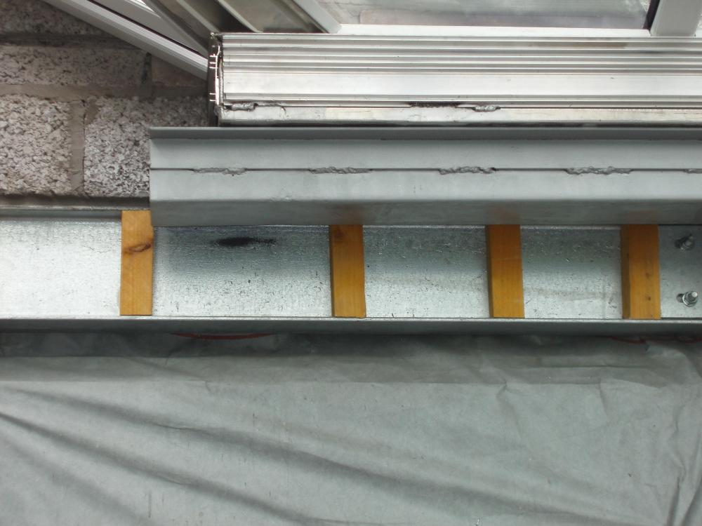
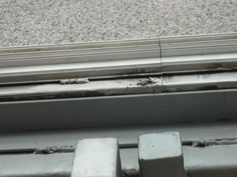
The good the bad / ugly? Here are some photos from a project that is covered by one of the major home warranty providers.. who have been arguing for some time that there is nothing wrong with the welding. The steels and aluminium sections you see are holding up a substantial glazed structure subject to snow drift loading in addition to the run of the mill design loads. I think I may have shot myself in the foot earlier by extolling the virtues of CE marking...but there are benefits. The fabricator who did the work claimed they were CE marked but on investigation it turned out that they used to be under their old company before they went bust. Anyway, some key points are: try and avoid site welding unless you have access to a real pro who can over head weld etc. Believe it or not the “goodish” and the “ugly” work was carried out by the same firm.. I cannot explain.. If this sparks some interest then I’ll try if I can post a blog on what to look out for if you are self builder looking to buy and get some steel fabricated and some practical tips I know of to get best bang for your buck and so on. As always if anyone feels free please comment. The "goodish" Not a bad end plate weld on the box section, it is covered with a galv finish though.. seen worse. Oh dear going downhill! And now we are somewhere else.. how do you classify the quality of the weld when it is kind of not there?
- 29 replies
-
- 1
-

-
- steel fabrication
- steel
- (and 3 more)
-
Yes, if for example you are on reasonable rock. In this case the found will not be a traditional strip, almost like a "skin" of concrete. For all, if you have a taller structure on a small foot print, introduce large areas of glazing etc on the ground floor you often find that when the wind blows it wants to "topple" the structure. To deal with this you need to design your piles to not just carry the downwards load but also to resist uplift and that can add to the piling cost as the piles need to work in both directions.. up and down. If you do have a site with rock close to the surface you may also find that BC still ask for the founds to have frost cover (min 450mm) and thus for the unwary you then spend a fortune on a pecker carving a hole in the rock just to fill it in with concrete. There is often a more economic way to do this than just blindly following the regs regarding foundation depth.
-
Two different points of view here. I can see both sides of the equation. On the one hand you have folk that have welding certificates (grandfathers rights) and loads of experience, play by the rules. On the other you have those that don't. For example you may get a price for box a section fabricated steel frame. There are two types of box section.. cold formed and hot finished.. they are two different animals but there are very few folk that know how to distinguish between the two. This is can be a big safety issue.. you find that the cowboys often substitute a cold formed section for a hot finished one as they (cold formed) are cheeper.. and that is where the trouble can start. It's also to do with the provenance of the material. I have surveyed buildings for extension and found some really odd steel sections. Turns out that these were basically fakes from elsewhere, they look like BS sections but when you put the mircometer on them the flanges are thinner! Then you have the quality of the steel to contend with. So yes, on one hand it seems like we are "controlled" but on the other this scheme has gone a long way towards improving safety. Make no mistake.. there can be a big difference between the person (and the conditions they do it under..factory or out in the rain) that welds up your garden gate from the one that welds up the end plate (with the associated quality control) on your steel beams which could be carrying literally tonnes of load! I would happily go back to the "old days" but you can't turn back the clock. Remember that modern design aims to be more economic.. thinner and lighter steel sections... less margin for error / material quality To achieve more economic design you need to have tighter control on the quality of the material and welding process, the bolts, the actual steel erection, grouting of base plates etc.
- 29 replies
-
- 1
-
-
- steel fabrication
- steel
- (and 3 more)
-
Just a thought. One of the best ways to approach this is to start with the basics. Always check, then double check the obvious to make absolutely sure, then you can proceed with confidence. Have you looked under the floor if suspended? .. have you checked your roof, gutters, rain water pipes and drains to make sure all is in order. If you have neighbours in close proximity..have they been up to anything? If you have only done this once then do it a second time! For older structures in particular drafts are good, that is partly why they last so long. What you are looking to do is to maintain ventilation while at the same time introduce insulation.. and as each house is different, like a vintage car you need to get a feel for your own home and work from there. Remember that often you won't be the first to have tinkered with the structure! Look outside. Do you have a locally variable water table, have big trees been cut down? Big trees can also take a lot of water out the ground in the summer when it's warm so removal can result in a lifting of the water table locally thus in warm weather this may manifest as high humidity. And to state the obvious look at the ground levels and what the ground surface comprises, the falls away from the house and so on. For all. Although Benjseb has a period house this applies to all investigation. It's best to really get a handle on these basics before you start spending a fortune of ripping out walls / changing insulation and so on. If you don't, you run the risk of just transferring the problem somewhere else. Benjseb.. Another key to this is to be patient with the old house.. the best way if you have time to is to make a change and see what happens..
-
Hi Adam. @AdamJ Thanks Gus, I take your point that a whole life assessment including transport and disposal would be better. I agree, though I don't know yet how to factor those two additions in easily. As SteamyTea said, the ICE database does include some transport emissions. The authors say the database has a "cradle to (factory) gate" scope, covering modules A1 to A3 in the EN 15978 standard. A1 Is the extraction of the raw materials, A2 is the transport to the manufacturing site, and A3 is manufacturing. To be more comprehensive, I should then add in transport from the manufacturing location to my site, and energy I use on site in building with those products. I'd want to have a rough idea on how large a proportion transport-to-site emissions are before putting a lot of time in comparing so many different systems. I don't have any idea how to estimate the end of life emissions! I do know that the a lot of the neighbouring buildings to my site were built around 1880-1890, and then another lot around 1960, so are between 60 and 130 years old. I hope my house lasts at least as long (longer because it will be such a good house! ) I would love to believe that SteamyTea's 500 year statistic will apply to my house. Even if it only lasts 60 years, the decision on how to dispose of the house at at the end of its life will likely fall to someone else, but I could design it so the parts could be easily re-used. If I was designing it for re-use, though, I might be looking at using steel beams and columns and pre-cast concrete planks, because these are most easily re-used in new construction projects, from what I understand. Again, before embarking on a comparison between end-of-life emissions on multiple systems I would want to find out what sort of proportion of the whole they make up. Can you give me a rough idea? Adam I think you are doing a sterling job here exploring this complex issue. You asked "..Again, before embarking on a comparison between end-of-life emissions on multiple systems I would want to find out what sort of proportion of the whole they make up. Can you give me a rough idea? " I wish I could! A bit off topic..life span of your house. For all, when the loadings are calculated for your house they are based on the probability of occurrence. Take the wind loading, (an environmental load) here we often base this on a return period of 50 years and design for that and when you apply for a mortgage the lender works on a similar probability to ensure their asset is protected. However, we know that timber framed buildings last a lot longer than that, hundreds of years, often it's fire that ends their life. I can't see for example how a modern timber framed house cannot also last well beyond the " design life" if it is well maintained. Turning back to fact that I can't answer your question! Modelling is often an intrinsic part of modern development and the build process. Structural Engineering has benefitted from this, the computer models are significantly more advance even compared with 5 or 10 years ago and this continues as the processing power of computers grows at an exponential rate. But as we know predicting the future and how the materials we use now can be recycled later is difficult to say the least. This uncertainty can throw any model right off. Also, these modern models generate a huge amount of data that needs to be stored.. and that uses electricity, I try and avoid thinking about how much electricity data storage requires. The energy requirement for this may well increase as we start to gather real time data on home automation for example. But at the moment this is one cost of innovation and this will pay dividends in the future. As an aside. A colleague who works in the oil and gas industry recounts hearsay where they were analysing the all up loads / stresses on a rig using FE analysis. The output was a bit on the red side and they felt that as the client was not an Engineer they may have a concern as there was a lot of red on the model. Someone joking said, just change the colour palate on the graphics... the same can apply to the carbon model. At the back of my mind when I was posting on this was.. What if you are on a limited budget, first time self builder say but want to do the best for the environment. We know that for example the latest technology.. some batteries, circuit boards, complex systems often have rare earth metals in their construction. It's reported that there is growing activity relating to mining of the seas for these elements and we intrinsically know that this is probably not good for the planet. To be clear, I'm certainly not suggesting that we should abandon innovation. But if you are on a budget maybe select the materials that we already know are not too bad for the environment.. sheep's wool insulation, straw as a good example, although timber , steel etc are already proven to be easily recovered and recycled. Lastly another way you can also protect the environment is to spend the time getting the quality of your build up to scratch, good detailing and workmanship to keep the weather out and so on. A well slated roof can last for over a hundered years if properly done, a bad one much less. I do wonder when you see the complaints that are raised against new build how much of a carbon cost is attaching to shoddy building practices and workmanship. Keep posting AdamJ and thanks again for sharing.



