


Gus Potter
-
Posts
2383 -
Joined
-
Last visited
-
Days Won
34
Everything posted by Gus Potter
-
Hiya. Yes if you can post some drawings then folk will chip in with value added comments. The main thing is to post so folk can see the roof space, plan view and sections and where the load bearing walls are below. You probably have plenty options but to get some practical SE type input then the drawings are required. Also let folk know if this is your "forever home". There is probably lots you can do at this stage so now is the time! maybe?
-
And there lies a potential problem. That is a big opening. When the wind blows on the glass the frame around about need to resist the loads. The central pane of glass is vertically spanning. The bottom rail prevents it from moving in and out. At the top there is a gap and the fixings are subject to a lot more bending force. For fixings to realise thieir full capacity they also develop a "second order" tension effect. They can't develop the tension as the compriband compresses and the frame at the top will bend upwards / twist under wind loading. One thing that stops the movement and saves the glazing companies is that the plaster board, masonry check outside / or the mastic lasts just long enough to make it very difficult for the home owner to complain. Bifold doors can be even worse as when they are open they rely on the top part of the frame to stay rigid, it does not have to be windy to cause a problem. It's a dilemma once you start to delve into it!
-
Airtightness - Parge Coat vs Airtight Paint
Gus Potter replied to Johnny Jekyll's topic in Heat Insulation
Nod.. see when you are sticking on the external corner beads for rough cast do you mix in a bit of old gypsum plaster to flash set the dabs on the beads? -
No, whether they barrow it in or pump it the final result will depend on the quality of the mix design, the weather and internal temperature on the day, good compaction and a dilligent workforce. These are the things to focus on. Oh and in the old days you they used to say.. don't buy a car made on a Monday of Friday as folk were still hung over on a Monday and wanted to go to the pub on Friday.. corners were cut.
-
Is it veneered door? The discolouration could be due to this.. where the veneer has caught a bit of the sap wood. Or something to do with the glue type?
-
Airtight walls & fixing stuff to them
Gus Potter replied to WWilts's topic in New House & Self Build Design
Just a thought.. well a couple. SBR is not the same as PVA and they behave in different ways. If you let SBR dry then stuff has less of tendency to stick to it. You can make things worse. SBR is generally meant to be left until it gets tacky then you apply gypsum based or other cementitious materail to it so it forms a chemical bond. Have a look at the SBT technical data sheet before using it to be safe. It's on another thread but the "green plastic" has it's benefits provided you get the rest of the details right and control the quality of the whole job. Up here in Jockland if you turn up to say a domestic loft conversion and ask where are the tapes are they (the Contractor) may suggest you need a deep fried mars bar to rewire your brain. Maybe they do the same in Yorkshire? For all. If you are getting your local builders to price this kind of stuff then be mindful that complex air tighness comes at a cost. If you are new to self build or extending start with the simple stupid, the things you can be comfortable with and able to control quality wise yourself on site. Make it as simple as you can even if seems initially like a comrpomise. Once you get the prices back, if you get many at all, then consider where the weak spots are.. service penetrations, the real howlers.. movement in the structure as it beds in.. can easily be 10 - 15mm and so on if you want good long lasting air tightness. If your aim is just to get a good result at the beginning then why bother going to all the hassle? -
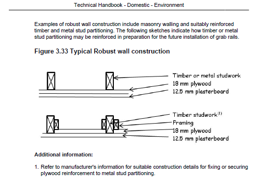
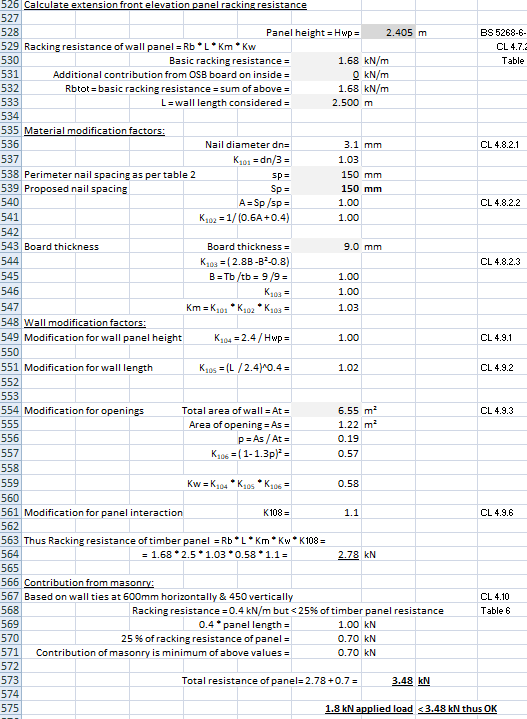
Hiya. Hope this helps and for a bit of fun (please excuse my grammer / spelling) I have added in some other stuff later to do with timber framed structures and thickness of ply / OSB boards in a structural context. Internally.. towel rails.. future provision for grab rails in bathrooms etc. The Scottish Building Standards talk about robust details. Below is a screenshot from clause 3.12.3 from the domestic handbook. 18mm ply is considered to be robust. Next turning to timber frame and what the structural sheeting does. Your vertical timbers generally hold up load. But at the top and bottom they are often just nailed with 2 to 4 nails to the top and bottom rail. Thus if you put up a TF panel with no sheeting it's easy for the wind say to push it sideways.. your house will then fall over. If you nail a sheet of ply to the frame it stiffens it all up. The sideways (horizontal forces are transferred from the timbers through the nails and into the sheet. The sheet then transfers these loads to another part of the sheet that is connected via other nails at the bottom say and back into the timbers. The sheet acts like an exoskeleton. SE's call this diaphragm action. The nails carry mainly shear ( sideways loading), they do other thinks but I'll leave that out for now. Now remember where the load goes. From the timber, into the nails, into the sheet, into other nails and back into the timber. Now if the sheet is thin it will buckle and also fail where the nails are transferring the shear loads. To mitigate we can make the sheet thicker.. thus spreading the shear loads at the nailed connection. Below is a screen shot of part of a TF panel design, one I made earlier today in the oven. Its a bit abbreviated and there are some post and later calcs that go with it. Also I have manipulated the calcs to suit this panel so please don't do this at home. If you are browsing then please don't read on. If keen then the following is a fly through to give you a flavour of what it is all about and the things you need to look out for. The above is based on BS 5268.. it's a bit less lengthy than the Eurocodes. Rows 529 to 533 are the basic parmeters showing the basic strength of a typical TF panel. You can see here that you can add another sheet of structural board on the inside. Row 531. We do this if we get stuck.. BH members like to put big holes in walls and fill them with glass. Now we take the basic strength and start to modify it depending on the following: Row 536 to 541. Here we are looking at the spacing and diameter of the nails. Be aware the nails and spacing are important! At row 543 we take into account the board thickness. The base line for this code is a 9.0mm thick sheet. if we make it thicker we get a positive increase in resistance. Rows 549 to 551 take into acount the shape of the panel. A long low one will carry more horizontal load than a tall thin one. Row 554 takes into account the size of the windows / doors. Cut openings in the panel and it get weaker. Row 561 looks simplistically how many other panels are attaching.. this requires an essay / book to explain. Row 566 recognises that the TF and masonry interact. Row 575.. if the applied load is less than the resistanc we crack open a beer! Lastly you'll see that this panel appears to be over designed. It's not as the later checks on global stabilty are the critical ones.
-
@Rebel80Good to see the slender vertical glazing bars. They look great. They look like true sliders rather than the lift and slide type. We have the Origin ones and they run pretty smoothly with similar sized panels. The locks are discreate as are your's. Like them. I think the break in the bottom rail is a potential issue. Your building is going to move under that bottom rail. You need to make sure that the drainage track channels the water outwards.. that's not going to happen once that joint opens up and translates sideways. Also as they are true bottom sliders you'll notice the bump as the bearings run over the gap in the stainless running bead. I have found ours are really sensitive and even a small amount of dirt on the running bead is noticeable. If these beads come out of alignment on plan then you'll be even more disapponted to say the least. If it was me I would be minded to ask why did they not put the joint under the centre pane and fit a coupling piece under to ensure the water is channeled outwards at all times. The track will attract a lot of water when you get some driving rain against the glass. Interesting to see your steel over. Who designed this? I wonder what is above in terms of load? The packers over the head look tight on that span particularly over the fixed centre pane. I ask as am curious how the installers have managed the deflection in the centre of the opening.
-
Frameless glass windows - my design.
Gus Potter replied to Caversham Build's topic in New House & Self Build Design
Sleep well! You probably have enough masonry over the opening and to each side to form a properly butressed arch. Thus if you "very conservatively" project a 60 deg line up from the edge of the opening you form a triangle of masonry. This is the bit the steel needs to carry. If say brick and the perp ends (the vertical joint at the end of the brick) are fully filled then it will almost be self supporting over a small opening width. @Caversham Build"I also have a 6mm plate welded to the underside of a cantilever beam beam to support around 100 - 150kg of masonry over a span of 4 m " Cantilevers are a very different animal as are top bottom plates welded to beams as they can introduce significant buckling effects and torsion (twisting) effects respectively. It's a long explanation but if you have any concerns don't hesitate to raise this with the SE. -
Yes, have seen this myself Nod. Have seen a couple where you can actually wring the water out of the insulation into a bucket. But when you investigate further you often find that this is a symptom of a problem that lies else where. For example, water vapour is getting in round the sides, leaky pipes, sparly ducting conduits sloping back into the wall.. it's a long list. Also take a timber frame, if the trickle vents to the cavity are blocked then the moisture is more trapped. Sometimes the breathable membrane is installed to wrong way round.. ! Yes designers are aware of the risks and in the short term if you let the building breathe both ways then it will probably have more of a chance except in say family bathrooms or in heavily used kitchens. Probably the stir fry is you friend as the grease will seal the gaps? Interesting you cobservations. Yes, this cropped up a couple + decades ago when timber frame really caught on in Scotland but at that time while we knew about the "reverse dew point" we discounted it as a serious threat. Now however the insulation levels are significantly increased and air tightness is now a consideration. In the early days we got away with it as although the timber frame houses were comparitively much warmer than the existing housing stock they were still draughtyish compared with what we are building now. But even back then we know that the more insulation you introduced and the more you controlled the air flow then an increased risk of condensation would follow as a consequence.
-
Plus one to the above. There are few nautical folk on BH. A lecturer of mine used to use this term when he was teaching us about how to find a solution that initially seems very complex and unachievable. You point your boat to a position you know you can get to, then when there, complete the last leg. He actually explained how this was a good commercial approach at times as if we wanted to get a job we needed to know that money does not grow on trees. If self building is at the top of your list then can you move / rent in your preferred area? Keep you ears to the ground and mix locally. Maybe try and cut you teeth on a small renovation, make some builders contacts, you may find something falls into your lap... that is my attempt at aiming off. All the best and keep posting.
-
Frameless glass windows - my design.
Gus Potter replied to Caversham Build's topic in New House & Self Build Design
Like the idea. But trying to mount glass almost directly into brick, drain it etc at the base is as others have pointed out fraught with potential issues. The brick line will vary a lot more than you think. If you get a slender frame then on the inside can you mount slip bricks on a carrier and discertely fix. This way you can unscrew the slip bricks on the carrier to access the frame should the unit fail or just need maintenance. @Onoff.. has had a go at this re his gate posts so you may get some ideas from his posts. Ah! Have seen windows with 10 year guarentee but the sealed units only 7.. in the fine print. It's a mine field this.. once you delve deep into the standards etc. One basic rule is that sealed units are not tested for any standing water at the base, that is why packing and drainage is vital if you want to make a case for replacement. I think that unless you get the detail right you'll be lucky to get a couple of years out the sealed units. In terms of your lintel a 6.0mm thick plate is not going to cut the mustard. If you have plenty masonry above and it develops an arch then I would go for a 15mm thick S275 galvanised steel plate as a kick off., maybe 20 thk. You can look at stainless steel but the prices at the moment are bonkers. for stainless flats this thick. -
@Kernow It's a tricky one this. Lots of alternative views from the likes of @Radian, @nod, @MikeSharp01 and others. Nod, had a chuckle about the million pound houses.... For me, if you are aiming for a quality build then using the green plastic is a good backstop to guard against the odd bit of poor quality workmanship. It's relatively cheep and quick to install. Going back to basics. The idea is to stop the water vapour (a gas) from inside the house entering the fabric and turning into a liquid at some point within the depth of the construction, when it does this is often called the dew point. Water gas does no harm, it's when it turns into a liquid (manifests as condensation) form that the problems arise. Now most insulated plaster boards you see now are vapour checked.. they have a built in bit of material (could be a metal foil) that serves as the green plastic. Now these sheets have joints that can be taped and sealed.. all good .. until you get on site and the sheets don't get cut perfectly. Usually the place where they don't get cut right is high up and on angles.. just the place where the air is warm and humid. Warm humid air has lots of water gas in it and this gas wants to migrate to areas where the humidity is less for example, just like a tea bag in a cup, it want's to diffuse. Also buildings move about so while all may be good for the first few months once the building dries and moves your joints may not be quite so well sealed. SE's for example often design for 10 - 20 mm movement on a timber frame house! You plaster board is connected to the underlying structure. Motto here is check the fine print on your moisture control spec, installation tolerances etc when buying the insulated plasterboard. The green plastic is quite "stretchy" so that is a good property compared with your tricky "sellotaped" joints. For me, for a qualty build where you risk moisture condensing near timber or other water sensitive materials I would stick a bit of green plastic under the insulated plaster board as a secondary barrier to prevent water vapour entering the timber structural zone. You have to be sure that you building is able to effectively breathe outwards everywhere! If not you will have problems. It's not common but you do get a reverse effect sometimes in the UK where the inside of the house is cooler and dryer than the outside. This happens after a cold spell where the house cooler and dry.. then a warm weather front blows in carrying lots of water gas. The warm humid air tries to enter your house and you get a dew point in reverse. It does happen but not often enough to be a major issue in general.. but Radian point this out.
-
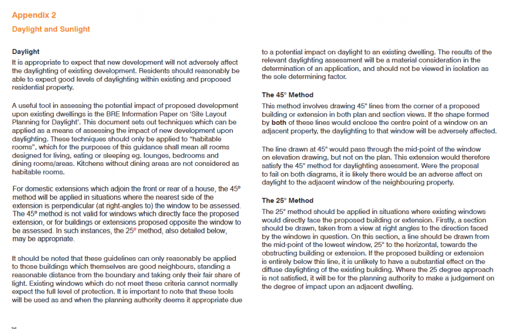
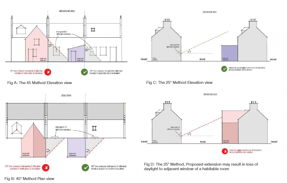
What a minefield! To compicate matters the right to light is different in Scotland and also complex. I don't know but it may also be different in Northern Ireland? If in Scotland your starting point is to get a handle on on how your building may overshaddow your neighbours and thus restrict their light. That said there are some common principles that are worth getting you head around first. Below is some typical householder development guidance offered in Scotland with some handy diagrams. Now although the houses shown below are attached in the spirit of the guidance this could also apply if you say had a pend between the two houses.. or a balcony serving one dwelling but attaching to the next house. To my mind even if there is a gap between the houses the same rules apply as a starting point for overshaddowing etc in Scotland.
-
Brilliant! Well done.. you have conveyed the info, doesn't matter what tools you use to do it. @CotswoldDoItUpper "Seeing everyone’s opinion come together to help guide design is great. " Yes it's good fun and enjoyable. @Selfbuildnewbie Looking ahead with an SE hat on. What you have looks doable without spending loads on money on a structural stability scheme that often gets hidden at the end of the day. You may just need some extra structure to prevent the building moving sideways along the rear elevation on the ground floor. Much will depend on where you are in the country, the elevation and method of construction. Keep aside an extra 5k for this for now just in case. If you don't use it then I'm sure you will still find use for the spare cash. Funnily in terms of the stair alone I think option one is best for highlighting a feature stair. Option two gives you plenty floor space.. but with a hall that size you could put some furniture in to compliment the pictures on the walls and decor say.. with a big hall you can make it appear like another room but still maintain plenty circulation space, diffuse and direct light. Option one would allow you to explore this as you could put a seat and coat stand on the left of the front door. Don't rule out using the hall as another "quasi" reception room. The great thing about a big hall is by changing the pictures, furniture and a tweak of the lighting you can easily change the first impression when you enter the house. Houses are for playing with as you grow older, not just for xmas!
-
Charlie.. you know your stuff.. was just teasing. But yes the windows need some work and the massing is not just quite right..but my glasses are dirty tonight. I can't put my finger on it at the moment. @Selfbuildnewbie A few first thoughts. The entrance hall could maybe be improved. When you come in the front door you have to go almost through a corridor of doors to enter the main core of the house which is the stair. The other thing for me is that you have a clear sightline right through the house to the French doors in the kitchen. I would seek to emphasise the size of the house (the length from front to back) As you come in the front door you have this storage space to your left, a blank wall to your immediate right and then a shower room. Not very exciting. What about shifting this storage space to the left side (east side) of the music room and making it a feature. Now you place double say glass doors to the music room almost as soon as you come in the front door (to your left) with diffuse light coming into the hall. The idea is that you use what we call false perspective.. the perceived space widens as you come in the front door making the house seem even bigger and longer front to back. The cupboard off the living room is small and with a bit of thought you can probably shift it somewhere else. You would make the opening through to the kitchen diner wider still. This would empahsise the stair. You could make the stair a little wider / grander. Once you get this bit sorted you can then look upstairs. It's not easy to do but there will be loads of folk here that will chip in to help you make an informed choice. All the best.
-
Hiya @selfbuildnewbie Good post and you have indicated the orientation. Not sure about having the store on the front elevation. Here is a thing. Folk on Build hub have an eye on the cost. Architect's say just don't put gridlines on their early concept drawings. It's bonkers as they also leave out critical dimensions so it is really hard to see how the walls line up between the floors. I have been doing this for a while and most Client's appreciate it.. it makes it so much easier to have a discussion. If you can, try and put some gridlines on your drawings and see if it helps you locate things in your mind. Charlie.. philistine here but is lopp sided not a indicator of art and crafts influence?
-
Great thread this.. much to ponder. There is no easy answer / the perfect solution. Having worked on the odd old building and converted steadings over the years while keeping up with modern approaches, new materials etc I'm often led back to first principles, practicality in terms of analysis (thermal performance in the real world) , keeping the cost down ( labour costs low = easy detailing for example) and to look ahead at future maintenance and how easy it would be to rectify an issue locally without trashing large areas of walls and the associated disruption. For me the starting point is always to look outside first. Here is a list of some of the things I like to gather info on. Ground levels, soil drainage at the base of the wall, the pointing.. the shape of the pointing on a brick / stone wall is vitally important and that if rendered then the type of render, general condition, drips on window and door cill details are examined as are flashings and anything else I can think of. For old buildings like saveasteadings the gable detail / cope and skew putts for example all need careful examination as do any chimneys an old flues. For @bighouseproblems the type of brick / it's porosity and mortar are of particular interest. Other things worth a look at are the aspect of the building, how sheltered is it from the drying / cooling effects of the wind, is it over shaddowed and where in the UK is it located..altitude and distance to the coast, the realtive humidity can often be a significant driver in a coastal location. each wall will behave differently so for economy / simplicity you are seeking a reasonable compromise. Yes, you can run computer models.. SEs for example use some complex finite element analysis.. but that is (hopefully) always coupled with common sense, reasoned judgement and appreciation of the limitations of the computer model. The same applies here.. any say computer analysis is only one part of the puzzle that helps you make an informed judgement. In general for walls above ground I'm not a fan of sticking any butuminous or water proof stuff to the inside of the walls like render. Not a fan of chemical damp courses or other gizmos. The idea of the warm batten is good in principle but.. you often have cross walls that form an integral part of the sturctural stability system of the building so you need to detail for that. Already it is getting more tricky. While on paper you can make a blank wall work the problems always seem to crop up in say the corners! To make it work you will need to detail well.. and live in the builders trousers for a while so you can keep an eye on their every move! Practically my first port of call would be to maintain a cavity between the external wall and your inner insulated envelope. You can essentially build a non load bearing stud partition. The studs can be fairly slender. You can bracket them mid height with plastic angle brackets to take the bounce out of the wall.. if you want to get carried away and are worried about metal brackets causing a repeating cold bridge. Next you can insulate beteween the studs with insulated plaster board over to prevent ghosting and to boost the insulation effect. Ghosting often happens particularly in kitchens. The studs are a little cooler so the fat condenses here and so does some of the moisture. This manifests as darker shading in your wall finish. Now this all may sound like something out of the dark ages until you get a price from the builder to install and stick to the inevitable complex detail. If a problem occurs, usually under / over a window or in the corner then its often much easier to access an independant non load bearing frame than some other options. Now in many cases you can introduce controlled trickle ventilation to the cavity in old buildings.. it needs some thought but often achievable. I would encourage examining the simple stupid option in the round, cost this and then if you want to get more innovative at least you have a bench mark to work with.
-
What's you gut common sense telling you? If you have lots of west facing glazing then overheating is a significant risk. If you are trying to shave a bit of the capacity of the heating system to deliver / make savings.. then.. if you have kids the doors get opened and left opened! Teenagers tend to open a window to have a fag or throw up out of them after socialising, you may too! Lastly remember that from time to time we may get 15 -20 deg Celcius.. would be a shame if this happened at Xmas when you have all the family round and you can't warm the house up for those who are frail say. Seriously though North light glazing is a cracking concept particularly if you are say a painter..or the like.
-
Hi Charlie. I started out nearly four decades ago, cut my baby teeth on the contracting side and when I was about 40 went back to uni to get the qualifications and experience I needed to handle structural design, reason being that I could see a way where I could become a designer. I had got fed up building other folks ideas. For me I think design is holistic. You could equally start out as an Architect and become say an SE if you wanted to say perfect the art form of exposed structures or, you could specialise in other areas that say relate to environmental / civic structures, dams for example. I now make a living working for myself as a designer, mainly now in the domestic market. It's a great job.. I wear many hats but there are enough Clients out there that pay me for my offering. For me one key (it has served me well) was to first recognise that the domestic market is very.. very much a people business. I have found that you need to spend a lot of time learning how to tease out what your Clients "need" as very often they have no idea what they do "need".. some have not actually sat down themselves and thought about.. how many kids are we going to have.. who is going to cut the grass, why do we want open plan when we need some quite space.. many many questions need to be asked. There is so much information to gather before you even start on thinking about the design. In fact is easy to to fall into the trap as a designer where you think. ah.. that is the design in the first few minutes.. that is an indicator of poor design and trouble ahead. Some Clients appear to have all the answers.. but you'll always find that just as in life folk can't think about it all. Some Clients are like this because they are nervous.. personality! It's up to you to understand this as it will serve you well later when evaluating how risk averse your Client may be. For all we often call this Client requirements and these can be sub divided not least into "hard" and "soft". The domestic market is very much different from the commercial market where you are often dealing with other professionals or people that are used to say running their own business and want say an extra steel shed to expand. Teasing out this information is a skill that takes time to perfect, you need to be able to build a rapport, sometimes you just can't so that is the time to walk away.. if you don't gell then the old expression is.. what is for you won't go by you. Once you get good at it then you can start to understand better what makes your Clients tick. Then it gets interesting as you start to think.. ok I am getting a feel for the Client's design boundaries, approach to risk and how they may think, the soft side. What do I have in my design tool box that I can start to introduce. What works for me is this. If you want to do great design that is of beauty, functional and is going to out last you then it all starts with the soft side and that first interaction with your Client. Before you start getting out the sketch pad ask the questions about how your Client lives just now.. empathise (takes time to learn) and they will tell you the rest with a bit of prompting. That has value.. trust is build and if you fee is a little higher than a competitor.. you'll often get the brief anyway. Charlie.. you mention vanity projects.. you are pushing at an open door here...
-
Up in Jockland here we have apparently sold off the wind rights to the sea bed for £700 million for off shore wind turbines.. and you think you have worries! For all.. who live south of say the border line on the map. Remember that although some in the southern end of our Island may want to get rid of the Scots.. the UK will lose about a third of the land mass if the "difficult" Scots bail out, and a huge area of current UK waters! Also, it could no longer be Great Britain as it will be "Smaller Britain" if that. Worth a thought. Fracking is another option but in the short term we need to be extracting as much as we can from the current assets we have to prevent short term volativity and fuel poverty. We have some complete bammers up here in the "Scottish Parliament" (glorified town council) .. so for BH members down south.. you may complain but try living up here.
-
Have you considered making an FOI (freedom of information) request. I can be a helpful tool. I have had a recent application stalled. The officer kept phoning me so I had nothing in writing, also was writing me fobbing off emails to cover themselves and stall. Spelled it out to them that I was going to make an FOI alongside making a formal complaint and want to see all the info including all the in house emails.. he said you won't get to see them all if any. I said that is exactly what I need as now I know where you are hiding stuff and where to concentrate my efforts. Two days later it's all sorted!
-
Insulating a pebbledash solid wall and damp concerns
Gus Potter replied to Ben Weston's topic in Heat Insulation
Just wondering.. Sounds like your extension may have lots of glazing for example so you are needing to do some compensatory U value calculations. Have you really looked at this in the round. It's an old house and to insulate the original walls is going to cost a lot and you'll loose gross internal floor area if you do something on the inside which could impact on the value of the house. It's also going to be pretty disruptive. I would have a good review of your strategy before committing to messing with the original walls. EWI sounds good.. but what about the rain water pipes, the apprearance of the eaves and roof overhang, the ingoes to the windows.. you could make your house look cheep and nasty from the outside? Now is the time to take a step back, really test your design approach, make sure you are doing the right thing before you commit. It may be that you need to go back and review the extension design. Reviews can be good as you may actually end up with something better! -
That site looks sweet! Sets a bench mark. But to burst your bubble no protective mushrooms on the top of the exposed rebar. On the hole take that as a compliment. For all. When you are digging strip foundations say in clay don't run round with a spade smoothing the sides.. you want them a bit rough so the concrete gets an extra key down the sides.. wierd but..
-
Nod.. I think this needs some qualification from you as could be confusing to new BH members. For me it's about making sure that folk do things in a safe way and don't encounter problems later if someone asks for verification that the founds are ok. Yes there are many practicalities when you get on site.. like bucket size. Often to change buckets and try and dig founds of different widths costs more in time and increases the setting out complexity.. ground is mucky stuff and the spray painting lines say can get lost in the heat / excitement of excavating and getting started. Yes on a large commercial job with all the technical/ setting out back up varying found types are doable. You don't want to be digging for Britain (you'll get the sack as a designer) but we are talking self build / local builders/ diy here and what is practical in this context.



