Gus Potter
-
Posts
2384 -
Joined
-
Last visited
-
Days Won
34
Everything posted by Gus Potter
-
Just a thought. Embodied carbon is one measure. AdamJ. Yes.. to make the best job of reducing your carbon foot print starts on the drawing board as you are doing. At some point you need to often dig a hole in the ground, cart muck away. Then you often need to pour some concrete, the sand/ aggregate requires transportation to the concrete plant, the cement takes a lot of energy to make it. You need to cart muck away and so on. You purchase PIR insulation.. oil based product, maybe concrete tiles, hard to avoid. Then at the end of the day the building has to some extent a limited life so someone has to dispose of all this and that carbon cost may well exceed the saving you may make during the lifespan of the building. Ideally you want to leave the site "just as you found it" It's fine crushing up an old block of concrete flats for recycled aggregate, but if you then cart the stuff fifty miles or more and sit with the wagon engine running in a traffic jamb / unload it on site / the operatives come to work in van to do this and so on then it kind of defeats the purpose? As an aside and ask.. look at how many houses are getting knocked down at the moment partly to do with the VAT system. Ideally and one expression, is to "walk softly and leave no footprint" that is what your house should do. So my view is that if you are carbon aware you may want to think about what you are leaving behind you and not just reducing your footprint when you are living in the house. Once you start to think about this then you can start to look at your basic structure. Take an ICF basement. That is often a big hole, lots of concrete and lots of oil based insulation product.. I'm not convinced that your air source heat pump etc will offset the overall carbon cost and the subsequent disposal cost.. or do we want to leave that disposal issue for the next generation to solve? yes you may save a bit on electricity during your occupancy and so on. I think that if you really want to make an impact then it's worth looking at the project in the whole, the carbon cost of construction.. fuel for wagons, concrete, insulation and so on. Then the carbon savings when you are living in the house, then the reduction in your carbon footprint at the end of life stage. When you weigh all this up you may find that you can save some money while also leaving significantly less of a carbon foot print overall. If you look at it this way then you may be able to afford carbon wise the extra odd luxury while making a positive contribution to the environment. Although this may sound cynical I have written this in the hope that BH members that want to self build with a limited budget, while doing the best for the environment may be encouraged to look at the whole of life carbon cost. It is not always necessary to buy the "latest" and usually expensive technology when you can skin the cat in another way. Self building can be a great journey, often folk move on, you can see it on BH.. lots of serial renovators and repeat self builders etc!
-
Davejura.. I suspect that you secretly you want it too!...but.. just and so on. I built a house with UF on both ground and upper floors, suspended solid timber joisted floor on both the ground floor and first floor. The first floor had the plaster board ceiling, 195 mm deep joists and 22mm chipboard, carpet on top. Glass wool between the joists 100 deep, netting over the top of the joists to which the UF pipes were attached to with bits of garden tie wire we cut up. The netting tended to hold the pipes up against the floor and surprisingly it all worked pretty well. Didn't destroy the carpet. It was all done on a shoe string budget a good 25 years ago. I still keep in touch with the folk that bought the house and it is all still working. With hindsight I would have gone for the plaster board ceiling, some 9.0mm thick OSB board on ledgers attached to the sides of the joists, with a lean mix screed encapsulating the pipes. This adds mass, thus sound protection and spreads the heat more. The down side at the time was that this extra load of the screed added to the cost of the joists so I took a chance. We know heat rises so keeping the bedrooms on the ground floor is a good idea as you know if you want a cooler bedroom to sleep in. All I would say is that at the concept design stage make an allowance for the extra weight of the screed when sizing your floor joists, keep your options open, at the very least if you don't at the end of the day go for a heavy screed then you'll still have a good stiff, non bouncy floor. Oh, and the West of Scotland is a great place to live. All the best
-
Thanks to all for contributing to this post, every day is a school day, much appreciated by me! Nod and many others are making great practical points so thanks. A bit off topic. The flat plate I think comes in handy when your boards go over the standard 2.4 m as the flat plate acts a bit like a noggin (dwang) and supports the horizontal plaster board joint so you don't get a crack in the finish. Again turning back to Nod. Similar cold formed sections can be used to create load bearing walls too and here the noggings etc often start to play a structural role. I don't know if anyone has posted on BH about a fully cold steel formed structure ( external frame + internal racking / load bearing walls) but I'll hazzard a guess that Nod and others have worked on them. Once walls become load bearing then the flat plate can start to form part of the fire protection. The white book as you can see above and the "site book", see internet, provide some great info and the real practical tips you will get from the likes of Nod etc.
-
That is some house.. no wonder you are excited. I wonder what the views are you'll have. Setting aside the Architectural scheme. At first glance there are a good few opportunities here to explore in terms of structural design particularly on the rear elevation in terms of sideways horizontal) stability of the building. The corner windows on the rear elevation? Frameless glass (cantilevers?), corner posts or hanging from the roof structure..? You have that large area of glazing on the rear elevation coupled with a partial basement.. in Engineering terms it sparks interest. what is the ground like.. will there be significant differential settlement.. if so how much and if realised how do you deal with that while not compromising on the Architectural design intent.. The form of construction; steel frame, timber frame, traditional masonry or some hybrid with ICF basement.. so many opportunities / options! All the best. Look forward to seeing how this develops.
-
As with all drawings; planning applications, BC drawings (warrant drawings in Scotland) you are seeking to convey information. Adding photgraphs to your drawings can be help the planners etc to visualise what they are being asked to assess, it may even help speed up your application! If you are going to add photographs then I would put them on perhaps the elevation drawings rather than the site location or block plan. In Scotland for the last few months (COVID) some of the planners are / were not making site visits so providing photos can help in my view mitigate some requests for extra information.
-
Gus’ Structural Engineering and DIY Part 02
Gus Potter commented on Gus Potter's blog entry in Gus Potter
@Mr PunterYes usually with standard scaffold poles which have an outside diameter of ~48.3mm. The top part of the prop (inner tube) is the same diameter as the scaffold tube so you can make 90 degree connections with a standard double coupler, angled (diagonal bracing) connections with a standard swivel coupler. The outer tube of the prop has a diameter of ~60.3mm so here you use reduction couplers. -
Gus’ Structural Engineering and DIY Part 02
Gus Potter commented on Gus Potter's blog entry in Gus Potter
Hi Jilly. @JillyYes, you can do your own structural calculations and submit them for your own extension but you should be competent. There are other factors worth some discussion. Here are a couple. The first is to recognise that Building control will make reasonable checks to satisfy themselves that the design meets the Building regulation requirements. For example, they may check 10% of the maths in the calculations and look at perhaps the stability system. However, it is the responsibility of those carrying out the work to ensure that the provisions of the regulations are met in full. You could look it another way. If BC were responsible for the design then there would be less of a requirement for an SE say to hold the level of PI cover that they do. Secondly, if you do your own calculations and something goes wrong where do you stand from an insurance point of view? I would recommend that if you are going to do your own calculations then it’s worth having a discussion with your insurer. Before you start. -
Acrow props – is there an alternative that won’t fall down? Yes there is in some cases. Much depends on your programme, whether you wish to give it a go yourself and how much time you have on your hands. Please feel free to comment / question. I’ll answer if I can (if not, I hope some other BH members will be able to) and provide more detail. Photo 07 showing holes for the needles and the first few temporary works studs going in. The base of the studs are sitting on a sole plate fixed down to a temporary strip foundation. Part of the sub floor has been built up and concreted to provide a working platform. Photo 04 (copied from previous post) In my case I have been dipping in and out of our project. I reckoned that I would need some 25 – 30 Acrow props for the temporary works which would take me about 4- 6 months as I was also mucking about with other bits of the build. To hire 25 props at £ 5.00 per week = £ 125 per week! I could have bought the props but I would have needed to get rid of them after in my case, just gave up on that. I have two or three old props that were used to help tighten up (pre load / stress) the timber propping. The timbers 145 x 45 (grade C24) to form the needles studs, top and bottom sole cost ~ £350.00 ex vat plus a few screws (about 250 number 5 x 80 gold screws I think) to fix things together. I knew that I could recycle the temporary studs to form a new floor we needed and that if I cut back the needles I could also use these to prevent the top steels from moving sideways. This is called simplistically “ lateral restraint”. Also, I used same needles to provide additional what is called “torsional” restraint to the top beam , a slightly different effect, but is it to do with the fact that I used one beam with a top plate to support both the inner and out leaf of masonry which can be loaded in different ways at different times. These different loading patterns cause an uneven loading on the top of a single beam.. resulting in a twisting (torsional) effect. You can see more photos in post 01. Fig A 01 showing proposed rear elevation. How does it work / stay up? The starting point here is to calculate the amount of load. With this house the roof spans front to rear, the attic is full of stuff, the walls are rendered brick cavity walls and you have part of the weight of the new extension roof that is now attached / built into the outer leaf of the house. Once you calculate this you end up with a working load you need to hold up of round about 25 kN/m run of wall. Approximately 1.0 kN (kilo Newton) is ~ 100kg so 25kN/m is about 2.5 tonnes per metre run of wall. Thus if you put your needles at 600mm centres then each cluster of needles has to carry 0.6 x 25 = 15 kN (1.5 tonnes) and the studs supporting the needles at each end need to carry a vertical load of roughly 0.5 x 15 = 7.5 kN (0.75 tonnes). These types of loadings are as about as much as you can “do” for this type of system. There are other ways but you need more height for timber needles. To make life a bit more difficult the window lintels on the first floor cause the load from the roof to be unevenly distributed so some needles need to carry more load than others. You can see from the photos that some needles are in pairs, some are a cluster of three. In terms of the studs these needed doubling up in places and the whole lot horizontally braced at mid height with some diagonal bracing just to stiffen the whole lot up. While this sounds like a lot of work once you get going it’s actually quite quick. This approach is a little different from using Acrow props. With Acrows you wind up the prop to preload the system so that the upwards force is approximately equal to load the wall you are taking away is carrying. Aside, If you are Acrow propping things then be careful not to over tighten the props as you can easily start to lift parts of the house accidentally! Here, what I did was to use a combination of the spare props I had combined with timber wedges to pre stress the system, one set of needles at a time. The other thing is that over time the timber can shrink / creep a bit so I was careful to get the timber dry first and then monitor the system as I went along. All sounds complicated but once you grasp the principles a lot of it is common sense and this is not a reinvention of the wheel. I know a few old joiners and brickies that still remember doing this when they were serving their time. Some extra information that may help. As always, comments welcome. Options for beams- In terms of material vs labour cost it can sometimes be beneficial to design the steel beam as a single beam with top plate. The one you see here forms part of a double flat portal frame. You will also see designs that use a separate frame for the inner and outer leaf, a question of balance, each project is different. You can introduce a problematic thermal bridge at times if you deploy these single portal principles to an external wall, but in my case the steels are now internal.. the thermal bridging is resolved in the main. Propping considerations. Below is a screen shot of part of a temporary propping design for a set of 4.0m bifold doors etc. There was another big chunk of the rear wall to come away at the same time which is not shown. The contractor here was stopped from working until remedial action was implemented. Screenshot propping.docx Fig 02: The purple lines are the props and what is called the lacing / bracing system to stop sideways movement. Work was stopped when this was discovered. Part of the contractor’s defence was that “he was insured” Photo 08 Photo 09 A few points. The Contractor had not investigated the ground under the slab and the base of props can slide about. The site investigation had revealed this ground was very soft. Use of Strong Boy type supports at the head of the props.. these have a reduced load capacity and not suitable for the loads to be carried in this case. Props well out of plumb, no bracing.. further comments welcome. On a finishing note the timber propping scheme may look a bit rough but it was designed and executed with no unexpected movement. If this approach may suit you then as always check with or be a competent person. Thanks for reading.
-
Hi Grant. I'm not too far away from you, based in East Kilbride. Pity it did not work out with the builder. Don't worry too much about the steel that is encased in the concrete. For all, one way to look at this is as follows. For simple domestic stuff it's a bit of a rule of thumb. You'll often see that simple strip foundations have mesh in them. For foundations bearing on the soil the cover to the steel is often specified as being a minimum of 75mm. Roughly the first 25mm is to account for the fact that the machine you dig the found out with can't reasonably get closer than 25mm tolerance (much worse in real life) and pratically ~ 50mm is to account for a bit of the "nesting" of the reinforcement when you lap mesh etc and for soils that are a bit aggresive to concrete) it's all a bit vague. However, roughly the main thing is that is you have a good couple of inches of concrete round your steel and this protects the steel from corrosion for a good while. Grant.. you can see here that once the columns are embedded in the concrete pads that part of them will be ok. It's the little bit just above the top of the concrete that is a little more vulnerable. Practically, your Architect is in my view is on the right side of the argument.. but a key question may be.. will they take that on under their PI cover. The steels in the photos seem to have been reasonably primed , it's just that some of this seems to have been abraded at the bottom when the founds were poured. If push comes to shove then it's a question of examining how much if any of the steel is in direct contact with the soil, the soil type, how much is in the cavity and protected to some extent and how much on the inside is in contact with the inert fill under the floor. This information would be used to underpin an evidence based argument should someone (BC) query the view that the steels as they are good for the design life of the house. In terms of insulating the column. I can't quite see how the kit interfaces with the column but having a guess I would aim to get some good PIR insulation into the web on the outside, then for good measure foam any gaps in case it comes loose later. Here you are already starting to reduce the cold bridging. To make a proper job I think you still have to insulate on the inside but by filling the web on the outside you are going some way to avoiding making a rod for your back later. It would do no harm to keep the continuity of the kit breathable membrane running past the outside of the column as at the very least if you don't do this you'll be creating a weak spot in the vertical lap on the membrane. Much easier to just run it by and staple it to the timber kit each side of the flanges. One thing to look closely at is how the kit is fixed to the steels and plan that bit and the insulation / window details near the steels etc carefully. If you can post some section details so folk can see where the kit sits in relation to the steels you'll get some good positive responses.
-
Seems not.. pride comes before the fall and all that.
-
Hats off to all. Great "Columbo" work. Here is my go. Could it be the sampling chamber before all discharges in to the "Canal"
-
Hello Grant. That looks great, enjoyable to see folk embracing the portal frame principle. Good size house! You have two slightly types of portal as one seems to be creating a large volume, the other supporting a floor.. for the keen the two types of frame perform in different ways depending on the floor level. It kind of looks like a Scottish landscape the trees and grass, maybe Wales I don't know. And that leads me to the steel corrosion. I'll take stab in the dark here but it looks like you may have had some tree stub muncher in so it's hard to see the soil, but looking at the type of trees it may be that you have a shallow clay soil, a bit sandy maybe. If so the soil is likely to be a little acidic such that it promotes a little corrosion compared with a more alkali soil like limestone. I would have a look at the SE spec not just for the steel but also for the grade of concrete used under the ground. If the grade of concrete is high then that may indicate aggresive ground re corrosion potential.. ask your SE. If you are in Scotland then this steel protection should have been speced to get your Building Warrant and the Builder should have followed this specification. It may be that the the detailing is such that the steel is ok re corrosion. Interestingly @Jilly was posting about something similar recently. I would have a word with your SE, if the builder has deviated from the spec then discuss. There are often easy solutions to this.. sometimes you just need to re appraise and all is proved to be ok. The SE may say.. don't worry there is plenty sacraficial steel available to deal with the corrosion so cart on. They may say..mmm I don't know. In this case ask why then raise the possibilty of introducing some cathodic protection. You can find info on this on the web but it't just like protecting a boat from corrosion and it should not be horrifically expensive especially if you good wet clay soil.. There are members of this site that know about all about the physics of this. But simplistically (I think) you could just bury some lumps of zinc in the ground and electrically bond this to the frame, (check with the Electrician if need be so that what you are doing is compatible with their work) make a note to monitor every five years and get on with enjoying what looks like is going to be a great new home. Hopefully this is some reasurance.
-
Now we have got ball rolling. On off often makes a good point and boils things down. Always enjoy on off's responses. WWilts.. don't be put of the PM route. You may find the right one for you just drops in your lap! Gav_P you also hit it on the head.. good PM's (especially younger ones with family commitments etc) also tend to follow a route where they can be rewarded for their skills and this can often only happens on larger projects. It's a pity really as the small projects can be as equally challenging. There are some cracking big high value projects posted on BH but in general BH projects are much smaller. Up near Glasgow there is a huge amount of extensions ~ 20 - 80K going on and the say extra 10% for a PM (maybe with contract administration) cost is not what folk seem to want to bear. R_Sole has made some good posts about this, worth looking up in my view. Sole explains it in more technical depth. The contractor's push, cynically as they don't want to be supervised and so on. TBH the number of times that I see clients that could have saved more than the PM cost is remarkable. Architect's and SE's can often provide the same service at a similar rate. One good skill of a PM.. which takes a lot of experience is to get a client to recognise that if they spend too little the thing they think they are buying will not actually do what they want. But a good PM will get what they want at a fair price. I have copied a quote from Ruskin at the end of this post for all. But the market is such that all clients think they won't be the ones to be ripped off. It's only later when something goes wrong do they realise that it could have been different. What I have stated above is the "ideal" scenario" but the reality of life is that often folk think/ know they don't just have that spare cash to spend on the professional fees. In summary yes as a self builder extender you can cut out a lot of the professional fees but there is no free lunch.. you have to put in the work to realise these savings. If you are on a high salary say then the PM route may be best for you. Ruskin 1819 - 1900 “It’s unwise to pay too much, but it’s worse to pay too little. When you pay too much, you lose a little money – that’s all. When you pay too little, you sometimes lose everything, because the thing you bought was incapable of doing the thing it was bought to do. The common law of business balance prohibits paying a little and getting a lot – it can’t be done. If you deal with the lowest bidder, it is well to add something for the risk you run, and if you do that you will have enough to pay for something better.”
-
Hello WWilts. Good post.. I hope you are encouraged by the response you get here. If your are embarking on a domestic project then as strange as this may seem you have to like the PM as a person and that is a good place to start. If this a domestic project it is really important to get this off on the right foot. PM's are human too and professional PM's will invest in your project..think about it when they are "off duty" Find folk like that then start to look at the cv..often someone that is really invested can deliver great benefits even though on paper they may not have a mile long track record. They may have for example great contacts with builders. I know a few that used to be right hands on builders that are no longer able to make a living on the tools as they physically can't do it any more. But they know their stuff, almost like the poacher turned game keeper who is on your side. One trick is to seek them out as they tend to be in demand.
-
Hello Grant. Portal frames are handy things and quite versatile. There are quite a few ways of detailing these up to avoid the thermal bridging.. For all that may be less familiar with steel portals.. you also want to try and understand where condensation can occur and this can be a little more difficult to deal with when you interface TF with steelwork, particularly if it is a renovation / conversion. For all..one thing is to remember that steel is water proof so any condensate on the inside will not migrate outwards unlike on the TF where you have a breathable membrane on the sheeting ply for example. Once you get a handle on this you can then start to check and develop how you are going to try and fix things to the steel, the tricky bits often occur at the top and bottoms of the steels. You make progress.. then you go back and review the design.. and with renovations this can be quite an iterative process. If you want, post some more photos (panoramic views are helpful as it lets folk see what the steels are holding up and so on) and maybe a few cross sections from your drawings (if you have them) so folk can see how the TF is designed (or not) to interface with the steels. Just as an aside.. what is the white paint? for decor / corrosion control.. or fire? You'll get lot's of good ideas here as you know and one of these may just be the perfect solution for you; save you time and money etc.
-
Window fitting starts on Wednesday: Damp steels
Gus Potter replied to Jilly's topic in Windows & Glazing
Hello Jilly. Hope this helps. I have put my thoughts in line with your text and in italic. Update: I'm a bit stressed. ..I didn't get these replies until after the job was done and it was too late... Don't be, there is often more than one way of looking at things, and, you have all the resources of BH at your disposal. I chipped the cement off as best I could, cleaned the steel and painted with red oxide. Good approach but can see how you may still have a concern. However, the windows have been installed and there is a small leak at the bottom near this place, the fitters came back to seal again but its still leaking. They will come back (but Christmas is causing delays), and they are making an aluminium shroud for the outside. Maybe don't conflate the two things.. leaky windows with steel corrosion. Separate the two issues. I didn't realise about the bituminous paint thing (which the structural engineer specifies when you look through the detail). Yes they do as this is a common approach when you design / convert a farm building or an industrial building.. we know that this interface between the column, ground level, foundations and walls is a tricky area to detail. OMG, I can see this is my fault. Because there had been so many little problems with the builder I had decided to ask him to stop at the superstructure and I would go on to subbies, but this has left me wide open to making mistakes...like this. No Jilly it's not your fault. What you are doing in my view is exhibiting a good understanding of the build process, identifying previously unforseen problems before they really become an issue, which almost always occurs on renovations / conversions seeking advice, then a solution. As a further word of encouragement lots of companies would love (give their back teath) to have their graduate trainees exhibiting / questioning matters as you are doing. Is there some kind of desiccant that will dry this out? How can the steel be treated retrospectively?? Will BC make me take the windows out?? I hope the comments I have made above will give you some encouragement but now time for some substance! BC will accept a reasoned argument so no need to "take windows out" that is last resort stuff. But for all.. if you wind BC up then.. If any other members can chip in then thanks. Jilly as I said above. Don't conflate the two issues. Your windows and doors should be drained with small drainage channels and outlets. The amount of water that comes out these will be small but if these are not located / working correctly this is more likely to cause a problem with the glass rather than the steel. I'll leave this to the other members to comment on. I'll give up on the italic now. Turning now to the steel corrosion and the fact that this is a conversion. Often when you are renovating you have to take a pragmatic view. That post you have looks quite chunky. It also looks like an older type section. I suspect that the wall thickness of the post may be relatively quite substancial. The reason this matters is that the section can suffer quite a bit of corrosion before it becomes unable to carry the loads. Also, the corrosion that is happening is near the end of the section, this is where the bending forces caused by the wind and so on are less. Think of it as a ruler getting bent, the wind sucks the adjacent doors/ windows out, they are attached to the column and most of the movement / bending in this takes place in the middle.. the bending forces are greater here in the middle of the post. At the top and the bottom the column carries more vertical load (also shear load for the keen) but a locally thinner section here can often cope with this and in Jilly's case this thinning is cause by the rust. Yes that is a bit of theory.. but it's relevant. Simplistically when we design and consider older structures that have got a bit of rust on them we look at where the forces are. We look at the depth of the corrosion and reduce the effective section thickness in these places, then analyse that. Also, the rust provides a protective layer (sacraficial layer) that helps stop the oxygen getting to the metal that is still intact. We then look at the rate of corrosion and try and ascertain if this rate of corrosion will reduce the design life of the structure which currently for domestic housing is about 50 -60 years.. and that discussion is for another time. Jilly. In summary you may best just to leave this alone as the more rust you scrape off and mess about with it the more harm you may do than good. I think you should make sure that the glazing folk have set up the drainage channels outlets the correct way. Make sure you channel any water from a patio etc away from the house. If you wish and if you want to be sure you can drill a hole in the post to get the thickness (about 1/4 to 1/3 up the height of the column) , take some really good close up photos of the rust and so on. BH members will give you some pointers as to how you can check this out structurally / get an opinion on this. Also, take some photos and post a floor plan so that folk can see what this post is holding up. All the best. -
Gus’ Structural Engineering and DIY Part 01 Hello all. I’m giving the blog feature on BH a go.. lots to learn and a special thanks to the FMG / members who run / contribute to this site. This blog is built around the structural alterations and extension that I embarked on.. off.. on.. at the back of my house. I work in the construction industry, mostly in an office these days so this project has given me a break from the computer and allows me to keep my hand in on the tools. I have “experimented” at times. Some experiments have worked out ok, some less so. The blog is not chronological as you’ll soon see. As I go I’ll pick out some common elements that you may find on a self build / DIY project and try and show how I went about their structural design and so on.. Although it’s a relatively small extension many of the design principles can be scaled / adapted up for a new build etc. I hope this will be of interest. If anyone has any questions / advice then just post and I’ll do my best to respond. Please remember that if you are undertaking structural design / work or something that could be a safety risk then always get it checked by a competent person unless of course you are the "that person" before starting work. So here goes! As a quick overview the project involves taking a chunk out of the back of the house and building a rear extension. One aim was to make this as least disruptive as possible so we could keep living in the house with some normality. Other reasons were to save some money and get something bespoke to us. In the next posts I’ll cover some of the different aspects of how I went about the detailed structural design. Photo 01: Sun room sticking out – freezing cold – to be demolished but kept as a secure store room for tools for a while. Fig A 01. Eventually.. What’s going on here? Photo 02 The extension is getting roughed out over the sun room, the sun room was retained for a while to stop dust getting into the house, security and so on. For the eagle eyed.. table saw, yes I know the table saw is missing the guard but it is “under maintenance” The ladder (ex BT which some may recognise) was gifted to me by an old sparkie, who got it from someone, who got it from.. Photo 03: Old sun room down and preparing trench (under radiator and old back door) for temporary strip found to support props. Really soft ground just outside the original wall hence the temporary strip found. The old doors windows are fitted into the new structure to give a bit of daylight. The radiator still works.. as I’m a bit soft. Photo 04: Timber props and needles going in. Photo: 05 The upper side of the steel with the needles cut back. “Sadly” the old sun room is gone. The timbers I could reclaim have been.. the rest has gone on the wood burner. Photo 06: Needles cut back on the inside with restraint straps at ceiling level.. to be explained in following posts. That's it for now until I work out what to do next!
-
Part 0 - The start of the middle or the end of the beginning?
Gus Potter commented on SuperJohnG's blog entry in Scottish SIPS build
All the best to you both. Thanks for sharing, much appreciated. -
Yes! Have a look at how much you can jack screw up the door hinges. I have just got an Origin system and was surprised at how much you can lift the door by using the adjustment on the hinges. Scraping the barrel, but you could reset the door frame just out of plumb so that as it opens it lifts like a rising hinge door. That is really rough! and not a professional approach. The door will then tend to swing shut.. but sometimes needs must. You may void the guarentee on the doors too.. but it's what you can live with... Mr Punter I think could well save the day if need be and a much better idea than putting the door frame out of plumb.. it's how you sell it. All the best.
-
Hi Larry. Yes, it's a great place to pick up knowledge and get a bit of encouragement in the process. If you want to add in something heavish later then it's worth while having a quick check to avoid any unwanted surprises later. It may be that you don't need to do anything at all. For all too. I have copied a link to the LABC site which gives some general rules on notches in solid joists. There are plenty other places where you can find this info. Much you see here is based on the BS and Eurocode standards but I have not copied direct from the standards in part due to copywrite. The bit that is missing from much of the info you can find as a self builder etc is the definition of a notch! The depths, positions etc are laid out for you but how long can a notch be before it stops being a notch? For the really keen you can find info on this in the USA codes for example. But as a guide the notch length is recommended to be no more than 1/3 of the joist depth. Larry, have a measure and see if you can just leave them as they are if you want. If you later put the cylinder near the ends of the joists it will often be the case that the shear force starts to dictate whether the joists will be ok, so long as the joists are notched not too close to the ends. I chucked this bit in above for all as from time to time you'll get some "cowboy" cutting too long a notch and claiming it follows the rules! Glue! It's great stuff. A lot of glues are "stronger" than the wood, the screws provide the "clamping" effect and for simple analysis you can just ignore them after that and rely on the glue. One key here if is to just be careful on the selection of the glue. To do a technically correct repair you want to consider using a "structural glue". Have a look at D4 rated glues. The "D" refers to the durability and related more to "non structural" applications. An alternative, I have used, is Cascamite (a resin type glue) which comes in a powder.. messy but good stuff and it's a structural glue. You can just mix what you need as you go. Lastly..make sure you clean the surfaces well as if not you may as well use sellotape (exaggerating a bit for drama), or just put the flooring back down.
-
Hello patp. It's a pity that you had to post about a concern you have. However as you will know it's "grist to the mill" on Build Hub and I think will attract some good responses. What you describe is almost like some exam problem! Sounds like you may have what is called a " confined" or "artesian aquifer" effect where the water is rising out of the ground without any mechanical assistance... like a spring on a hillside.. Your post contains a lot of information! If this is the case (Artesian effect) then I would take this a step at a time. It may be that the "offending" bore hole is actually saving the day and mitigating the potential flooding effects that could occur as a result of over development? It's worth considering that a borehole can be quite a small aperture compared with natural fissures in the ground.. maybe the developer is defecting the blame here. The EA are not daft contrary to popular belief. They will be reluctant to get involved at this stage unless there is a risk of contamination of the water courses... and unless flooding has occured then the risk that is percieved has not been realised so it won't flag up too much as they have much more ongoing serious issues to deal with. If you wish can you make two sketches. One would be a plan view.. try and show the ground levels ditches etc, if you can, draw a cross section... here what you need to convey is how your house sits with respect to the orther houses and the "problem" bore hole. If you can bear to, then post your location.. down to the street you live in.. Some posters will have a quick look at the geological maps. Better still if you have any SI information post that. All the best.
-
Just to add a bit. Looking back at the posts everyone makes good points and are "half right" or more in my view. I would list them but suffice to say.. thanks to all. I would like to think that I too am "half right" but probably also more "half wrong"..that is the nature of "fire protection" in some ways. It's also important to look at the buildability / practicality side of things as some generic fire protection details /measures look great on a drawing but can be heavily labour intensive with the associated increase in cost. The devil is in the individual project detail, so for all, the more information you can provide the better as each project is often different. On a positive note.. don't forget that sometimes while you may think that the fire protection costs a lot it can also form part of your acoustic insulation. From memory I think PeterW has posted about this as have many others. Worth trying to look up these posts.
-
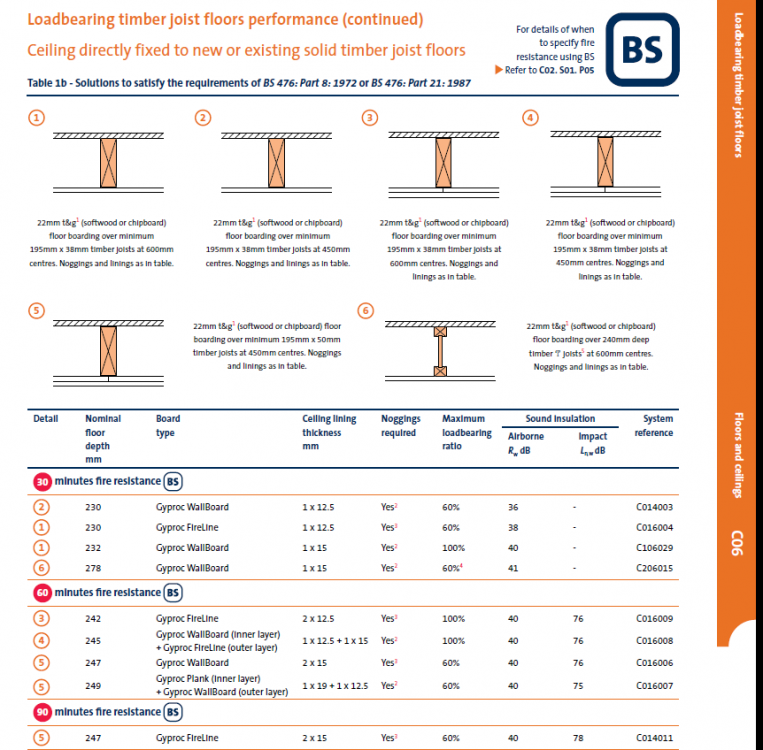
Hello all. Good points from all. Generally if the steel is within a fully protected enclosure then that alone is often ok, no need to protect the individual beams. This is akin to say enclosing a steel beam within a brickwork pier or thinking laterally, a piece of rebar within a concrete slab.. the concrete cover insulates, the rebar stays coolish, thus the floor stays up.. As a general point which I hope will be of help to members. Fire protection of beams etc can be difficult to get your head around, even if you are dealing with it on a fairly regular basis. One starting point is if you can get an understanding of what "Fire Resistance" means. As an aside, the English and Scottish fire regs differ in places but the principles are the same. I'm more familiar with the Scottish regs so to all.. please correct if I misquote the English regs. The overall "fire resistance" of say a plasterboard ceiling / wall or steel beam protection is obtained by combining a number of different properties. One property is called "Insulation" You can see this mentioned in for example the English regs (ER) Approved doc B clause B19. What this property measures is how well the material..be it plaster board or something else insulates what you are trying to protect. Here what you are trying to do is to not just to reduce the "convected heat" but also the "radiated heat" and this is where the "insulation" comes in. We know that say an electric bar fire can set light to your sofa.. by radiating heat.. it's the same principle. You'll also see a property called "integrity" mentioned in clause B19. What you are doing here is making sure that the "insulating" layer is firmly fixed in position such that (in the case of plaster board , fireline board, wall cladding..) the seams don't start opening up. If this happens then sparks, flames and hot gasses bypass the insulating layer and compromise what you are trying to protect. Now knowing this will hopefully help with the next bit. While a single layer of 12.5 plaster board / fire line board etc may give you say 30 minutes (resistance) much depends on what it is fixed to! Say for example you have 50 x 25 mm timbers levelling out the ceiling. In a fire the fixings get pretty hot and the small timbers may not offer the support to maintain the "integrity" On the other hand if you have fixed your plaster board to big solid joists with good "chunky dwangs (noggins) then your ok. Below is a link to the British Gypsom White book. https://www.british-gypsum.com/literature/white-book/floors-and-ceilings There is lot's of good info in the white book for example, often worth just a rough peruse. A good example of the above is to look at page C6 SO6 P04 Here you can see how you can get your 30 min with their product but the info they give only covers you for certain joist sizes and floor thickness etc. I have screen shotted part of the page above. The big solid joists etc contribute to the integrity. the plaster board etc to the "insulation" giving the "fire resistance" Fire protection.. It's a big subject but if you can get your head around some of the underlying principles you can be; safe, get a handle on what you may need for your own particular design and maybe save money too!
-
Cost of Electricity
Gus Potter replied to canalsiderenovation's topic in Air Source Heat Pumps (ASHP)
And running about in bare feet, saves a fortune on slippers which offsets the time you may be extravagent with the heating. -
Interesting thread this. From time to time an SE for example will insert into their terms and conditions of appointment that their liability will for example extend to 10 times the fee value. This is often done where there is say the risk of contaminated land. For example you could design a small portal framed MOT station on an old garage site. The fee for this may only be a few hundred quid but if the ground is contaminated it could have major impact on the structure and clean up costs. The SE could suddenly find they are facing a claim of tens of thousands. It is important particularly when dealing with less experienced clients that the risks are fully explained. This allows them to make an informed judgement. If the client does not want to take this risk then the fee needs be adjusted to reflect this liability. Before progressing it may be worth while finding out what the SE's T & C's were. Pragmatically maybe the best outcome at the end of the day is to contact the SE, explain the current situation as diplomatically as you can, why you feel the way you do and ask them how they may feel about making a contribution to the Church / local community funds as a good will gesture without predudice... and all agree just to leave it at that. While this may appear not to attractive financially in the short term a bit of good will generated now could be very beneficial at some later date.