Gus Potter
-
Posts
2339 -
Joined
-
Last visited
-
Days Won
29
Everything posted by Gus Potter
-
Warm Roof to Cold UNVENTILATED Roof Detail Junction
Gus Potter replied to BartW's topic in Roofing, Tiling & Slating
I think there may a be a good bit missing from this detail. How are the sloping rafters supported, how do you stop moisture passing through the warm roof ceiling and into the sloping part? I think this needs much more thought. I have a similar detail on my own house and it took a lot of thought to get it to work. It's also quite labour intensive to construct. I have ended up with a warm flat roof. The sloping roof is full filled, insulated plasterboard to under side with supplementary vapour barrier. They key for me was to adopt a two pronged approach to the sloping roof. On the sloping roof I used timber sarking with a breathable membrane, counter battens, battens and concrete tiles. The soffit is vented and at the top the roof membrane overhangs the sloping roof with a concealed vent to allow the sloping roof to vent, like a mono pitch roof abutment vent. Basically I decoupled the two types of construction so that the warm roof membrane sheds the water onto a sloping abutment roof. If you look at some of the Marley details they will help, just pretend (it is Easter after all) that the abutment wall is your flat roof. Hope this helps. -
Trusses against brick wall
Gus Potter replied to MortarThePoint's topic in Roofing, Tiling & Slating
A few points worth a look. @MortarThePoint For a short cut you can ask the truss fabricator for the reactions at each end of the truss. Or you can go back and check your calcs. If you want you can show them all but it looks like you may not have included a roof access / snow load / wind load in your provisional calculations. Often once the truss manufacturer knows they are getting the order they wil give you the support reactions. Make sure you know if these are factored or unfactored reactions (with or without safety factors) as this is important when selecting a hanger / choosing the right fixing if using a ledger. Often you find with something like this is all is going great until you try and select a hanger / ledger fixing. Many fixings are rated on being installed in uncracked concrete. Blocks are different and aerated concrete blocks are worse. You find that you can't get the shear / tensile capacity of the fixings to support the loads. Also tie straps are meant to be built into the blockwork as it is going up, their rating is based on this. Face fixing straps requires a good look, not least as they bend, rawl plugs don't have the tie capacity that a built in strap has. In summary, ask what kind of blocks do you have and how can you fix, tie to them. You may find that the truss with the horn removes a lot of issues. If you are in any doubt them please consult and SE. -
Volcane ...500 litres is a fair weight if not going on the ground floor or over a load bearing wall. Worth a quick thought if applicable to your plans. Yes, if on say a first floor you can double up joists and so on but you still often need to get the pipework in. PeterW's point also allows you to spread the loads out a bit.
-
Trusses against brick wall
Gus Potter replied to MortarThePoint's topic in Roofing, Tiling & Slating
Thanks Oz07. This can work out as a simple solution. If you are doing it DIY then it can work well. You can chain drill the pockets with an SDS drill, take your time, avoid dropping a lot of fragments down the cavity (if you have a cavity wall) while getting the pockets pretty level. Also, with a horn like this you get a little more play in the trusses. Say the wall you are joining onto is not straight then you can move the trusses a little horizontally so the rafters of the trusses plane nicely. Often you get the horn a little longer then trim on site to suit. With the hanger option you often find that the nails for the hangers (or hangers themselves) clash with the truss nail plates and intuitively we know that if you have too many nails in a bit of timber this is not a good thing. -
Hello ashthekid. You'll get lots of adivise and pointers here. Look at the simple stuff first. Start at the top.. the roof and check gutters, down pipes and all the obvious stuff. If could well be that by opening up you have let the air into the wall, spring is on us and the wall is warming up, hence the fauna. The pointing looks like it requires some attention so that the wall can dry out properly. Just as an aside it looks like the wall on the outside maybe has had a flush of nutriants. Could be you have a lot of birds on the roof and if the gutters have been blocked you have washed fertiliser down the walls. This is a bit of an odd question but are you near a bonded warehouse, bakery as these can be associated with a black fungus.
-
Trusses against brick wall
Gus Potter replied to MortarThePoint's topic in Roofing, Tiling & Slating
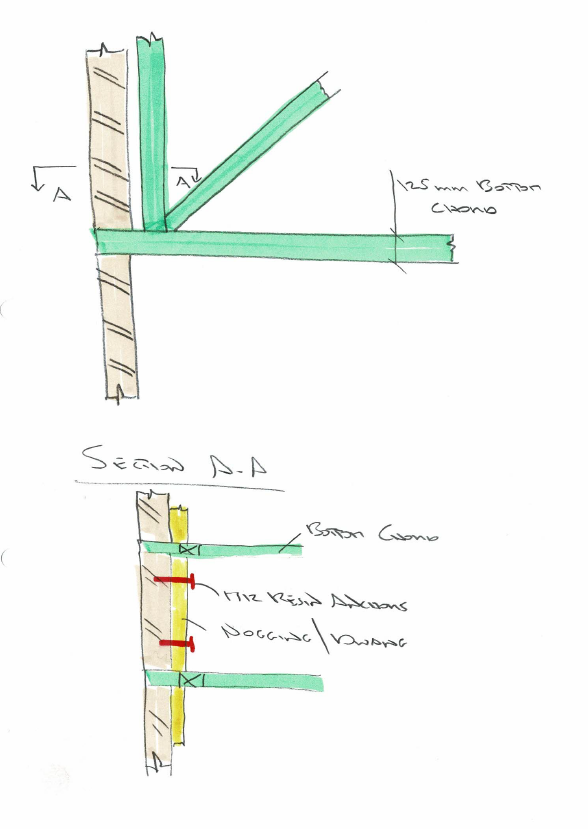
Hi MortarThePoint. The ledger option can work well but as Peter points out you get this twisting effect. Often you get stuck with ledgers as you stuggle to get the fixing capacity. Many fixings are rated on, not least, being fixed away from the mortar bed etc. If you have perforated bricks say the capacity of the fixings really drops off. Expanding type anchors don't work well in perforated brick and there is little test data available. I have attached a very quick sketch showing another way of doing this where you extend the bottom chord and pocket the wall. You can add glued hardwood packers to level up. Here you get a good solid bearing on the masonry and by using the dwangs / noggings you can add extra horizontal tying of the trusses into the existing wall. You may need to beef up the bottom chord a little as it is acting in shear rather than bearing.
-
Hi dpmiller I'm doing a DIY extension in between the day job. Have done a bit of plastering years ago but I have lots of corners and want to get some detail. I want to have a play with some shaddow gaps. Also, I have a nice set of Aluminium windows and doors, don't want them scratched so want to do it myself, although it will take me longer. I have got some 2.0mm stop beads for the window ingoes. I think I'll set them back about 3.0 - 4.0mm from the window frame then mastic to try an avoid that hard to paint / wall paper bit between the window frame and the plaster / ames taping that tends to shrink away over time. I'm not sure how this will all pan out but I want to experiment. Once you get into this type of work then you can't really go on a sq metre price. I'm aiming to start the plastering next week so will try and post some photos etc. and a time / material log on a DIY basis for comparison.
-
Yes, dp's point is worth exploring. Have a look at your floor levels. Also, lift the carpets etc and look at the old floor boards if still there. If it was a coal store, now removed, you may be able to see how the floor has been patched up where the old coal cellar walls have been removed, all these clues a can help.
-
Temporary Stairs - Cut and Join two Halfs
Gus Potter replied to NewToAllOfThis's topic in General Construction Issues
Well done Conor. Yes get the hand rail on and don't over load them. Let us know how "bouncy" they are once you have used them for a bit. Once you get the hang of it you can do some cracking stairs going the over cladding route. -
If you are self building and have a temp cabin / static caravan then yes you don't want it to blow over in the wind if you are in a windy spot. Depends on how long you need the cabin for. Say a year to two.. two winters. Here you can build some planters, fill them with soil and take ratchet straps over the roof. Pad the straps so you don't damage the roof thus can sell temp home on to another self builder with little if any loss if you look after it. You can build the planters on a pallet with a spreader board under, round which you put the strap. The strap does not rot as often they are nylon, and, as it is Easter at the moment you can decorate said strap with bunting or whatever takes your fancy. The great thing here is that you can start to play with your plants, get them started, grow raddishes, herbs etc for fun, it can take the sting out of some builder problems, small daft things like this can motivate you to carry on. Some times when all is looking glum then you feel that you are making a start on the garden and eating you own food! Great for kids too! As a rough guide if you live in a windy spot then you could get some 100 -150 kg of uplift per square metre of cabin roof area. Thus if you take a 3.0m wide cabin then you'll get about 0.5 x 3.0m x 150kg = 225 kg max per side per metre run. A planter ( 1.0 x 1.0 x 0.5 deep) weighs about 600 - 800 kg so if you site them at about 2.5 - 3.0m then you are on the ball park to holding everything down. You can calculate the uplift wind forces on a temporary structure but there is a fair bit in it if you don't want an overly conservative design. Oh, and back to the fun bit. It can lift the spirits to have planters etc and play about when you are stressed / knackered. With a leep of faith you can "almost" think.. like this is a camping / cheep holiday home in reverse. Enjoy the "glamping" as this can be part of the selfbuild experience that you will always remember. Lastly in terms of the cabin settlng this is often less of an issue. A bit of hard core, a few slabs, monitor from time to time and jack / pack the legs if need be. Basically if the doors and windows start to jamb or you can see it running off on a spirit level then and re level. It's the wind uplift that is the dangerous bit! All the best.
-
I'll touch on the soft skills. Most of us are not daft, yes we have our daft moments from time to time, posting on BH is probably one of mine. A while ago there was a sales theory called the FUD factor. You can read about this on the web (for some on BH.. to take you back..Motorolla / Six Sigma etc..) but it goes; fear, uncertainty and doubt. You puntloos may be at the uncertainty stage? I would start to talk to builders, they will be keen as you now have your permissions. They will take your job as a live job that is worth them putting a bit of effort into getting. Don't forget that this is a people business, builders are people too. Some are great, the best will guide you, deliver what you want, look after you..you can become long term friends! Trust your gut feeling. Open up and start talking to builders, tell them what your are worried about..discuss the technical aspects with them. The builders you want will answer a lot of these questions. You will need to put a bit of work into finding them as they will be very busy. These builders are not cheep but you get what you pay for.with. A good team can work together to get the job done.. you.. the builder and designer! Have a look at this people side of things and it can take a lot of worry out a job.
-
PCC requirements from architect
Gus Potter replied to RichyC's topic in New House & Structural Warranties
Much depends on what you are after. Do you just want some paperwork to get you over the line for lending. Or do you want someone (Architect say) that will keep a real eye on the build quality (rather than the absolute basic race to the bottom, minimal visits etc, all caveated), help you out a bit if you have an arguement over the builders bill or nip to site if the builder gets stuck and needs some reassurance? Yes, builders are human too, sometimes they just need a hand / maybe talk about something they have not done before with the designer. Remember that builders need to learn / gain experience as they progress in life, just like the rest of us. You can for example discuss with your Architect what it may cost to keep a "watching brief" over the job. This is a half way house between full contract administration and site supervision (with the associated cost) and you just being left to get on with it on your own. This can work but needs to be set up the right way. Essentially for you if all goes ok on site you can save a bit, if not then you have backup. However, to make this work requires a bespoke agreement. It can pay dividends but you need to do a bit of work and be able to take a holistic view. I would look at this in the round. Set this up right and you will save much more than the differance between the warranty and PCC cost. Also, set it up right and you probably won't need to make a claim, thus the level of PI cover is much muted and you can enjoy your house without getting into a barny. If you have a complex house in terms of engineering then also look at what cover the SE has. An SE may carry some £1.0 - 2.0m PI cover even for domestic work. -
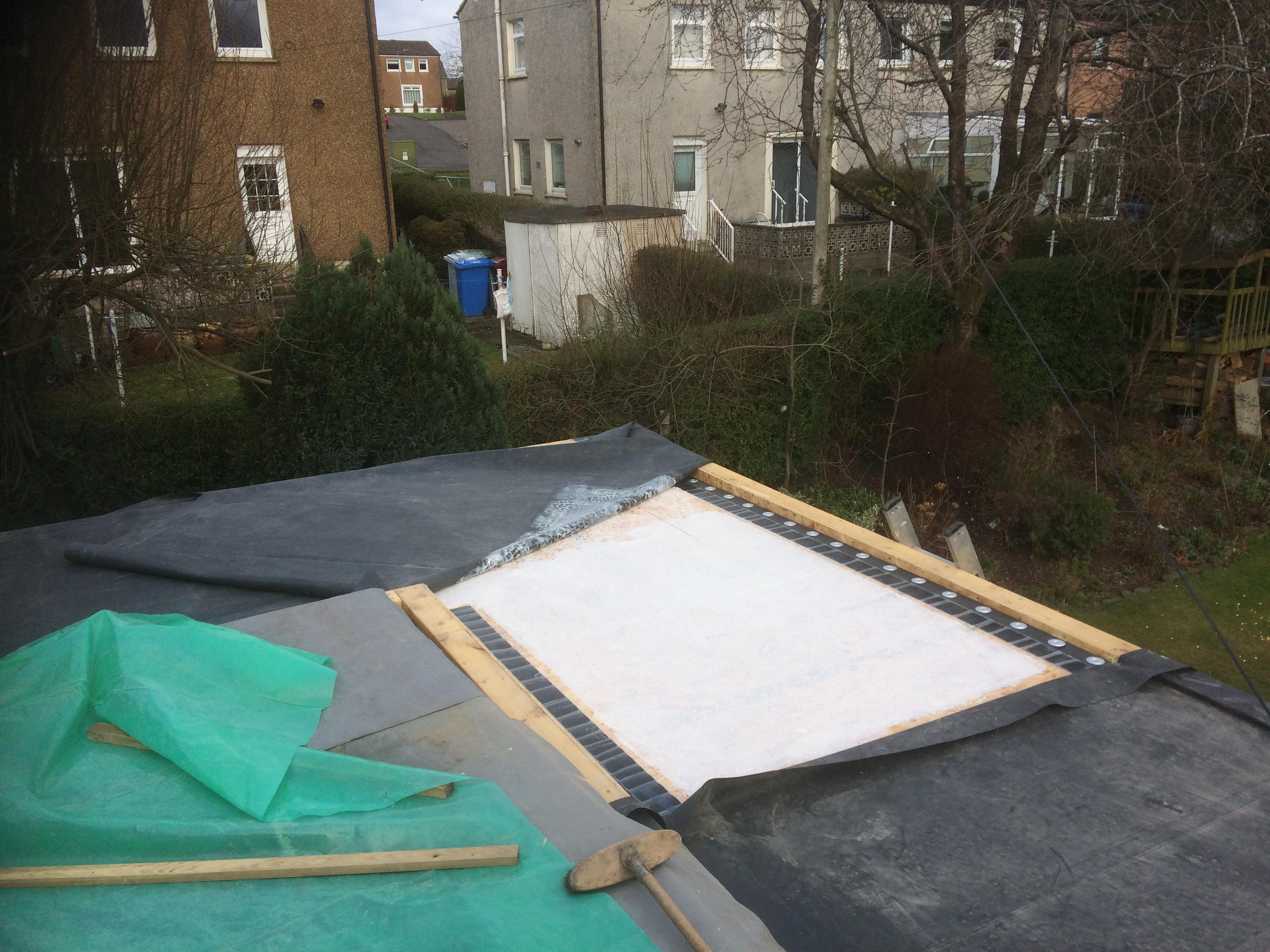
Hi JTB. Yes I did basically glue it all together. I have little worry that the right glue will last as Steamy Tea and Joe mention. The main thing for me is that it best suited me as I was doing it single handed and DIY. I avoided these long fixings, repeating thermal bridging and so on. Also, I have at the back of my mind how the insulation may creap. Most insulation, is speced with regard to it's compression stiffness but creep is not often explained. For the creep behaviour think about a timber beam, it bends under the initial load but over time it creeps too, how much does PIR creep? If you take all the load off maybe it won't return to it's intitial shape. I wanted to avoid any issue of the insulation creeping over time. Once you get to these insulation thickness' (200mm PIR) I was keen to make sure that the insulation is not going to creep (call it shrinkage ) and pop the fixings up through my rubber roof in the long term. I have a low parapet and found this quite simple to detail and do. The membrane continues up and over the parapet. Basically my roof is like a thick pond liner with a few edges that allow the water to run off. There is no noise as there are no areas of fixing stress concentration say.. thus no creaks.. so far. The main thing for a long lasting roof is the quality of the workmanship and attention to detail.
-
Temporary Stairs - Cut and Join two Halfs
Gus Potter replied to NewToAllOfThis's topic in General Construction Issues
Yes is does look that way but the stringer is probably getting on some 250 + mm deep. The treads really stop the stringers from twisting and thus reduces deflection. Also, as the stairs are at an angle unlike just say a floor joist some of the load component on the tread acts as an axial load down the stringer so it is not subject to as much bending force. Timber is quite good at resisting axial loads. Think about a ladder up against a wall, when it is really steep it does not bend much as your weight goes down the length of the ladder. Put same ladder flat and walk over it it will bend a good bit. A stair is a "halfway" house. Yes James, once that timber has sat for a while, dried out and stabalised to the prevelant moisture content you could think about over clading / veneer. -
Temporary Stairs - Cut and Join two Halfs
Gus Potter replied to NewToAllOfThis's topic in General Construction Issues
What is your floor to floor height and available pitch? Are these intended to be replaced by say an oak stair later or will you fill in the temp stairwell later on? If you are fitting them in the final stair opening then as a self builder you could go the American / Canadian way where they fit the stair carcase for the builders to tramp up and down. It seasons during this time. Then when all the builders have gone you get essentially the Cabinet maker / French polisher" in to over clad / do the hand rail with the high end (veneer) stuff right at the end when all the dust has gone. Practically it means that if you run out of cash for a bit you can still get the house finished and you just pay for the stair carcase and a basic hand rail boarded below. There is a wee bit of a rub in that if you get a difficult BC officer they may argue that all the rises are not the same. You can put a bit of feathered ply down top and bottom to create a temporary landing so everyone is happy? Also, if you get a dog / Zebra and let it have the run of the upstairs you can review after a few months how much you want really want to spend on a solid high quality timber stair. -
It's late here for me but I have to say and please excuse the spelling / grammer. Hold the bus here, if you do this, although very tempting, you are on a very rocky road. I would advise not to do this. Take this action and you will in my view come off much worse and expose yourself to a big legal bill and, worse.. You have other options. These are : Go back to basics, get some local authority weight on your side, with their financial clout. Here are a few points to give you a flavour on how you can get this under control, and maybe benefit as an unintended consequence. I can expand later if you wish. Write to the council and say that you have a concern that they have built a habitable structure on an unproven foundation. Explain that they have not had access to your land to determine the size of the existing foundations and thus if they have not done that then how do they know the (foundations) are safe. Also ask about this being a fire boundary wall. These conditions apply. It may be that this "Architect" has not complied with the fire regs. Ask this question. I have a big check list but suffice to say once you start to ask legitimate questions then these can sway matters. Next. I would have a guess that they have opened up more of the existing main terrace rear wall to create a more open plan space. If so who is the SE that has signed this off. To explain. If all the home owners in a terrace cut a big hole in the rear wall then the whole terrace of houses could be unstable.. thus this is a public safety matter and that falls within the remit and expense of the council to pursue. Once you get this ball rolling then this "Architect" maybe can't sell on, maybe even can't rent it out as there is a fire safety / structural stability issue? To defend this the "Architect" needs to now defend against a well funded public body. For me I would rip it to death on the structures, safety side and a bit of technical stuff, get the council on board and turn it around, your expense will be your time alone. If this does not work.. it usually does, then by all means consider the drastic legal option. One key is that as soon as you get the local authority behind you on the safety issues ( which what we all should be doing as we don't want to live in houses that will fall down) then you are on the way to sorting it out. It may even be that once you get this chancer on the back foot then there may be some compensation coming your way / agreement for you to build too should you wish? The easiest and cheepest way is to hammer them on the engineering / safety side , it's often a winner as this is where they (chancers) are weak!
-
Yes there is. When you come to dealing with "house" builders there are some simple steps you can consider that may help concentrate their minds. It is not uncommon for house builders to "regrade the ground" and they maybe just (from time to time) interperate the SE's or planning conditions in a different way. Often when they do this they move muck from one part of the site from another as the cost of disposal off site is high.. just say. But when this happens that muck used for "regrading" may also have the odd "juice can" or a bit of tape from a pallat of blocks / bricks in it. If you are inclined then you could dig a couple of holes and see what you find. This simple step may be enough to break the impass. If you find something like this then put a measuring tape in the hole, photograph it, describe what you have found and ask them to explain how something "modern" may be found at this depth. The key here is to take your time and one stage at a time. Some developers I my view wage a war of attrition so be prepared for the long game and slowly gather evidence.
-
Thank you @ianfish and conor for the compliment, it's really appreciated. I have made a few practical mistakes.. maybe some technical ones too! For example. I laid out the membrane for a while after it came in a back off the lorry (it was much heavier than I thought being on my own) to let the creases settle out. It thought I had got them all but I failed so a bit of the roof still has a crease in it. It's still water tight and I may come back to it at some point. But at the moment I need to finish the rest of the job! Every day is a school day! Thanks again for the compliment.
-
Hello David. Hope this is of some help and gives you a bit of an insight as to what you have. I can't expand the drawing enough to show the detail so the following is an overview. I have written a bit but also attached a very quick sketch. A starting point would be to first look at the steel beam that is I assume forming the top of the portal. You have the floor joists framing in on one side, a bit of masonry, what looks like the timber frame and maybe a bit of sloping roof framing in, but this framing is intended for restraint rather than load bearing. Each of these elements will impose different loads on the beam at different times. For example you could have a party (with lots of refreshment) and no snow or wind.. thus the floor joists will load the beam more at that time. You may also get a uniform snow load on a night where there is no wind. You may also get a windy night and here again this will cause the beam to be loaded differently. Call these different load cases. You can see that all the different bits of the structure don't rest over the middle of the beam.. they are offset from the centre of gravity. When you offset a load on a beam it can cause the beam to twist.. torsion. Now when you design a beam like this you need to consider all the different load cases.. and you can easily see how you can get a few combinations. Designing these portal type frames can be a bit of work when you get torsional effects. A lot of SE's won't be that keen to do it (include for torsion) unless you pay a bit extra or are a client that appreciates this finer point. You have options but two of these are to either design the beam for torsion, and the associated portal connections or to use the joists that are framing in to resist the torsion. In other words for the latter you transfer the twisting effect back into the floor joists. If you do the latter you can often reduce the sizes of the steels and the connection sizes. But there is no free lunch! The forces need go somewhere. You also need to make sure that all the bits framing into the beam are tied together. This tying is very important as when say the wind blows it wants to pull the building apart at times. That may be partly why you have the straps. I can see the straps on the drawing, but they seem to be side fixed to the floor joists, practically this can lead to splitting of the timber, especially if the joiner etc does not get them right first time and is not familiar with the minimum timber edge distance for a nail. We know if you put a nail too close to the edge of a timber then the timber can split, splinter etc. Also, the straps seem to have an extra crank in them as they need to bend again back down to the top flange of the steel. Best to confirm what manufacturer the SE ( I can't see enough of the drawing) is proposing for the straps and whether this type of strap cranking is ok. Also as the timber shrinks in the vertical dorection will the strap not start to force the joist away from the beam? If so by how much? One option I would look at is to get the fabricator to weld fin plates on to web of the left hand side of the beam. This would allow you to bolt through the fin plate to tie the floor joists to the beam. You could also then explore whether you can reduce the size of the beam by extending the fin plates a bit. You would need to check the floor joists again though as they would be loaded differently. You are now using them to take the torsion out of the beam. On the right hand side you could get the the fabricator to provide drill holes in the web of the beam at 1200mm centres. Budget roughly that a drill hole is about a £1.00 a go for standard domestic type beams by the fabricator. You would then insert threaded rod through the web and extending mid depth within the roof joists. You dwang adjacent to the tie rods. Now you have simplified to some extent the buildability issues, removed a safety risk in terms of playing about with what can be an unfriendly tool (shot firing) in the wrong hands. Generally, what you do is to get the fabricator to do all the hard measuring by way of controlled drawings and remove as much complex work as you can for the folk on site. Yes it may on first glance appear that we are adding the extra cost of the fin plates but the labour savings could well pay dividends. Make it simple stupid! Also, you can get a better job as you are controlling these difficult details in a comfy office, rather than the poor builder who often has to do this with the rain running down the back of their necks and up their shirt sleaves. One good thing about the tie rod / fin plate appraoch is that it lets you form up the roof ventilation more easily as you have moved all the steel connection design out of your ventilation zone. Have attached a very quick sketch to assist. I hope I have given you enough info to enable you to ask your Architect and SE if this may be some kind of option worth developing up. Remember that you can ask ten different SE's the same question and get ten different answers as there are many ways of skinning a cat. One key is to explain what suits your method of approach, how you want to finance, programme the works. You can hopefully now say that you have read that there may be other ways of doing this.. often once an SE sees that you have put in a bit of extra work so will they, sometimes for free too! Beam sketch 24-03-21.pdf
-
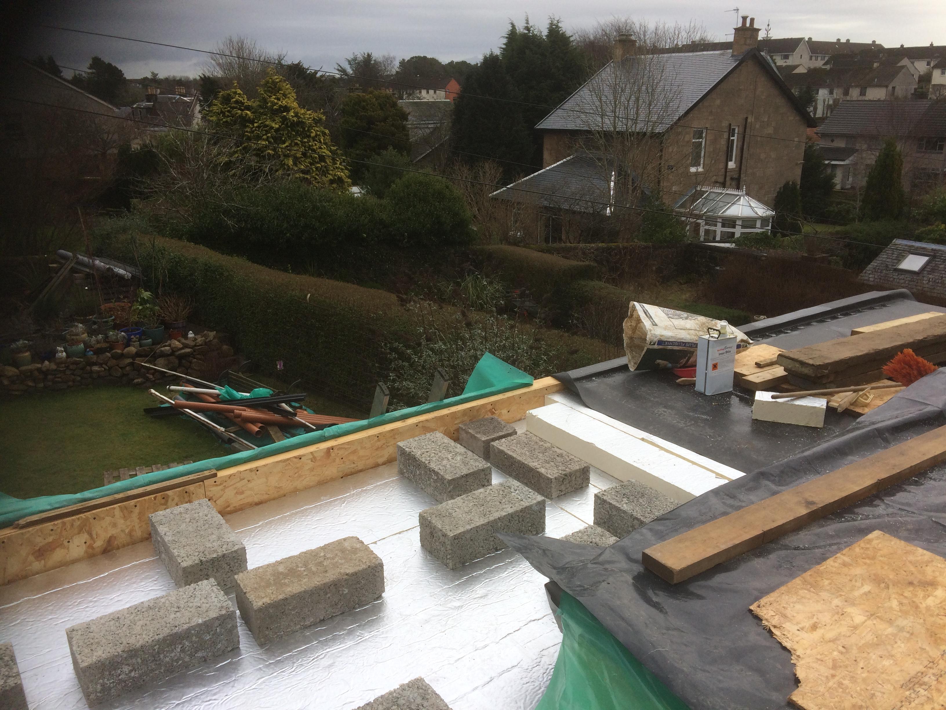
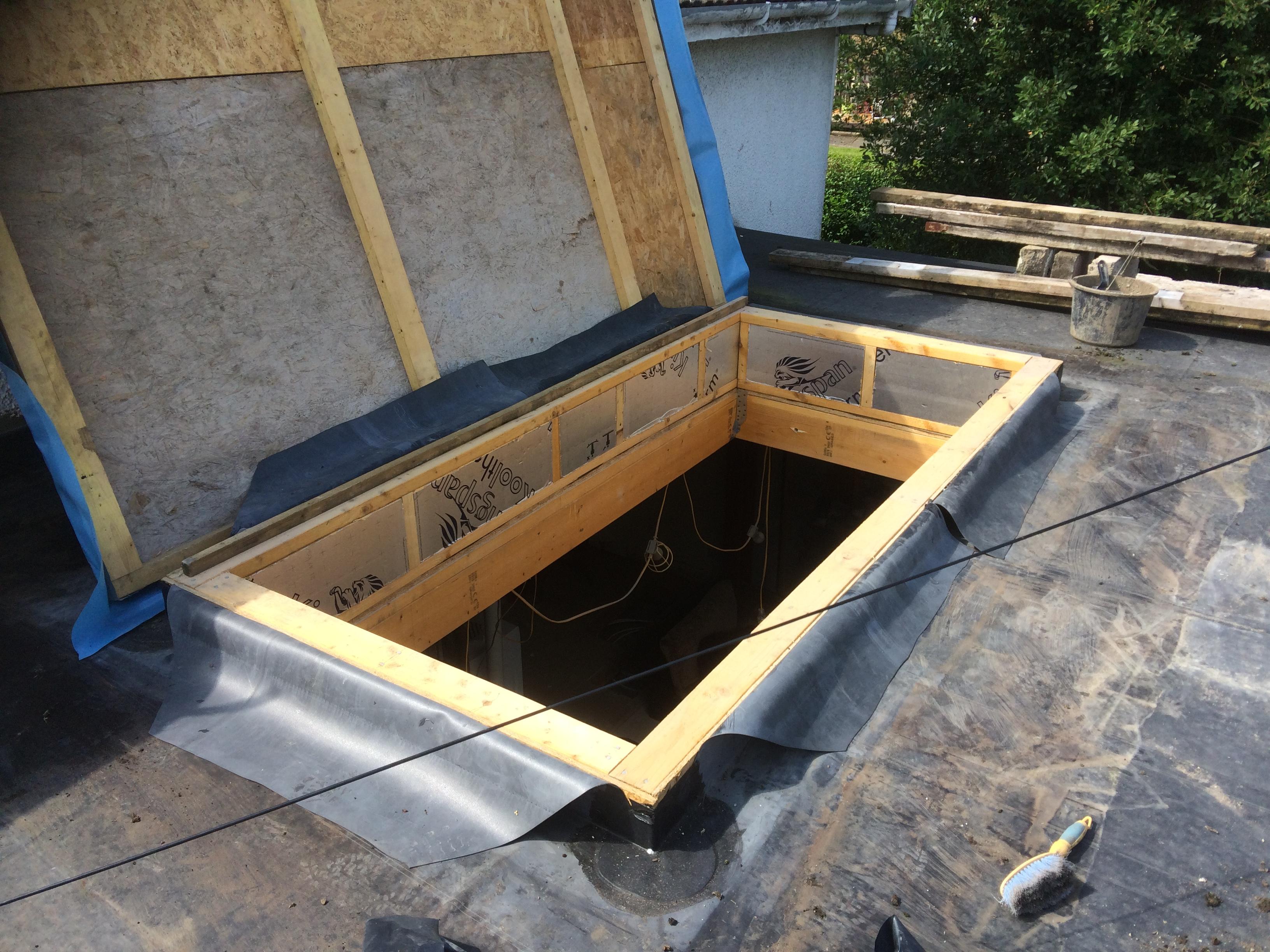
Hello JTB. Yes I had the same issue. My flat roof make up is: EPDM rubber glued to 18mm thk OSB3 glued onto the top of two staggered layers of 100mm PIR (thus 200mm thick) on vapour membrane. Vapour membrane is on 18mm thick OSB3 resting on 195 x 45mm joists with 12.5mm plasterboard on inside. I plumped for this as I was doing it single handed. The glue for the insulation / OSB3 interface is a poly urathane (PU adhesive), I used Insu stix, the can is in the photos. Very effective. I did the membrane in two halves as it was too heavy and bulky to handle on my own. The blocks are to weight down the insulation while the glue cures. And yes the pipes in the garden etc can do with a tidy up. Roof lantern in progress. I also opted for this solution as the weather is a bit unpredictable here. As there are no fixings then no potential thermal bridges, problems installing a fixing through 200mm plus insulation and hitting a joist etc. Hope this helps flesh out your ideas. Only issue is you have a pretty thick roof so I'll maybe use some careful shaddow gaps etc to try and reduce the tunnel effect at the lantern. It looks promising at this point.. nearly ready to start messing with the plastering here.


-
Russell. You beat me to it by seconds.
-
Hello Charteris. That's one of the reasons I joined BH too as folk are helpful, you can make a daft post and not get pelted for it. It's also a great place to learn stuff. Could you do a wrap around single storey extension, you may have thought about this already. Keep the walls 1.0m off the boundary say. With a wrap around single storey you can vault the ceilings etc, bring light in from the roof.. loads of options. Then you get to play with a layout and kitchen design. It may be that you are looking for something of higher quality rather than just a lot of extra floor space? But, if you do this wrap around you can cut off car access to the rear if you want to put a garage up in the back garden. It can be trade off. Do you just need extra bedrooms or do you want to create a great living space all on ground level? Sometimes getting knocked back to start with can actually be of benefit as it really makes you think about what you need and want. This can allow you to spend more efficiently. All the best with the project.
-
Just a thought but if you got a drainage contractor in with a mole (makes a hole say for a cable / duct) under a road then you could maybe make an argument this way? Avoids trenching the ground and cutting all the roots. In principle this may work. To start with aim to keep the mole deep in maybe low nutriant soil so you reduce the risk of damaging the primary roots. In practice.. I'll leave that up to your imagination. If you don't want to imagine then get in a pro Arboriculturist who may be able to look at the soil, refine the general guidance on the extent of a root protection zone and keep you on the right side of the regs. If you hit an obstruction using the mole then you can hand dig to clear it and.. while hand digging you make sure you don't cut the roots.
-
Hi Craig and Iceverge and all. Thanks for posting, great stuff for me to see how folk innovate, approach design. Can I ask what sofware are you using to model the window reveals? Is it a small package (spread sheet) for just heat flow or are you using part of a big expensive Finite Element package like Abacus?
-
Iceverge, I hope I have not put you off but I think that you could better spend money on making sure you get a good quality of build. By all means use your calculations as a target but the key will be the quality of the workmanship and attention to detail. For example if you put up a timber kit that is soaking wet, then fill between the studs with PIR insulation. Leave it a few months and you'll find gaps between the studs and the insutaltion as the timber has shrunk. You'll also find that the PIR you thought was fitted tightly is moving about a bit. It now acts as a duvet with your leg out the side of the bed! If you can get a handle on this type of behavoir and seal things up, look after the quality of the build and material then you can get a cracking job without resorting to more expensive materials.