Gus Potter
-
Posts
2339 -
Joined
-
Last visited
-
Days Won
29
Everything posted by Gus Potter
-
Ah.. dangti6.. can of worms here in terms of floor slab tolerances, quality and variations in level. I have attached a copy of a report that was published on the web that is very informative. It deals with floor level tolerances and flatness. A floor can be flat but not level! Many domestic contractors say a slab will be smooth.. but..! For all.. it's well worth a read if you are into ICF, basements, floor slabs etc. Page 5 onwards could save you a lot of grief. Credit is due in full to Combined Flooring Services Ltd and the author Martin Rogers. I have found this report to be a very handy reference document. Thank you Martin if you are reading this. If your slab is a structural slab then it is important to control the thickness and variation in thickness. This is where control over the level top / bottom and finish is important. Floor_level_flatness-survey.pdf
-
Hi cwr. Run this by your SE. The thing is that the SE may be relying on the frictional / bond resistance between the floor slab and the wall to provide lateral stability to the building. If you introduce a slippy bit of plastic between the slab and the wall as tonyshouse says you could be making a rod for your back. Foaming up the ends of the slab looks a bit simpler as suggested.
-
How to deal with difficult builder?
Gus Potter replied to Adsibob's topic in Project & Site Management
For all: A thing that is worth while putting on your drawings for conversions / refurb if you are an SE is an approximate steel size. State this is to be confirmed by the contractor on site along with a note that explains the allowable tolerance. For example it's good to see a note such as.. "this steel beam has been designed to accommodate an increase in length of up to +/- 50mm. Should the site measured length increase beyond this then the SE should be consulted prior to fabrication" or words to that effect. I'm a bit surprised that on a refurb / conversion the founds were not fully explored at the very early stage of the design. This is fundamental to any conversion / refirb etc. You must understand what it is sitting on and what you propose will impact on the sub structure. Strolling now through the design process. On a barn conversion, extensive refurb say your Achitect should have discussed with you the benefits of getting and SE in early, the design/cost risk if you don't. If you are resistant to this (unless with very good reason) then they should walk away from you as a Client.. An SE should also walk you through the structures side and explain how and what they need to do to realise the Architectural design and how they are going to collaborate with the Architectural designer while keeping an eye on the structure cost which you often don't see. Again if you are resistant to this then you should be left to your own devices. As a Client why buy a dog and bark yourself? Sort this out and it gives the contactor a clear view of what they need to do, how they will make a fair and justified profit, what help and support they will get from the design team when problems occur and what the concequences will be if they don't hold up their end of the bargin. Have a fair contract and you are well on your way. On a refurb / conversion this can fundamentally impact on the design process / cost. Not just in terms of the structural design but on how you deal with the design / interface of the insultation envelope and the associated labour / material cost. Often understanding the existing founds, level changes, the existing wall construction, moisture control leads you to the simple stupid option which is effective and most cost effective. From time to time you can, if you get your SE in early and are prepared to open stuff up (intrusive investigation) then you can get your steel work and fabrication drawings pretty much spot on. You need to spend the money up front with the SE, opening up / exposing founds, but it reduces your risk later on. Also, the more information you gather early can allow for a more collaborative approach which tends to be more enjoyable for all involved in the project. Lastly, if folk are enjoying the job they may be a little less heavy handed wth the invoice pencil and spend more time getting the job done. -
new floor with bolted joist runners and joist hangers
Gus Potter replied to cs21's topic in General Structural Issues
Hi cs21. Thanks for responding. This is a bit of a quandary. There are lot's of folk that have building experience that have a feel for what will stand up..it's just that often folk don't consider that we mainly design for a 50 year life span (domestic loadings for dwellings.. flats are a little different) and the loads that have a significant probability of occuring over that time. That is why we have safety factors. We very rarely see a house failing drastically due to over loading alone (I can't think of a case off the top of my head.. there have been some localised floor collapses due to folk hoarding stuff I think).. it's usually due to bad workmanship, changing the specification of materials without consulting the designer/ making what appears to be a small change in say levels of ceiling joists, inadvertantly altering the way the roof trusses work.. suddenly what seems to be a minor change can impact on the loads paths and result in an unstable building. I may have interpreted this wrongly but is the roof already vaulted? If so do you understand how the horizontal thrust from the vaulting roof is resisted. If you are proposing to remove the existing ceiling ties to form the new floor (bottom truss chords say or an existing floor that is set 2 feet down from the wall head that is providing some tying / lateral stability to the existing masonry walls for example) do you fully understand their function and the consequence of removal. Also, have you considered the practical issues relating to how you install the anchors, how they will fit with the coursing both vertical and horizontal so that you maintain the edge distances between the fixings and the mortar joints. Will your runner sit flush with the wall or will it stand off a bit in places if the wall is not straight. If standing off in places then you introduce a bending force into the fixing and this has to be considered. The capacity of some of these fixings can drop off four fold and more depending on the type and condition of masonry you are fixing into. Have a look at the manfacturer's load data and you'll see there is a bit of thinking to do to get this to work. Look carefully at the data as many fixings are only certified for cracked concrete.. not masonry.. even then much is based on EU brick / block sizes not UK sizes. It may be that you just want to cart on based on what you think is fine. But if you pass this house on to relatives or sell to say a young family then you would surely want to know that if they use the house in a different way it will still be safe? Also, say you come to sell and you are asked to demonstrate that what you have done is compliant with the regs in terms of the structure. Will you be able to do this? -
Hi Peter. To get the best out of BH then consider posting your drawings. This way you'll get better / focused feed back, maybe a few tips that could save you money.
-
new floor with bolted joist runners and joist hangers
Gus Potter replied to cs21's topic in General Structural Issues
Hi cs21. Can I suggest that you reflect on the fact that there is a difference between being confident and competant to design and execute the works in a safe structural manner while also keeping an eye on the cost, both short term (the works) and long term.. if you come to sell. George is giving you a heads up that could save you a lot of grief. Yes, you may have managed to size your joists (ten minutes work to get a concept joist size for an SE / competant experienced builder) but there is much more to this than just sizing joists. You are asking about the fixing types, hangers.. no mention as to how your proposals may affect the global building stability. If you are competant then no need to ask the questions you are. I would spend a bit more time mulling this over, a bit more research perhaps? BH is a great place to find the info you need. -
Wall ties for 200mm cavity retaining wall
Gus Potter replied to Moonshine's topic in General Structural Issues
Hi Moonshine. What you have looks like a reinforced masonry retaining wall. I assume you are using dense concrete blocks not aerated. Nice to see them being used, a bit like timber flitch beams which seemed to go out of fashion for a bit, like bell bottom / flared trousers. Yes 325mm ties to allow for construction tolerance so you get your min 50mm embedment. Peter has suggested (I think) using A142 on the flat to create the wall ties. I would maybe give this a swerve as the blockwork is more porous to moisture and air than well compacted concrete. I think this risks corrosion of the A142 in the blockwork courses. The issue here would be that when steel corrodes it expands and can exert a huge expansive force on the masonry which could damage it. This effect can be seen on historic buildings where iron straps, cramps etc have been built into the stonework resulting in disappointment. I'm curious as the cavity fill is quite thick.. I wonder if the wall is fairly high for a reinforced masonry wall or if you have a clay soil that has a low shear strength. By that I mean a clay soil say that is pretty soft thus exerts a fair bit of lateral pressure on the wall. I can see that the ground slopes up from the wall so this tends to add lateral load to the wall too. I would be interested to see the detail of the rebar at the base of the wall and how the base is working. For the curious these types of reinforced walls are quite clever in how they work, it's the simplicity that attracts. To explain a bit of the theory. Imagine you have a reinforced concrete beam spanning between two walls subject to a downwards load. The bottom of the beam is in tension. Concrete is not so good in resisting tension so you add in rebar in the bottom which is good for the tension. The top of the beam is in compression and concrete / masonry is good at resisting compression. Now, if you make the beam deeper the tension and compression forces at the top and bottom edges reduce as you have a longer lever arm between the bottom and top of the beam. A bit like using a longer spanner or car wheel nut brace. Imagine you take said beam and cut an imaginary slice through it just off the middle of the span. In the very top you have a compressive force acting in one direction, a tension force acting in the opposite direction at the bottom of the beam. In the middle of the depth of the beam these opposing forces are at their maximum in the direction of the span. For the very keen these longitudinal forces are often called complimentary shear forces. In summary, they are most onerous in the middle of the beam and reduce to zero as you move towards the top and bottom of the beam. Now a reinforced masonry retaining wall wall works by recognising that these complimentary shear forces reduce as you move towards the inner face of the wall. There comes a point where the concrete has enough bond strength to the block to resist the complimentary shear. You hit a sweet spot where you can get the concrete and the block to work compositely, like a metal deck floor. The wriggly tin resists the tension, it is bonded to the concrete which resists the compression. Again, great to see this kind of reinforced masonry detail. They can be a great addition to your design armoury. For the self builder they can deliver savings, particularly if you have lot's of masonry on the job anyway. Like many retaining walls they are often height /soil sensetive but they can be great given the right conditions and save you money. Moonshine..One key thing is that you need to make sure that you keep the inside of the blocks clean, no chucking the washout from the mixer down the cavity, letting soil fall into it. Also make sure the brickie does not butter up the inside of the cavity as you want the inner face of the blocks as rough and clean as you can to make all work. Keep the blocks moist when pouring the concrete as you don't want them to suck the water out the concrete on a hot summers day which will encourage the concrete to debond from the blocks. -
Block and beam floor buildup for insulation?
Gus Potter replied to puntloos's topic in Sound Insulation
Hi Puntloos. Copied some extract from your last post in italic and added my thoughts. "My own design, but in particular note that the external wall is much thicker: 435mm: skim 5mm sandcement plaster 15mm medium block 100mm EPS blown beads (with stainless steel wall ties perhaps) 200mm medium block 100mm sand cement render 15mm But perhaps more importantly, split the large glass pane into two much more modest windows. Would your suggestion of the 'portal frames' still hold? My pier design and location is somewhat more central to the main area. The piers don't contribute as much as you would like to the horizontal stability, unless you have plenty load coming down from above to assist in resisting the overturning moment from the wind. With a 435 thick external wall it kind of rules out some kind of portal frame with a bottom shelf angle to support the external leaf as you probably generate too onerous a torsional moment (twisting effect.. does not interface well with glazing) which will cause problems, not least with the portal connections given the space you may have to form said connections. It may work well with a portal for the inner leaf (deals with the horizontal stability) which will carry the first floor and roof loads and some off the shelf lintels to support the outer leaf. If you can decouple the inner and outer steel it makes it a bit easier to deal with the thermal bridging. -
@canalsiderenovation Hey on the upside you're in now. Suggest two diagnostic approaches. 1/ Ask everyone .. again, if they have "done something they should not have done" in the shower.." Explain that you have been on BH and unless they come clean you will find out and make it public... if that fails..(and it probably will as I bet you have already explored this) then option 2. 2/ Buy a plunger, one of the ones that act like a bike pump may be the thing. Get a big drum of warm water (not boiling as you may crack the tray) pour it into the tray to get a head of water say 50m m in the tray. Plunge like your life depends on it. Report results here.

-
Have a look at how crib walls are constructed. Plenty info on the net. Don't push your luck and try and retain a big embankment, but for a modest garden retaiing wall well away from the house it may be the thing for you. Also you could look at gabion baskets. With the right choice of stone they can look great and provide the right habitat for wild flowers etc.
-
@the_r_sole My thoughts on this "There's a bit of confusion here, the architect would act as a contract administrator whilst the work is on site - not a project manager " Good point as there is a big difference between the two. For all you can find stuff on the net about this but simplistically an administrator handles the paper work.. on a small domestic project it is usually the builder that organises the day to day sequencing of trades, running of the job and standard of workmanship. "(a QS might also do this role which is why they'll be advising to ditch the architect)" Food for thought. Any construction professional that makes such recommendations should only take this course of action when it can be backed up by evidence of failure to perform. Unless of course they wish to commit professional suicide or attract a legal response. "If you're at the stage of nearly building and you haven't got enough trust in your architect that they're not acting in your best interest then don't go any further - contrary to popular belief I've never worked with any architect who would deliberately inflate costs to get more fees, they also should have zero financial incentive to steer you to their "preferred" contractors - that would be contrary to the code of conduct (and pointless)" Agree with the Sole. In any profession you get the odd bad apple but consider that Architect's, SE's, QS's often spend between 4 -5 years at uni, another 3 - 5 years training post graduation and another 3 -5 years becoming modestly competant. Even then they still have to continually train and complete CPD. Basically it can take you 12 - 15 years to get to a level where you can practice competantly. There is absolutely no incentive to bend the rules for some short term financial gain. "As mentioned, building control drawings are not construction drawings and won't have enough information to build from, so you're much more at the mercy of a contractor making assumptions if that's what you use as a basis for a contract, also if you're borrowing money to do the work you may find that a mortgage provider requires details of the contract being used and details of the contract administrator... " Well articulated by the sole. "But as I said earlier, if you've got this far any you don't trust the architect there's something very wrong in the relationship so probably not worth continuing with them - if one of my clients told me they were worried I would inflate costs for my own gain on their project that would be a red flag which would end my involvement. " Yes agree with the sole..but I would always explore why they think this way. Often it's just nerves that get the better of folk and they say daft things. A good professional who is used to dealing with domestic clients will appreciate that you may be nervous and seek to resolve this trust issue. If any advisor / designer fails to address your concerns then part company with them before you start spending big sums of money.
-
Strip footing and eps slab for timber frame?
Gus Potter replied to DragsterDriver's topic in Foundations
Hi Dragster Driver. @DragsterDriver "waiting on planning permission and then turnaround time on a slab design and delivery could be financially crippling- I really do need to ‘hit the ground running’. I have easy access to plant and groundworkers/bricklayers who owe me favours" Is there more to this? just had a scan at your drawing. Seems like you have a simple raft but a suspended floor over. What do you know about the ground? It may be that your SE does not know that you have these construction contacts and this may have swayed them towards the raft as the most economic based on the info available to them. It could be that if you can call in favours that suit, you can excavate deep strips, get the muck away cheep, do a trench fill strip found all over and cart on? -
Block and beam floor buildup for insulation?
Gus Potter replied to puntloos's topic in Sound Insulation
Hi Puntloos. That living room is a chunk of space. Here are my thoughts on the layout you have provided. Much of this is SE related but I hope it gives you some pointers. You have a pretty clear main rear elevation. If you look at the right side of the drawing you have a small return on the masonry, then a pier between W-05 and D-03, the access to the dining area and a long wall up the left side of the drawing. SE wise this flags up how to stop the building moving from side to side in the plane of the rear elevation. Call this lateral stability. Next you have this masonry pier between the two doors in the living room. Now, to make first floor economic over the living room it makes sense to span the joists from the internal masonry wall to the rear elevation. But in doing so you are going to add a lot of load to the pier as some of the first floor load will be carried by the lintels over the doors D-03 and W-05. You may well have some roof loads too and the weight of the second storey walls on the lintels. From an SE view that pier is one of the key elements and I would have my doubts about the capacity of it. Another thing that flags up is the length of the masonry wall on the left of the drawing. There are some stability issues here (as it looks like a long wall) and also at this size of house you'll need to detail and position the movement joints in the masonry to stop cracking. Good for cracking but not so good for strength as you introduce a discontinuity (weak spot) in the masonry which needs to be dealt with. In summary there looks like a lack of "meat" in the masonry in terms of lateral stability and the pier capacity to carry the vertical loads. It could all turn complicated and nasty (expensive to build)) when you get down to the detailed calcs. In SE terms there are a number of ways to design this but here are two concepts. Based on the drawing above. Concept 1. In a couple of places you introduce two flat steel portal frames ie a double goal post. I would do these in the living room rear elevation as this keeps a clean line along the left elevation wall. These goal posts stop the building from moving sideways while also carrying the load from above. As an aside this would let you muck about with the door widths in the living room.. they may look good being symmetric? Before progressing you maybe want to have a look at your budget and just how much you are able to spend on the acoustics. Maybe a reasonable compromise is in order here? If you still want the full monty then I would look at a structural steel deck. Have a look at Kingspan Multi Deck for ideas. Here you get loads of mass for acoustics, fire protection. Also they are great for generating what we call "diaphragm action". Option 2. To explain "diaphragm action" in laymans terms. Imagine you get two carboard boxes and tape up all the sides. Put one on top of the other and tape them together. Now cut out the face (your living room doors) of the bottom box and tape the whole lot down to the kitchen worktop. Push it perpendicular to the cut door openings. just like your big living room doors. Look closely and you will see it stays up. The reason for this is that the uncut "gable" sides act to stabalise the boxes. The gables act in what we call "complimentary" shear, the uncut bottom wall of the box acts as a traditional "shear wall"... that would be your wall between the living room and the rooms at the bottom of the drawing. Once you get a handle on the carboard boxes you could maybe use the metal deck as a diaphragm to transfer the shear loads to the wall at the bottom of the drawing and this wall will work with the gable walls... that is option 2 but the masonry will probably need to be 140 ~ 215 mm thick at least... looks like 215mm on your drawing anyway. I hope this helps. Once you get a feel for how the thing stays up then you are well on your way. I would look to see if you can make you floors a bit thinner over all, add ceiling height thus value to the property. If you are building flats say and can make the floors thinner then at some point you can get an extra storey in while keeping the planners happy! Big bucks if in London. The same may apply to you but on a smaller scale. Although I started out with an SE view hopefully this has a spin off on how you can go about getting the best for your money. Lastly, all the best Puntloos.. the main thing is to keep asking questions, mull it over and enjoy the journey. Often you need to work out what you don't want as this helps narrow things down. Oh and it's worth a punt doing the box thing as it may get the kids interested, engaged and consider exploring Engineering as a career. But if not you could alway propose they invest in the build (a cut in the pocket money) if they want to upgrade the acoustics in their own room? -
Strip footing and eps slab for timber frame?
Gus Potter replied to DragsterDriver's topic in Foundations
Hi Dragster. You may be over thinking this. Often a standard perimeter edge insulation for a slab is say 25mm thick. If you want you could increase the slab edge insulation to just behind the inner face of the finished plasteboard. Use a good quality say PIR insulation.. looks like you could get 75mm in here. Yes, you may get a little reduced performance but you will face structural issues on how you tie the kit down. Keep it simple and decouple the kit from the slab structurally and insultaion wise. Simplify the design, thus make savings which will allow you to offset any percieved reduced performance at the slab kit interface elsewhere. -
Block and beam floor buildup for insulation?
Gus Potter replied to puntloos's topic in Sound Insulation
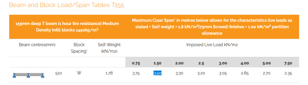
Hi Punloos. It is the depth of the 150mm beams that flagged at my end. Below is a screen shot from the Millbank load span tables. Your imposed load for a domestic floor is 1.5kN/m^2. Beams of this depth are fairly sensitive to deflection, vibration so that made me wonder. Also, as you have plenty floor depth to work with I wondered why the beams were so shallow in depth. Just to get a feel for this you can see that a 150mm beam will give you a rough span of 3.5m (11 -12 feet), you may be able to squeeze a bit more if you reduce the dead load (srceed etc).. but at conceptual stage you don't want to be cutting things too fine as you have to deal with service openings, stair wells maybe and the odd point load. Your starting point here is to look at the largest span you have, that may be in a big open plan area. Next look at the most common span.. say the main bedrooms. Then for beam and block look at what depth of beam will suit most rooms. Off the back of that you can develop up your sound insulation and any fire protection. Next have a look at how you deal with the large span and how you may detail / design this. You also want to have a look at the walls and found construction just to check you have not backed the wrong horse in terms of capacity to support the loads, thermal bridging and acoustic detailing. @Thorfun"True, or just maybe wrap the sound insulating material around the kid rather than in the floor? " Love to see you exploring all the design options.
-
Yes keep it inside. Actually, if you take your time and condition it then you'll get a dividend as it will tend to move less once installed. Follow Temps advise. If it was me I would also every 2-3 weeks turn the planks. Here you start at the top of the pile. Take the first plank off the top outer edge of the pile, turn it so the bottom is now on the top and place it on a good thick spacer where you think the middle of the new timber stack will be. Keep it well clear of the floor, lets the air in. The idea here is that you are taking the timber from the ouside of the stack and placing it in the middle and at the bottom where the weight of the stuff above helps gently keep it more true . Also you are aiming to dry / condition the whole stack evenly thus the reason for moving the outer planks to the middle of the stack. As you do this, check it is being kept clean and so on. Lastly keep the timber spacers a bit long then cover the stack with something breatheable, say a dust sheet, not plastic. The longer spacers keep the sheet away from the timber. Leave a gap at the bottom to let the air flow freely. Every now and again check to see if you need to add a bit of ballast to the top of the stack. Be careful as Temp says about marking the timber with too much weight/ ballast. Depending on the plank thickness maybe look at spacers 600 - 900 mm apart.
-
Hello David. Yes once I started writing it started to grow arms and legs! Again for simplicity I copy and past, respond in line. Please excuse my spelling grammer, I'm just jotting down my thoughts. Thank you for that detailed response. I gather then that the architect does add value by giving me insurance if something goes wrong with the contractor. Think about getting a formal contract in place here. Roughly: If your designer is supervising the workmanship, authorising the staged payments to the builder, that the work is up to scratch, the correct materials have been brought to site, looked after and installed correctly then they are generally liable for your money. It's a big ask hence the fee ~ 25% I mentioned earlier. Also, when you take on this professional role you have to wear a different hat. Many folk on BH employ Designers to bat for their side, say with the Planners. But when you manage/ supervise / sign off on a job you have to be fair and equitable to "The Client" and the "Contractor" Often there is conflict and this takes time and effort to manage these relationships..and that costs money, particularly as it's not that much fun to be in the middle of two sets of folk that often don't see eye to eye. If the builder goes bust and the designer has spent (signed off on) more of your money than they should have then they are liable for the differance. What they are not liable for example is the cost you may incurr if the builder does go bust and the new one charges you more, provided that the due dillegance financial checks have been carried out. Yes you often have a retention / you can get a bond et.. but you can see the cost of this is escalating. In summary if your designer gives you good advise, puts a good (industry recognised) contract in place and steps up to the plate liability wise then you get some protection. Given what you have posted it seems to me that your designer wants to have the fee with limited liability. Is it also fair to say if I find a good contractor to begin with the contractor would have skills to work around building control without the need of the architect. Yes they will but they will also work around you too so logic then dictates that they are not a good responsible contractor. If they are willing to con BC what stops them conning you? Do you think that just because you are paying the bill they will look after you.. they are there to make money! Maybe you won't get what you think you are paying for. Many of the building regs are really good, sensible, they keep us safe and maintain the value of our property when you sell on or borrow against it. You get a few folk bending the rules too far, even on BH! How I view it is if the Architect is recommending contractors that they have worked with before they must have had positive experiences with them in the past to continue using them. So if I go direct to the same contractors as the architect has used previously I should expect plain sailing ahead? No. Go out and get some independant quotes, if they are high / too low phone up the folk and ask why they are so high / low. Gather that info and go back to your Architect. Ask for an explanation. If you do this then you could win a watch by getting a builder via the Architect at a fair negotiated price. Don't try and go behind the Architect's back by going direct.. they will probably find you out within 24 hours and you will have lost any moral high ground. In fact the cost may go up as they may look at you as some chancer, of course forgetting any hypocrisy they may be indulging in themselves. Is it possible for me to purchase an off the shelf contract template that I could complete with the contractor cutting out the architect? Yes see link below for some pointers. https://www.jctltd.co.uk/product/building-contract-for-a-home-owner-occupier Also, see lots of advice on the internet... but at 120K you are taking a chance. I would put in a lot of work into your research on the risk / cost benefit. When first speaking with the architect I was given the RIBA plan of work. But I have not heard anything about CDM regulations. Ah.. have a look at the HSE website for home owners etc. As an overview as soon as an Architect / Designer steps into the world of supervision, tendering etc then they are well within the CDM regs. Your designer has made suggestions regarding selection of contractors.. by now they should be flagging this stuff up to you, a term " Principle Designer" is a key word with some paper work that explains how all this fits together. I think I would be more comfortable if I could negotiate with the architect the 12% fee @ a fixed £100k as that was the original budget. If my quotes come back at £130k I save the 12% on the £30k. I would take a step back here, get some independent quotes, post more questions on BH, maybe some drawings. Plenty folk here that know their stuff. BH is also poplulated by a fair handful of Contractors, Architects, SEs, experienced DIY folk that probably know what is a good price for your area. Lastly, hope this gives you some food for thought and helps you on your way.
-
What about the doors to the room? If you have kids then they need the toilet and leave their bedroom door open, when we get a bit older we like to go to the bog as the bathroom window has the best view of the moon. The internal doors get opened and left so unless they are teenagers and never come out the room, so who cares if they hear what you are listening to? If you are entertaining then if your pals "like a drink" they too open doors, some will even leave the bog door open.. maybe best not to invite them back? Unless you are say a professional musician or are sensitive to noise (I'm pretty deaf) then I would make sure that if you are self building you don't get carried away with this level of internal sound insulation, the time (labour) and cost implications unless you have plenty cash. If you have that amount of cash you can afford a comprehensive redesign. Material prices etc are going through the roof at the moment. Many homes change.. you may have kids.. they go..but more than likely the noise from outside will increase over time and that could be something that you maybe want to future proof for? rather than the short term. Being blunt if you do come to sell then a buyer will be much more interested in what they can hear from outside rather than in between the rooms as you won't be having a party when you are selling the house. If it is a "forever home" then you maybe want to look long term.. maybe spend more on the envelope insulation, the quality of the roof and weathering details? In this climate as a renovator / self builder it may be worth just hedging your bets on the fabric that will add real easily measurable value. In other words the stuff a valuer will appreciate. Your big speakers.. maybe an extra fiver on the valuation. Do you have bifold doors? If so bet you have a lot of frame / vs glass area. For an extra say £ 1500 - 2000 quid you could get some true sliding doors (not the lift and slide type with the massive handle) with a 20 mm thick mullion.. you are as close to frameless glazing as you can get here.. value wise? each to their own but a buyer will appreciate maybe more than a bit of noise between the rooms?
-
Hi David. I have copied you text in italic and comment in line. Hope this helps a bit and maybe others too. I am about to go out to tender on a revised house extension with a budget of roughly £120k which will include significant garden works. I have already paid the architect for full building control approval which has passed. The level of drawing detail for building control approval is often only sufficient for the purpose of obtaining approval and often falls short of the detail required from a full set of detailed construction drawings, call these the builder's working drawings. In Scotland for example I have seen council "warrant drawings" (~ BC drawings England) that just quote clauses in the regs to the effect that x has to comply with reg y. Gets the approval but unless you and the builder, know the regs and how to comply with them then..it's a lottery. I have arranged for the architect to "project manage the build", for which they charge 12% (10% + 2% VAT). No where do does the architect actually say that they will project manage the build. This all sounds a bit vague. Your Architect/ Designer should have explained to you the various options you have and outlined the standard forms of JCT contract for example that are suitable for a domestic 120k project. Below is a link that may help give some clarity and a few pointers to finding what suits you. https://www.jctltd.co.uk/product/building-contract-and-consultancy-agreement-for-a-home-owner-occupier What their job will involve will be being the go between between myself and the main contractor. Their role on site will be to make sure the contractor follows their plans correctly and uses the materials they have specified. They are missing the financial side of things and with their percentage fee do not have much motivation to help keep costs down. I have already spent a considerable sum with the architect especially with the changes I have made with the plans. As a rough rule of thumb if say you are doing an extension at 120k. I'm guessing David, but say you are taking the back off the house and extending.. so it's not just a big box built onto the back of the house ( bit more complex.. rewiring inside the old house and so on) then say ball park ~10 -12% for the Design and SE for the steel work other bits and bobs, and most importantly a good set of SE details. Now to do a full set of construction details, tender this on behalf of the Client, administer the contract (take care of your money, programme), supervise the quality of the work (old Clerk of works function), be on hand to jump to site to resolve technical issues, sign it off as ok, then you can double this to 25%. Now that is a chunk of the budget but in return you pass pretty much most of the liability to the Consultants who pick up the tab if it goes pear shaped.. When you buy a Mercedes with a ten year warranty / personal service consider how much that costs in real terms. There is a significant premium to this reassurance / reducing risk.. say the on board computer won't blow up? they don't blow sparks at most apparently.. they just stop working. My main worry is if I use the architect with their preferred contractors costs will spiral out of control. I feel the architect loves fancy projects and does not seem to pay much attention to actual costs. I had a set budget in mind but towards the end of the design stage the architect informed me that they thought the costs would exceed my budget. In the end I took the decision myself to reduce costs and did a large redesign for which the architect charged me £65 an hour. Your worry is justified. I would mull it over, then work out how to communicate your concerns to the Architect, phone them and back it up with an email. As a word of encouragement don't worry about not "knowing enough" , the law is pretty clear on this as you are a domestic client and it cuts you a bit more slack. I hope that your Architect has been a bit more forthcoming in the detail than your post description. If you want to explore more..then funnily this is much underpinned by the CDM regulations which are to do with safety, but this weaves into how you approach the type of dilemma you face. I get a bit of feedback from Architect's and Designers who are twigging that even when they at say stage 1 or 2 of the RIBA plan of work they are on the hook much more than they realise, and one way they are on the hook is by not communicating effectively with the Client in terms of making mention of the CDM regulations, how information is processed, clarity of / and the correct contract (the standard ones cover this) to ensure the job can be built safely and so on. I hope that this has been touched on and explained to you by your Architect but have not posted here for brevity. The CDM regs apply at concept design stage.. comments welcome. See link below for previous RIBA plan of work. https://www.google.com/search?client=firefox-b-d&q=RIBA+plan+of+work To sum above up, for the extra 10 - 12 % you should be getting all this information at the least, all spelt out in laymans terms. Having spoken with a friend who has had a recent bad experience with a builder they advised me to get a quantity surveyor on board to help keep costs down and for them to negotiate with contractors to make sure contractors were not taking the micky. They advised me to get the whole job priced up with the quantity surveyor before I put it out to tender. They also advised that I should try and lower my fees with the architect if I also bring on a quantity surveyor on board. I do not really want to be paying both an architect and a quantity surveyor as well as the high prices a main contractor is likely to charge. I am wondering what to do. Do I just ditch the architect altogether and get a quantity surveyor to project manage instead? Is there any likely hood the architect will agree to lowering their fees if responsibly is shared with a quantity surveyor? Can a quantity surveyor replace the architect at the build stage as they would likely have a lot of the architect skills but with the added benefit of knowing how much everything will cost. You have already paid your Architect a fee. You could give them a jolt once you have digested the info above. See what happens and get some clarity on what there are offering to do/ extent of liability before you spend more money on other professional fees. Hope this helps give you some food for thought.
-
Hi Mac123. Ah, hind sight is part of life and an intrinsic part of the process. It is very rare that as a designer you sit back (cut yourself some slack Mac), look at the finished job, how it looks, how buildable it was and think.. I got that spot on design wise, at the best price and it was so buildable that we have actually got what we wanted from the builder without a barny. There is always room for raising the standard, tweeking the design on reflection. Also design is often about getting the best compromise. "In hindsight, I should have put insulation in the blue circle and put rebar up through and poured concrete on top, probably would of been the best solution" Yes in an ideal world from an insulation point of view but no from a structural point of view as the balustrade is introducing a bending moment into the concrete. My own view is that simplistically as heat rises you'll get more thermal bridging though your telephone wire than the long convoluted thermal path you show. On the upside what you do have is a good concrete core to post (say resin fix to) fix to and this can open up the opportunity to create a cracking clean detail. It looks like you have quite a good thick concrete core. If your budget can stretch to it then you could maybe cap the wall with a stainless steel plate with intergral drip detail, make the welding a feature. Use counter sunk hex bolts in sleeves to give that "engineered look" for the cap plate. In principle I think this could work but have not done a fag packet calc as yet. The cap plate fixings would be taking a bending force so you need to know a little more about the concrete, thickness and so on. By a clean detail I aslo mean something that looks great Architectutally but also something that is easy to maintain and keep clean.. not gather mould etc. Think about the welding on a motor bike frame, it can be a work of art, no sharp corners to gather dirt. I think with a bit of thought you could do something pretty tidy here. One of the keys is always to check any corner weathering details before you get carried away. Your starting point here is to look at the glazing / glazing fixings you want, post some dimensioned details here and you may get a few ideas on how you it make work from an SE point of view. Once you have that it may be that all the weathing detail falls into place in a simple way. In some ways I'm suggesting you spend more on the balustrade as you see this and less on what is covered. Part of my thought process is driven as I can see that the side plate on your drawing has a much reduced concrete fixing edge distance and the fixing spacing looks questionable. That may be a reason why you're not getting the answers you want SE wise. Also getting all this lined up, and interfacing with the upstand membrane looks problematic.
-
Have a look at the building regs, they have some good diagrams. Also, a lot of councils provide guidance online with easy to understand diagrams. Most of the building regs make great sense and will stop you hurting yourself or visitors unless of course you have been at the neighbours home brew etc. Just follow the regs in terms of rise of step, going / landings and over time you will appreciate it.
-
A live-in builder/contractor?
Gus Potter replied to idontknowwhatiamdoing's topic in General Self Build & DIY Discussion
Hello Idont.. Cracking post. Is that long beach one of the Scottish Islands? It almost looks like a bit of Tiree/ Glensanda way with the whiter sand. As a word of encouragement you will get plenty pointers / advice here from folk that have embarked on this kind of journey. A lot of folk will also make mention of the mistakes they made in the spirit of BH. To get the best out of this then you may wish to post more info. Island location.. ferries etc or just off the beaten track. "Do you think anyone would be interested in this, any ideas where I could find someone up for the task?" Yes, but you to need to give more info to get a focused response. This basic info will set out your practical options. -
Can a slab be too thick to have UFH pipes in it?
Gus Potter replied to Thorfun's topic in Underfloor Heating
Hi Thorfun. Great to see you are getting on with your design team, it's very much a people thing and pays great dividends. How deep do you need to dig into the stone? Of course the scalpings you get out from the dig will make great hardcore! If you have the time you could maybe get some cracking bits of stone for hearths, walls if the bedding planes split off ok. Will cost a bit to explore but using / recycling the stone makes the house a bit special. Oh, and take a few photos if you manage to recover some good stone as if you sell the house you can put this in the brochure and prove the provenance. -
Can a slab be too thick to have UFH pipes in it?
Gus Potter replied to Thorfun's topic in Underfloor Heating
To me the basement slab insulation is continuous mainly with the wall insulation so you don't have a perimeter per say. -
Any need for Structural warranty (no mortgage)
Gus Potter replied to gc100's topic in New House & Structural Warranties
Hello gc100. If you have the right relationship with your SE then you can explore the option that is a little less formal in places. Ask them how much for say two site visits to confirm the structure is build as per the structural drawings. Here for example the SE will formally check the layout, spacing of main members, founds, connections and so on. But in doing so the SE also (should) look at all the other bits and give you a heads up. What I am suggesting is not really recognised under many formal contract conditions that don't include full supervision (call this an old Clerk of works function) but it does work so long as the SE and the Client agree the boundaries of liability. I work on a lot of jobs say where someone wants to take down a couple of load bearing walls, they don't have the funds for a full managed and supervised contract but need a bit of help to deal with the builder. I would rather cast my eye over work just to make sure that it is safe. I take the view that best to do this as then you don't have to worry about a later failure where someone may be hurt. Yes, what I have said may raise a few eyebrows but my PI insurance allows me to be flexible.. but sensible.