le-cerveau
-
Posts
524 -
Joined
-
Last visited
Everything posted by le-cerveau
-
Nope, I don't think so, there was 3-phase right next to our house, we just change from taking one of them to taking all 3 and some re-work to put it underground and keep live for construction.
-
I have 3-phase in the new house, It supplies the Lift (required for my mother) and ASHP (soft start for both) I have also had a 3-phase 16A (22kW) run put into the garage for a future car charging point (as and when required). I also don't have to worry about the power draw from the induction hobs (2 of for split level kitchen).
-

MVHR ducting to outside
le-cerveau replied to Moira Niedzwiecka's topic in Mechanical Ventilation with Heat Recovery (MVHR)
Yes, from Jeremy's experience, all my intakes and exhaust are on the same elevation, roof vents. I don't believe there is a max, but the recommendations is to keep it as short as practicable, the longer the greater the pressure increase (resistance) so the harder the fans have to work to do the same job. -
Not quite sure where you mean with this? Specified by ASHP manufacturer to approve instillation, so I incorporated it into the overall running design.
-
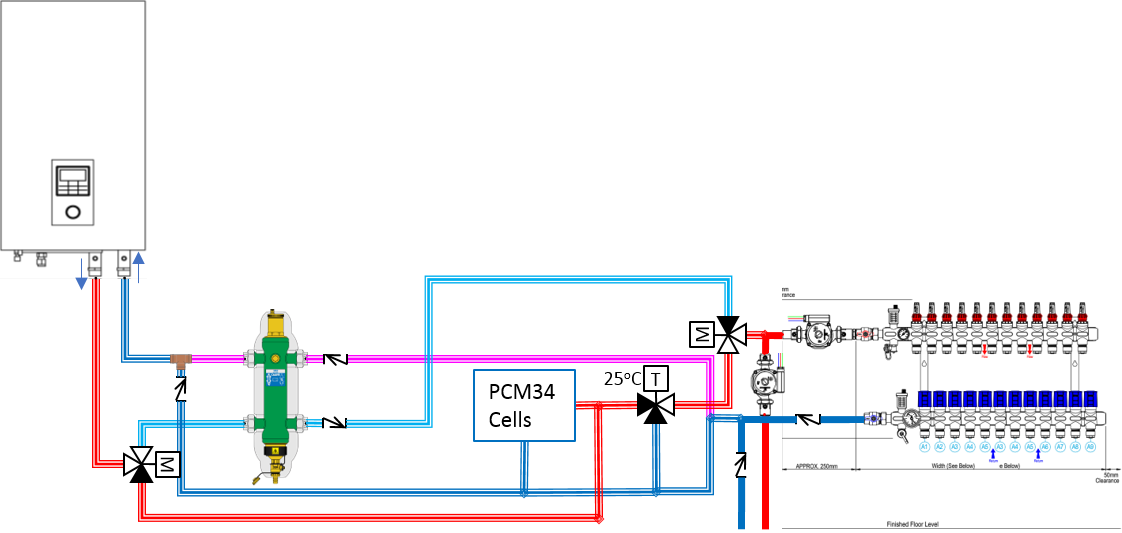
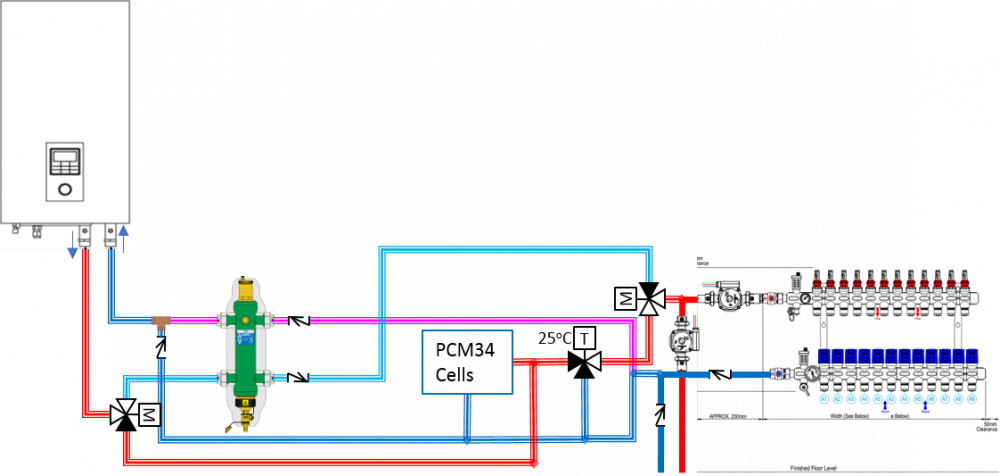
That is not the final setup, this is it: (heating only shown) The ASHP defaults to the Low Loss Header (unless supplying heat), motorised valve controlled by the ASHP. (cooling mode but no call) When drawing heat to the house the other motorised valve connects to the PCM34 cells (via a mixing valve) to draw heat, if the Cells are also calling for heat then the ASHP will also be supplying heat (Valve change over) so heat will come from the ASHP and some into recharging the Cells. When no call for heat (from house) the the motorised valve (controlled by thermostat) sets the flow to the LLH and water simply circulated round the system, may possibly bypass through the ASHP, but but not an issue as when the PCM34 cells call for heat but the house doesn't the ASHP valve isolated the LLH from the ASHP. If the house needs cooling then the ASHP provides cool water to the LLH and it flows on through the UFH pipes. That is the theory anyway!!! (hopefully)
-
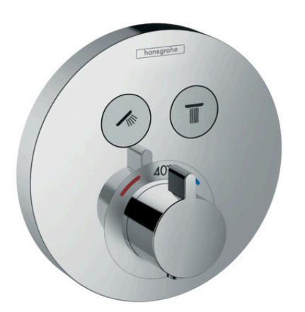
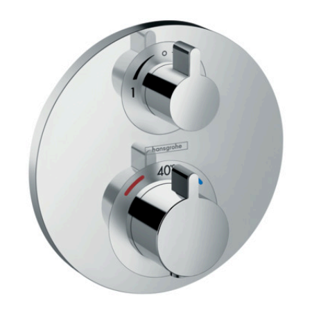
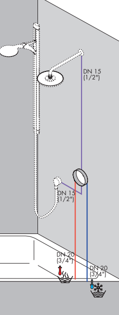
Shower Select S (2 outlet) Ecostat S (2 outlet) iBox install for those valves, you can put the valve anywhere and run the purple outputs to where you want them (within reason)
-
When you say flow, do you mean selection or variable flow rate? I ask as it makes a difference. Not cheap but the Hansgrohe range does what you want, put an ibox where you want the controls, with one output run to the overhead and the other to the output for the handshower. All this is within the wall and the controls go on top, it is fully serviceable. Then select you valve: For on off only control use a Shower Select (one and/or the other) For variable control use an Ecostat (only one at a time)
-
Doesn't surprise me, when my UFH was first designed, I had to tell the company to try again with optimised layouts (only because of this sites predecessor). They just pressed plan on the software and accepted the first output (I suspect), with little/no input from anyone with knowledge experience (and expect to be paid for it).
-
That layout looks non-optimised (ie not spiral counterflow) and just someone putting the pipes down with little/no thought and if I had to hazard a guess there could well be loops over 100m in length!
-
mortgage Timber Kit and Blockwork skin
le-cerveau replied to mikew1978's topic in Self Build Mortgages
I found Buildstore very inflexible when it didn't fit one of their predefined boxes (though I am stuck with them). People here have found going direct to some lenders easier. Ask them to justify 'why' if your plan is an established route with certification, If they want your business (money) they will have to accomodate you. Be warned their inspectors don't understand innovative (mine had never seen/heard of an ICF), i would use other inspection regimes (I ditched them) -
mvhr general question
le-cerveau replied to lizzie's topic in Mechanical Ventilation with Heat Recovery (MVHR)
On my blog there is a picture of them now fully plumbed in and running, even the one at 275m3/h is fairly quiet, audible in the plant room but nowhere else. -
Polished Concrete Flooring
le-cerveau replied to laurenco's topic in General Self Build & DIY Discussion
Not necessarily, depends on your insulation. It will be slower to react the further away from the surface it is, but depending on your house that may/may not be an issue.- 13 replies
-
- 1
-

-
- polished concrete
- inslated floorslab
- (and 4 more)
-
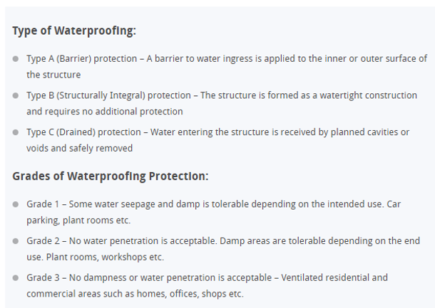
Do you mean Grade 1? I would have thought it should be Grade 3, or at least 2. If you have a Grade 1 system then you will need a Type C to deal with the seepage!
-
Is not the whole point of an ICF basement to eliminate thermal bridging and provide an insulated shell, by opting for a Type C you are introducing thermal bridges and allowing water inside to then pump out. Surely you want to opt for a Type A (Barrier Protection) and provide drainage externally to the basement!
-
You can use loopcad free for a month so time when you download it. You can pretty much use your own logic to work out the best runs as loopcad will manage simple square rooms but anything more complex (round bathtub and toilet...) and it gets a but suspect and you end up manually drawing the loops anyway. It will give you the lengths though.
-
An example of spiral counterflow, the optimum. Of your diagrams the first one is better, as it is counterflow, but you also want to spiral where possible.
-
Rotor units tend to be larger (commercial) type units and need finer control as the rotation of the drum needs to be controlled to optimise heat exchange. Counterflow units are more normal in domestic settings, I actually have 2 x counterflow units in my install (see the blog) >400m2 floor area, so it should be well within the realms of feasibility to do your house with one system. The limit I suspect will be floor area as this gives a supply rate of 86.4 l/s or 311.04 m3/h. Room estracts will not approach this (unless it is all wet rooms!). Agree you don't want the unit running at full capacity but 60-70% is pretty usual, and once you have it set up and inspected you will no doubt reduce the airflow below this rate, as it is unnecessary. The calculations are based on normal (small houses) large ones don't compute. There are plenty of counterflow units in the 400-450m3/h range, giving you ample spare capacity, or the ability to run slower and more efficiently.
-
mvhr general question
le-cerveau replied to lizzie's topic in Mechanical Ventilation with Heat Recovery (MVHR)
These are my units from the stage 1 install, the foil like ones are actually silencers going to the manifolds, which have acoustic dampening in also, the black stuff is EPS ducting and leads to the outside world.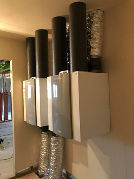
-
Apologies I didn’t take many pictures of the process. Initial Frustrations: Due to a delay in the First Floor (FF) Micro Screed, couldn’t access the house as planned (Thursday after arrival) but had to wait until the following Wednesday, I would have had the balancing complete by the Monday and had a week to do other small jobs, as it was I got the job finished, bit nothing else. First of all I fitted the ground floor vent terminals, this involved trimming the terminal ends level with the plasterboard Fitting the metal connecting terminal with the supplied Tek® Screws and inserting the terminal: Tek® Screws are a pig, you need to predrill the metal to use the effectively and I was using the builders impact driver Makita 18V LTX and it was still hard work. I locked all the terminals in the fully open position and inserted them, hold up and turn to lock in place, these are an update on the spring clip versions as apparently they don’t get a good seal, with the mechanically fixed base plate and a turn to lock valve they are more rigid, true but harder to install! Installed extract valve. Valve removed leaving housing Housing on adaptor. The first picture shows an installed extract terminal in the Airing Cupboard. The second one the metal connector plate (in the Dining Room) with the valve removed. The third one an adaptor plate attached to the duct terminal in a room that will have a suspended ceiling (tiles) so to be finished after all messy work, the duct terminal will be adjusted as required. Then I installed the FF terminals, I had help for this then access to the attic to connect up the external supply and exhaust ducts to the roof terminals, my builders had to cut 2 access holes in the plasterboard (attic already plastered) one to connect the FF supply duct (the attic has insulation between the rafters and below which follows the vertical chords of the attic trusses) so this duct has less insulation that the others but is still in the insulated area. The second to access the FF exhaust manifold, in the same area (but always planned) these will have insulated doors re-fitted. They also had to cut free the exhaust duct for the FF unit which the plasterers had plastered around, half covering (I ask you), ie 180mm circular duct with half the duct (a semicircle) inside plaster, half out! So I connected up the FF units and proceeded with that one, it made it easier accessing the manifolds before installing the GF ducts. We also had to build a small trestle to go over the FF exhaust duct to lie on to work in the exhaust manifold. Next, I fired up the FF unit and set the speed to 275m3/h, this was a challenge as the electrician had to make certain circuits live. In the CU the top Right is the lift (3-Phase) required for install T&C, the bottom 5 (left) are the MVHR and others on the circuit, 2 x downstairs power circuits and 2 others I don’t know and didn’t dig into. A lot of work still to be done there, but I had my power. The two MVHR units connected up (though the drains weren’t connected until Friday). I then did my initial measure, I have purchased a Testo 417 with hoods and UKAS calibration (belt and braces), whether I keep it or sell on, not sure yet. Initial readings gave a total extract of around 275m3/h but supply of nearly 375m3/h, so obviously my systems measure from the extract and just run the supply at the same speed, the calculation showed similar resistances for the system, so I had to adjust the system (use the imbalance) to even out the flows, initially I used a 100m3/h imbalance to even this out (reduced later on). I then proceeded to balance the terminals, as mine is the Ubbink system the balancing is done in the manifolds with restrictor rings, you have either no restrictor, or a restrictor with 0-12 rings removed (0 = max resistance, 12 = almost no restistance). The table below shows room, terminal, design flow rates, calculated restrictors and the final ones I ended up with. Design Flow Rate BR Min Initial Final Final Room m3/h l/s l/s Rings Removed m3/h Rings Removed m3/h l/s m3/h l/s en-suite 2 E1 45 12.5 8 6 6 23.0 6.39 48.6 13.5 en-suite 2 E2 6 6 25.6 7.11 en-suite 3 E3 45 12.5 8 6 6 24.1 6.69 51.3 14.3 en-suite 3 E4 5 6 27.2 7.56 Cistern E10 20 5.6 - - 12.0 3.33 12.0 3.3 Attic EA 25 6.9 6 10 - 22.9 6.36 22.9 6.4 A/C E5 25 6.9 6 5 5 27.9 7.75 27.9 7.8 Bathroom E6 45 12.5 8 4 4 24.2 6.72 48.8 13.6 Bathroom E7 4 4 24.6 6.83 mstr en-suite E8 50 13.9 8 7 7 27.9 7.75 54.7 15.2 mstr en-suite E9 6 6 26.8 7.44 Cistern E11 20 5.6 4 10 12.6 3.50 12.6 3.5 275 76.4 278.8 77.44 As you can see it was reasonably accurate. I had to reduce the resistance to the attic and one cistern and one other terminal, otherwise quite easy. So with the extract done I moved on to the Supply. Initially I went round and totaled up all the supplies and kept adjusting the imbalance until the total supply was about 275m3/h, which was around 70m3/h, then I set to work adjusting the flows: Design Flow Rate BR Min Initial Final Final Room m3/h l/s l/s Rings Removed m3/h Rings Removed m3/h l/s m3/h l/s Bed 2 S1 50 13.9 11 7 26.1 7.25 50.9 14.1 Bed 2 S2 9 6 24.8 6.89 Bed 3 S3 50 13.9 6 - 19.8 5.50 49.0 13.6 Bed 3 S4 5 6 29.2 8.11 Bed 4 S5 50 13.9 7 4 24.0 6.67 49.3 13.7 Bed 4 S6 6 4 25.3 7.03 Bed 5 S7 50 13.9 6 4 24.5 6.81 50.7 14.1 Bed 5 S8 7 5 26.2 7.28 Master Bed S9 50 13.9 - - 24.8 6.89 49.6 13.8 Master Bed S10 9 7 24.8 6.89 Attic SA 25 6.9 9 - 26.2 7.28 26.2 7.3 275 76.4 131.37 275.7 76.58 AS you can see the difference between calculation and actual is huge, take terminal S3, it has a relatively short run (compared to others) yet I had to remove all restriction and could only get 20m3/h, I balanced up the room with S4 but a total mystery. S1 was a significantly long run but require more restriction than calculated. I managed to balance up the system after several hours of too and frow, including slightly adjusting the imbalance to get the system set. The Ground floor was a similar experience, though with some terminals suspended in the air, the measuring hood neatly sealed over these so measurement was not an issue, and in fact I didn’t need a ladder to reach these ones so it made it easier. GF setting was 220m3/h (I actually set 225) and again the extract tallied up but the supply was about 40m3/h over so Imbalance require again. Design Flow Rate BR Min Initial Final Final Room m3/h l/s l/s Rings Removed m3/h Rings Removed m3/h l/s m3/h l/s Kitchen E1 80 22.2 13 - - 44.0 12.22 85.8 23.8 Kitchen E2 7 6 41.8 11.61 Laundry E6 50 13.9 8 4 6 26.6 7.39 50.7 14.1 Laundry E7 3 5 24.1 6.69 en-suite 1 E4 45 12.5 8 2 6 27.7 7.69 51.4 14.3 en-suite 1 E5 2 7 23.7 6.58 WC E3 25 6.9 6 3 5 26.1 7.25 26.1 7.3 Cistern E8 20 5.6 1 - 11.0 3.06 11.0 3.1 220 61.1 225.0 62.50 Again extract calculation and actual weren’t miles apart, except from I had to remove all restriction from the cistern extract, and subsequently most of the others to balance it out but relatively easy and logical. Design Flow Rate BR Min Initial Final Final Room m3/h l/s l/s Rings Removed m3/h Rings Removed m3/h l/s m3/h l/s Lounge (1) S1 50 13.9 9 4 25.7 7.14 51.8 14.4 Lounge (2) S2 7 - 26.1 7.25 Dining S3 30 8.4 - 3 30.1 8.36 30.1 8.4 Front Hall S8 25 6.9 9 3 26.2 7.28 26.2 7.3 Bed 1 (1) S6 45 12.5 6 12 22.1 6.14 45.6 12.7 Bed 1 (2) S7 6 0 23.5 6.53 Study 1 S5 35 9.7 12 1 35.8 9.94 35.8 9.9 Study 2 S4 35 9.7 - 2 36.1 10.03 36.1 10.0 220 61.1 131.37 225.6 62.67 Supply was another question, nearly a whole day to get this right: Study 2, the longest run yet only 2 rings removed, same for study 1. The Bedroom similar runs one with full restriction and one with almost none. The lounge S1 in longer than S2 though has more restriction required, nothing made sense, eventually balanced, but no rational explanation as to why. The only think I can think of (and this applies to the First Floor) the calculation programme works for the extract system, but for supply, the location of the duct on the manifold has a huge impact on the initial resistance and flow rates. Advice for balancing when doing this go for bold alterations in restriction, I kept nibbling on the GF and have ended up with lots of spare restrictors of various sizes, instead of a load of complete (new) ones. The final thing I did was remove all the vent terminals so the builders could fill in the larger holes and the painters get on with the final job.
-
I do wear thermals whilst walking. My wife has a big North Face coat, It is like a duvet and she get hot in it.
-
Polished Concrete Flooring
le-cerveau replied to laurenco's topic in General Self Build & DIY Discussion
We went for screed (Builders choice), we have 250mm concrete slab (Ground Floor) and 250mm concrete beams (First Floor). Then 50mm liquid screed with the UFH pipes in, thicker on the First Floor due to camber of the 8m span beams, then another 50mm liquid screed on top (ducted electric cables in this one). Teh screed was laid in 2 runs on advice to improve curing. It is then topped with a microscreed finish this is the final floor surface (currently doing the Ground Floor). I know completely over the top, but it works, the builders had structural concrete to work from for a long time, the screed was next, then plastering and the Micro Screed is the final work, just finishing off the second fix to go and the wood work (doors, skirting,...)- 13 replies
-
- 1
-
-
- polished concrete
- inslated floorslab
- (and 4 more)
-
I walked to work in -19 this morning (standard) but I am in Latvia (proper Baltic!) It get up to -11 during the day and in other areas -30 is standard, Riga is fairly mild.
-
Our builders put the stud up as soon as possible, UFH, screed, everything else went in afterwards. This allowed first fix to take place for all trades, electrical, plumbing, MVHR (me), it was easy for people to visualise where they were and what need to go where. I big empty room may be tempting but where exactly is the drop for teh sockets/light switches, how far in from the wall is that vent terminal.....
-
Log burner
le-cerveau replied to jpinthehouse's topic in Mechanical Ventilation with Heat Recovery (MVHR)
When we initially designed our house we had a wood burner, mainly because the in 'laws do, however theirs is a leaky old end of terrace (knock through) house, and they have over an acre of land with trees so source all their own wood, incidentally they overheat when it is lit. As our design matured and I did more reading (on our predecessor) I realised that it was a nice idea but totally unnecessary in the house we were building, along with other things (individual room thermostats/.....) I think wood burners are an impulse buy/fad that when look at in the cold light of day totally inappropriate for most people. There will always be situations that they do work (location, house, fuel supply) as no one solution fits all but most definitely not required in urban/city environments (just look at the fuel supply logistics). -
I think what nick means is use the DHW coil (Circuit) as the ASHP brine circuit (primary water) then just draw heat directly out of the tank.