


Entry posted by le-cerveau
2520 views
Apologies I didn’t take many pictures of the process.
Initial Frustrations:
Due to a delay in the First Floor (FF) Micro Screed, couldn’t access the house as planned (Thursday after arrival) but had to wait until the following Wednesday, I would have had the balancing complete by the Monday and had a week to do other small jobs, as it was I got the job finished, bit nothing else.
First of all I fitted the ground floor vent terminals, this involved trimming the terminal ends level with the plasterboard
Fitting the metal connecting terminal with the supplied Tek® Screws and inserting the terminal:
Tek® Screws are a pig, you need to predrill the metal to use the effectively and I was using the builders impact driver Makita 18V LTX and it was still hard work. I locked all the terminals in the fully open position and inserted them, hold up and turn to lock in place, these are an update on the spring clip versions as apparently they don’t get a good seal, with the mechanically fixed base plate and a turn to lock valve they are more rigid, true but harder to install!
 Installed extract valve. Valve removed leaving housing Housing on adaptor.
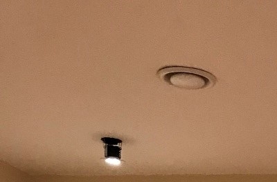
The first picture shows an installed extract terminal in the Airing Cupboard.
The second one the metal connector plate (in the Dining Room) with the valve removed.
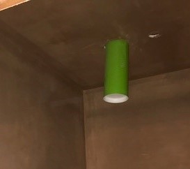
The third one an adaptor plate attached to the duct terminal in a room that will have a suspended ceiling (tiles) so to be finished after all messy work, the duct terminal will be adjusted as required.
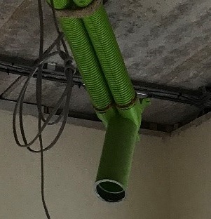
Then I installed the FF terminals, I had help for this then access to the attic to connect up the external supply and exhaust ducts to the roof terminals, my builders had to cut 2 access holes in the plasterboard (attic already plastered) one to connect the FF supply duct (the attic has insulation between the rafters and below which follows the vertical chords of the attic trusses) so this duct has less insulation that the others but is still in the insulated area. The second to access the FF exhaust manifold, in the same area (but always planned) these will have insulated doors re-fitted. They also had to cut free the exhaust duct for the FF unit which the plasterers had plastered around, half covering (I ask you), ie 180mm circular duct with half the duct (a semicircle) inside plaster, half out! So I connected up the FF units and proceeded with that one, it made it easier accessing the manifolds before installing the GF ducts. We also had to build a small trestle to go over the FF exhaust duct to lie on to work in the exhaust manifold.
Next, I fired up the FF unit and set the speed to 275m3/h, this was a challenge as the electrician had to make certain circuits live.

In the CU the top Right is the lift (3-Phase) required for install T&C, the bottom 5 (left) are the MVHR and others on the circuit, 2 x downstairs power circuits and 2 others I don’t know and didn’t dig into. A lot of work still to be done there, but I had my power.
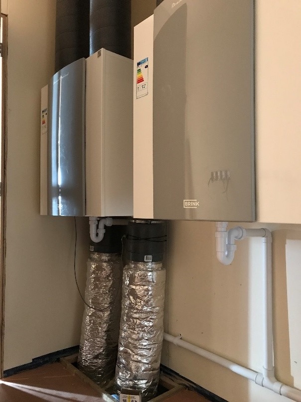
The two MVHR units connected up (though the drains weren’t connected until Friday).
I then did my initial measure, I have purchased a Testo 417 with hoods and UKAS calibration (belt and braces), whether I keep it or sell on, not sure yet.
Initial readings gave a total extract of around 275m3/h but supply of nearly 375m3/h, so obviously my systems measure from the extract and just run the supply at the same speed, the calculation showed similar resistances for the system, so I had to adjust the system (use the imbalance) to even out the flows, initially I used a 100m3/h imbalance to even this out (reduced later on). I then proceeded to balance the terminals, as mine is the Ubbink system the balancing is done in the manifolds with restrictor rings, you have either no restrictor, or a restrictor with 0-12 rings removed (0 = max resistance, 12 = almost no restistance).
The table below shows room, terminal, design flow rates, calculated restrictors and the final ones I ended up with.
|
Design Flow Rate |
BR Min |
Initial |
Final |
Final |
||||||||
|
Room |
m3/h |
l/s |
l/s |
Rings Removed |
m3/h |
Rings Removed |
m3/h |
l/s |
m3/h |
l/s |
||
|
en-suite 2 |
E1 |
45 |
12.5 |
8 |
6 |
|
6 |
23.0 |
6.39 |
48.6 |
13.5 |
|
|
en-suite 2 |
E2 |
6 |
|
6 |
25.6 |
7.11 |
||||||
|
en-suite 3 |
E3 |
45 |
12.5 |
8 |
6 |
|
6 |
24.1 |
6.69 |
51.3 |
14.3 |
|
|
en-suite 3 |
E4 |
5 |
|
6 |
27.2 |
7.56 |
||||||
|
Cistern |
E10 |
20 |
5.6 |
|
- |
|
- |
12.0 |
3.33 |
12.0 |
3.3 |
|
|
Attic |
EA |
25 |
6.9 |
6 |
10 |
|
- |
22.9 |
6.36 |
22.9 |
6.4 |
|
|
A/C |
E5 |
25 |
6.9 |
6 |
5 |
|
5 |
27.9 |
7.75 |
27.9 |
7.8 |
|
|
Bathroom |
E6 |
45 |
12.5 |
8 |
4 |
|
4 |
24.2 |
6.72 |
48.8 |
13.6 |
|
|
Bathroom |
E7 |
4 |
|
4 |
24.6 |
6.83 |
||||||
|
mstr en-suite |
E8 |
50 |
13.9 |
8 |
7 |
|
7 |
27.9 |
7.75 |
54.7 |
15.2 |
|
|
mstr en-suite |
E9 |
6 |
|
6 |
26.8 |
7.44 |
||||||
|
Cistern |
E11 |
20 |
5.6 |
|
4 |
|
10 |
12.6 |
3.50 |
12.6 |
3.5 |
|
|
275 |
76.4 |
|
278.8 |
77.44 |
||||||||
As you can see it was reasonably accurate. I had to reduce the resistance to the attic and one cistern and one other terminal, otherwise quite easy.
So with the extract done I moved on to the Supply. Initially I went round and totaled up all the supplies and kept adjusting the imbalance until the total supply was about 275m3/h, which was around 70m3/h, then I set to work adjusting the flows:
|
Design Flow Rate |
BR Min |
Initial |
Final |
Final |
||||||||
|
Room |
m3/h |
l/s |
l/s |
Rings Removed |
m3/h |
Rings Removed |
m3/h |
l/s |
m3/h |
l/s |
|
|
|
Bed 2 |
S1 |
50 |
13.9 |
|
11 |
|
7 |
26.1 |
7.25 |
50.9 |
14.1 |
|
|
Bed 2 |
S2 |
9 |
|
6 |
24.8 |
6.89 |
|
|||||
|
Bed 3 |
S3 |
50 |
13.9 |
|
6 |
|
- |
19.8 |
5.50 |
49.0 |
13.6 |
|
|
Bed 3 |
S4 |
|
5 |
|
6 |
29.2 |
8.11 |
|
||||
|
Bed 4 |
S5 |
50 |
13.9 |
|
7 |
|
4 |
24.0 |
6.67 |
49.3 |
13.7 |
|
|
Bed 4 |
S6 |
6 |
|
4 |
25.3 |
7.03 |
|
|||||
|
Bed 5 |
S7 |
50 |
13.9 |
|
6 |
|
4 |
24.5 |
6.81 |
50.7 |
14.1 |
|
|
Bed 5 |
S8 |
|
7 |
|
5 |
26.2 |
7.28 |
|
||||
|
Master Bed |
S9 |
50 |
13.9 |
|
- |
|
- |
24.8 |
6.89 |
49.6 |
13.8 |
|
|
Master Bed |
S10 |
|
9 |
|
7 |
24.8 |
6.89 |
|
||||
|
Attic |
SA |
25 |
6.9 |
|
9 |
|
- |
26.2 |
7.28 |
26.2 |
7.3 |
|
|
275 |
76.4 |
131.37 |
|
|
275.7 |
76.58 |
|
|||||
AS you can see the difference between calculation and actual is huge, take terminal S3, it has a relatively short run (compared to others) yet I had to remove all restriction and could only get 20m3/h, I balanced up the room with S4 but a total mystery. S1 was a significantly long run but require more restriction than calculated. I managed to balance up the system after several hours of too and frow, including slightly adjusting the imbalance to get the system set.
The Ground floor was a similar experience, though with some terminals suspended in the air, the measuring hood neatly sealed over these so measurement was not an issue, and in fact I didn’t need a ladder to reach these ones so it made it easier.
GF setting was 220m3/h (I actually set 225) and again the extract tallied up but the supply was about 40m3/h over so Imbalance require again.
|
Design Flow Rate |
BR Min |
Initial |
Final |
Final |
|||||||||
|
Room |
m3/h |
l/s |
l/s |
Rings Removed |
m3/h |
Rings Removed |
m3/h |
l/s |
m3/h |
l/s |
|
||
|
Kitchen |
E1 |
80 |
22.2 |
13 |
- |
|
- |
44.0 |
12.22 |
85.8 |
23.8 |
|
|
|
Kitchen |
E2 |
7 |
|
6 |
41.8 |
11.61 |
|
||||||
|
Laundry |
E6 |
50 |
13.9 |
8 |
4 |
|
6 |
26.6 |
7.39 |
50.7 |
14.1 |
|
|
|
Laundry |
E7 |
3 |
|
5 |
24.1 |
6.69 |
|
||||||
|
en-suite 1 |
E4 |
45 |
12.5 |
8 |
2 |
|
6 |
27.7 |
7.69 |
51.4 |
14.3 |
|
|
|
en-suite 1 |
E5 |
2 |
|
7 |
23.7 |
6.58 |
|
||||||
|
WC |
E3 |
25 |
6.9 |
6 |
3 |
|
5 |
26.1 |
7.25 |
26.1 |
7.3 |
|
|
|
Cistern |
E8 |
20 |
5.6 |
|
1 |
|
- |
11.0 |
3.06 |
11.0 |
3.1 |
|
|
|
220 |
61.1 |
225.0 |
62.50 |
|
|||||||||
Again extract calculation and actual weren’t miles apart, except from I had to remove all restriction from the cistern extract, and subsequently most of the others to balance it out but relatively easy and logical.
|
Design Flow Rate |
BR Min |
Initial |
Final |
Final |
|||||||||
|
Room |
m3/h |
l/s |
l/s |
Rings Removed |
m3/h |
Rings Removed |
m3/h |
l/s |
m3/h |
l/s |
|||
|
Lounge (1) |
S1 |
50 |
13.9 |
|
9 |
|
4 |
25.7 |
7.14 |
51.8 |
14.4 |
||
|
Lounge (2) |
S2 |
7 |
|
- |
26.1 |
7.25 |
|||||||
|
Dining |
S3 |
30 |
8.4 |
|
- |
|
3 |
30.1 |
8.36 |
30.1 |
8.4 |
||
|
Front Hall |
S8 |
25 |
6.9 |
|
9 |
|
3 |
26.2 |
7.28 |
26.2 |
7.3 |
||
|
Bed 1 (1) |
S6 |
45 |
12.5 |
|
6 |
|
12 |
22.1 |
6.14 |
45.6 |
12.7 |
||
|
Bed 1 (2) |
S7 |
6 |
|
0 |
23.5 |
6.53 |
|||||||
|
Study 1 |
S5 |
35 |
9.7 |
|
12 |
|
1 |
35.8 |
9.94 |
35.8 |
9.9 |
||
|
Study 2 |
S4 |
35 |
9.7 |
|
- |
|
2 |
36.1 |
10.03 |
36.1 |
10.0 |
||
|
220 |
61.1 |
131.37 |
|
225.6 |
62.67 |
||||||||
Supply was another question, nearly a whole day to get this right: Study 2, the longest run yet only 2 rings removed, same for study 1. The Bedroom similar runs one with full restriction and one with almost none. The lounge S1 in longer than S2 though has more restriction required, nothing made sense, eventually balanced, but no rational explanation as to why.
The only think I can think of (and this applies to the First Floor) the calculation programme works for the extract system, but for supply, the location of the duct on the manifold has a huge impact on the initial resistance and flow rates.
Advice for balancing when doing this go for bold alterations in restriction, I kept nibbling on the GF and have ended up with lots of spare restrictors of various sizes, instead of a load of complete (new) ones.
The final thing I did was remove all the vent terminals so the builders could fill in the larger holes and the painters get on with the final job.
-
 1
1
-
 1
1
2 Comments
Recommended Comments
Create an account or sign in to comment
You need to be a member in order to leave a comment
Create an account
Sign up for a new account in our community. It's easy!
Register a new accountSign in
Already have an account? Sign in here.
Sign In Now