Nick Laslett
-
Posts
687 -
Joined
-
Last visited
-
Days Won
1
Everything posted by Nick Laslett
-
I used Tyvek Housewrap for my dormers. This is classed W1 - extremely water resistant. It looks like they used Permavent for your dormer, this is also classified W1 - extremely water resistant. https://www.permavent.co.uk/products/permavent-max-all-zones/ Also your choice of cladding looks pretty robust to driving rain. I’m sure there is more that could have been done. But I don’t think felt was necessary.
-
LoopCAD is professional software for modelling UFH systems. It covers the heat loss process and is very thorough. https://www.avenir-online.com/AvenirWeb/LoopCAD/LoopCADHome.aspx It has a 30 day free trial. But still has some functions after the trial period. My output from Jeremy’s spreadsheet and LoopCAD agreed with each other.
-
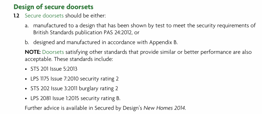
I’m pretty sure your front door, back door and downstairs windows all need to be Document Q compliant. Which essentially means PAS24. The various standards overlap each other and are pretty circular. This cover frames, locks and glass. I would expect it to also be a requirement of your warranty provider. And in the longer term could be a feature of your home insurance cover.
-
I feel your pain. Until the house has been finished and you have gone through a full year’s weather, it is very hard to model in advance how it will perform. Even the HeatGeek YouTuber casually mentions in one of his detailed ASHP videos that you will have to adjust the weather compensation when the cold weather arrives to get it right for your dwelling, if you install the ASHP in summer. After reading many threads here on the topic, I feel that short cycling is the main factor you want to engineer our with good design. I’m sure the heat loss tools are good, but you will find a big difference between the PHPP model and the defaults in SAP. It is a lot of effort to model the window junction heat losses accurately. My understanding is that constant short cycling will wear you ASHP quickest. I wonder where your installer stands on the Legionnaires weekly boost program?
-
The 63mm ducting has string lines. The trick: Plastic bag and an air blower. Tie string to bag and use it a bit like a parachute. The air blower doesn’t even need to be that powerful. We used this in blower mode: https://makitauk.com/product/dvc750lz Here is an example using a Henry to suck the bag down the duct.
-
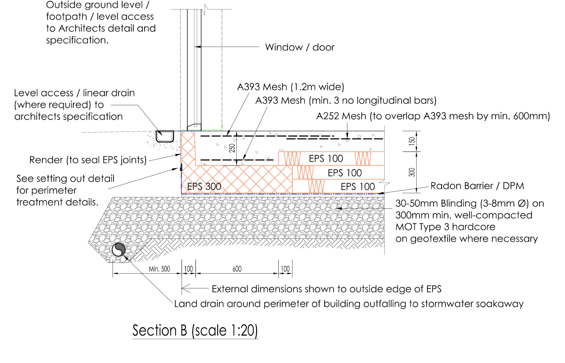
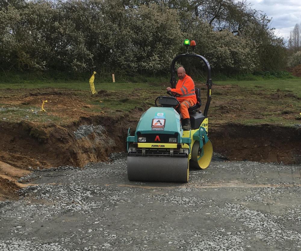
I believe that the 110mm corrugated twin walled ducting can take a lot of weight. The spec sheet says 450N. I don't know what that means, but my ground workers did not seem that worried. The ducting was under the MOT. https://unitedcivilssupplies.co.uk/wp-content/uploads/2020/03/naylor-ducting-coil-data-sheet.pdf Here is the roller they used, I think it was 1.5 tonne. I think the vibration is the most important aspect of the roller not the actual weight. The Structural Engineer gave the following instruction: "Ride-On" vibrating roller - max layer depth = 150mm "Walk behind" vibrating roller - max layer depth = 100mm So they had to roller the MOT at 150mm, then add the 2nd 150mm layer and roll again.
-
My ground works crew had never done an insulated raft, so we did encounter one problem. The Surveyor did the setting out and put in all the pegs to marks the SVP pipes, etc, before the ground workers did their excavations, which disturbed all the pegs. We had to have the Surveyor come back and set out a second time. For an insulated foundation you need to cut out a flat platform for the foundations and then get the setting out done.
-
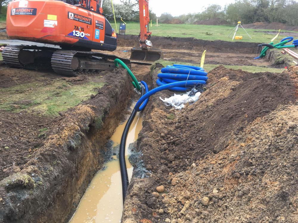
We had an electrical kiosk on the perimeter of the site where the service entered the plot. Services trench.

-
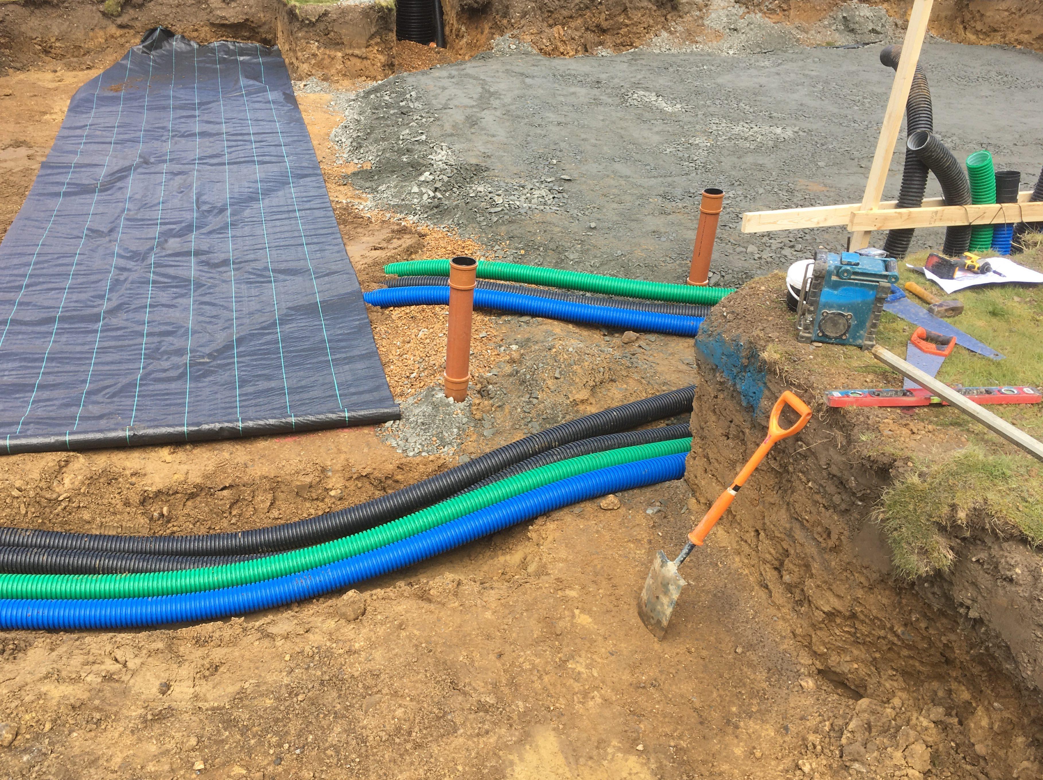
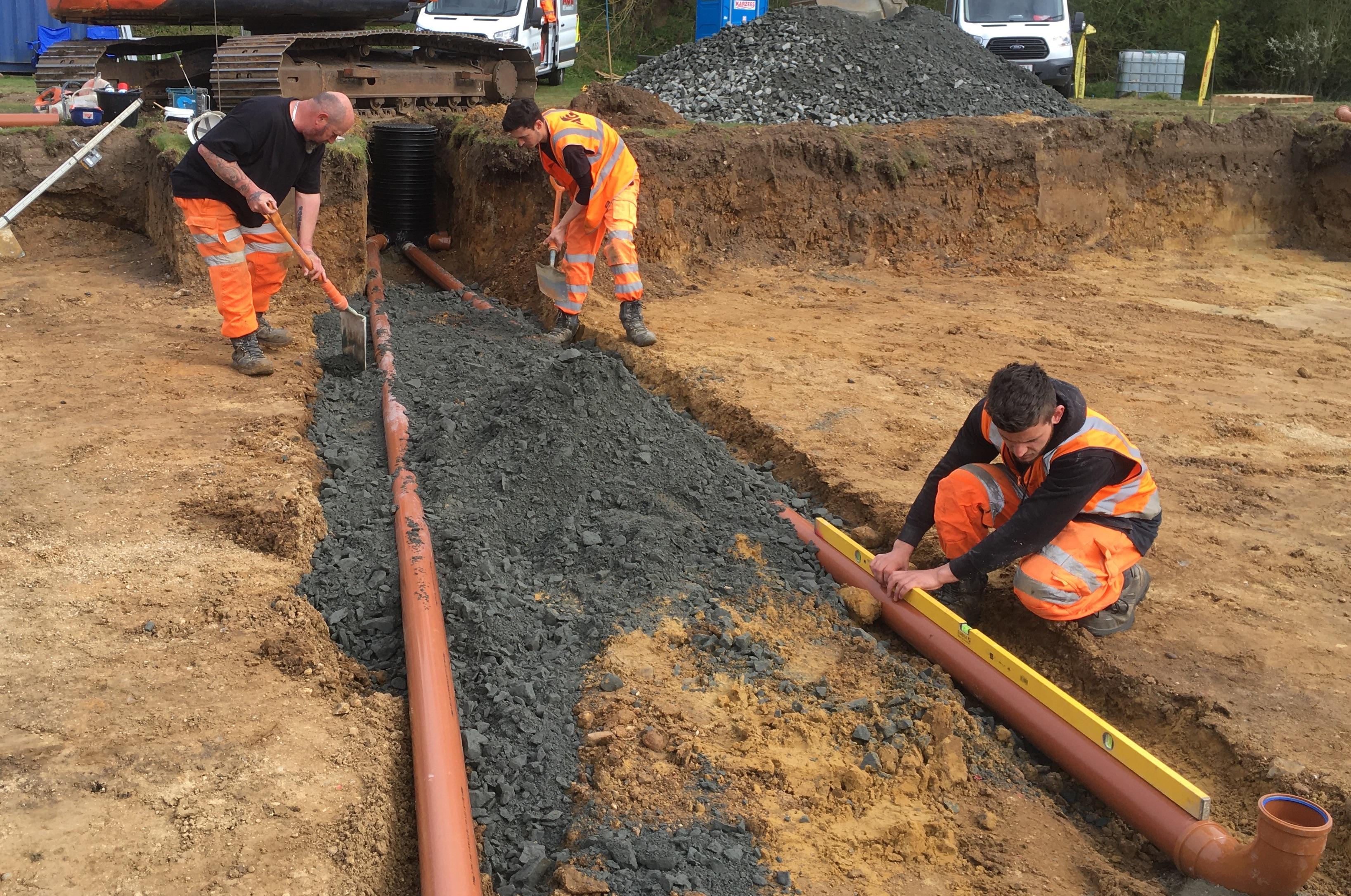
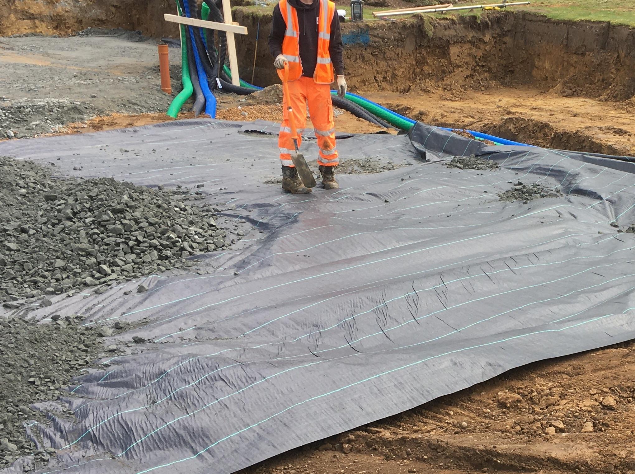
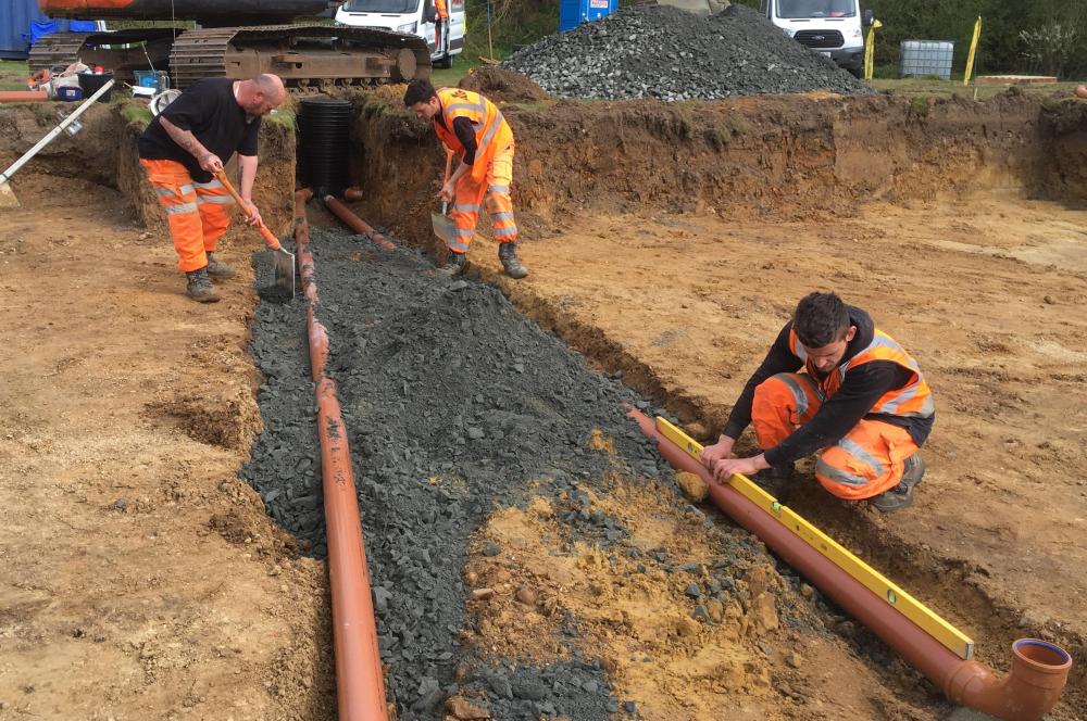
A few more photos. Drainage being laid under the MOT Type 3. A cross section with geotextile, MOT Type 3 and ducts underneath.

-
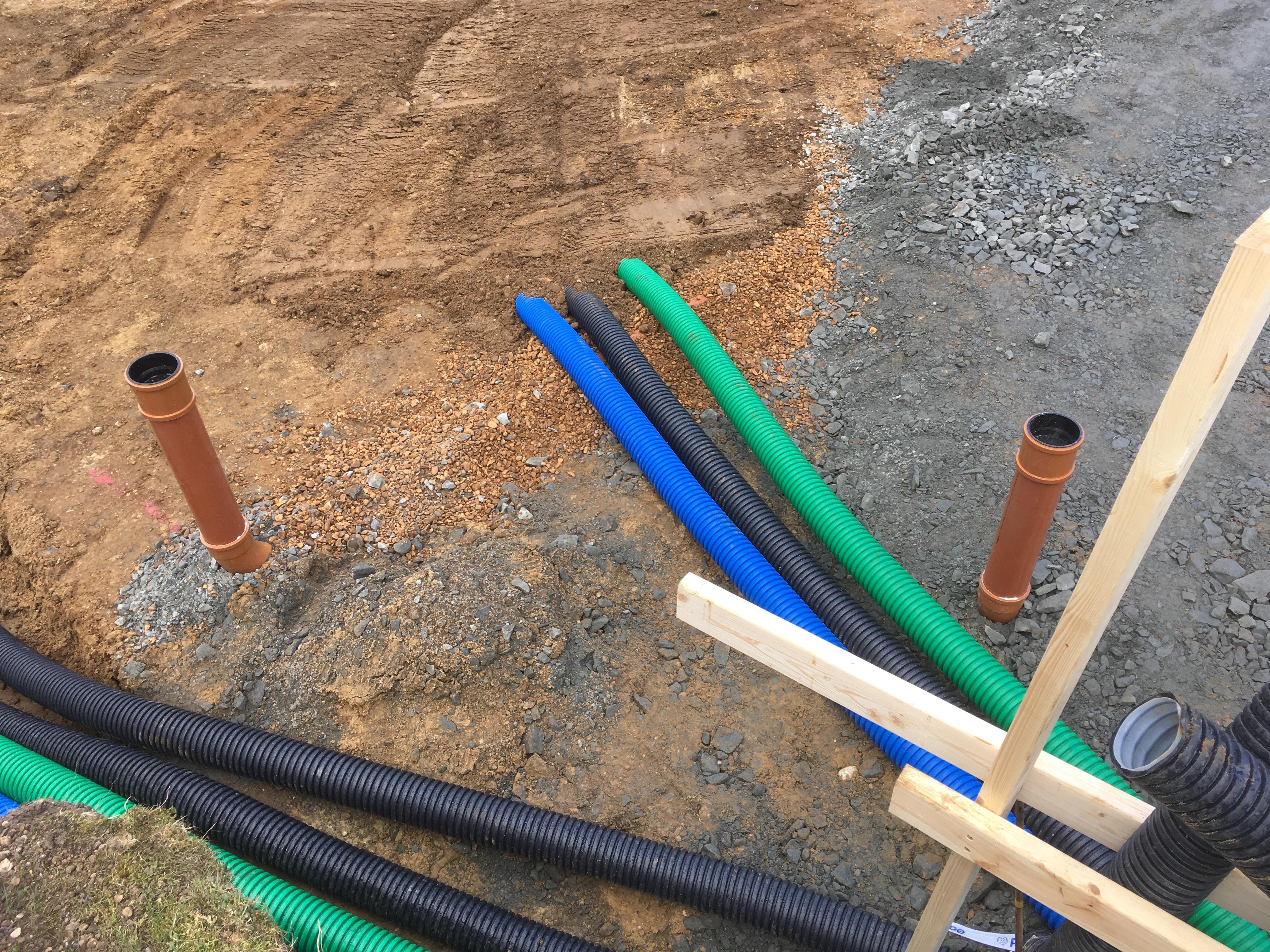
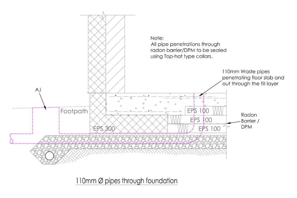
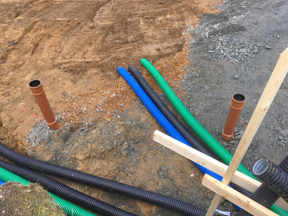
Here are some details for the SVP from my foundation detail. Also a site photo. All of the services were in 110mm coloured ducting under the sub base in trenches in the ground about 900mm deep. We laid the insulated ASHP pipe in the MOT layer. Our build up was 300mm MOT type 3, with 50mm of sand, then 300mm EPS, then 150mm concrete. My groundworks guys were very clear on what was needed. We had some 63mm ducting for electrical cabling leaving the house to the Sewage Treatment Plant that was cut into the EPS layer as per the foundation design. 110mm ducting may be overkill for the mains electric but that is what they used. We also had services leaving the house to supply water, electric and data to the garage.
-
We are doing an ICF build in Suffolk. We used APEC groundworks based in Diss. https://www.apecgroundworks.co.uk/ They did a good job with the excavation, drainage, sewage treatment, utilities, over site work, etc. We had an insulated raft specialist assemble the Kore EPS foundations. But APEC were happy to do the raft if we wanted. Do you also need a surveyor recommendation for setting out?
-
Where for best PIR EPS slab prices?
Nick Laslett replied to saveasteading's topic in Heat Insulation
https://ecclestons.com For EPS70. https://bmdgroup.co.uk/products/jablite-expanded-polystyrene-insulation-eps300 For EPS300 and other grades. -
Problems with how to finish reveal with aluclad windows
Nick Laslett replied to cbk's topic in Plastering & Rendering
Our render used Window Reveal beads on our aluminium windows from EWI Store. https://ewistore.co.uk/shop/external-wall-insulation/white-window-reveal-bead-6mm-2-5m/ Here is a blog with video that goes into some details. https://www.beconstructiveltd.com/why-use-external-wall-insulation-reveal-bead/ -
Great post with lots of useful information. We just had our EWIPro rendering done about a month ago. All seems to have gone well. I don’t know how important it is to the long term quality of the application of thin coat render systems. But I had to impress upon my render crew that they needed to brush down the EPS, as it had been in the sun for 6 months and had a thin coat of eps dust. I think with a regular EWI job, the EPS has not been up for very long, whereas with ICF, there can be a significant time gap.
-
Example Kore construction detail.

-
I have seen many different construction details for doors and windows from the many ICF suppliers. With the Kore foundation detail you have 90mm of EPS before the concrete. If you fix the window to the concrete behind the EPS, then there should be no issue with a cold bridge. It is worth reviewing the construction details for your preferred ICF system and preferred window supplier, to see how they will work together. ICF walls can have very different thicknesses of cavity and external insulation. Passive house spec windows are extremely thick compared to an average aluminium double glazed unit.
-
ICF window details - Be VERY careful
Nick Laslett replied to magnethead's topic in Insulated Concrete Formwork (ICF)
We had the rendering done after the windows were fitted. Our door fitters had the exact opposite view that the render would provide the weather tight seal and be done after the door fitting. They also felt that aluminium cills did not need the same dpc detail as the TH manual. Having the render done first may have a lot of advantages. My inexperience might be showing here, but I actually thought the windows had to be in before you could render, I never even considered that it could be done first. We did the same as Russell with the windows and put down the liquid dpc. We fitted all our windows. We used window straps, Illbruck tape. Drilling holes in TH ICF is tricky due to the depth and because you are drilling blind into 75mm of EPS first and then there is the issue with the embedded rebar. I managed to snap one masonry drill bit as it fused on the rebar. Do you have the check reveal detail on the window openings? The door fitters cut this off for the door install. But I kept them for the windows. The window, cill and check reveal detail is very tricky as indicated by the original posts in this thread. -
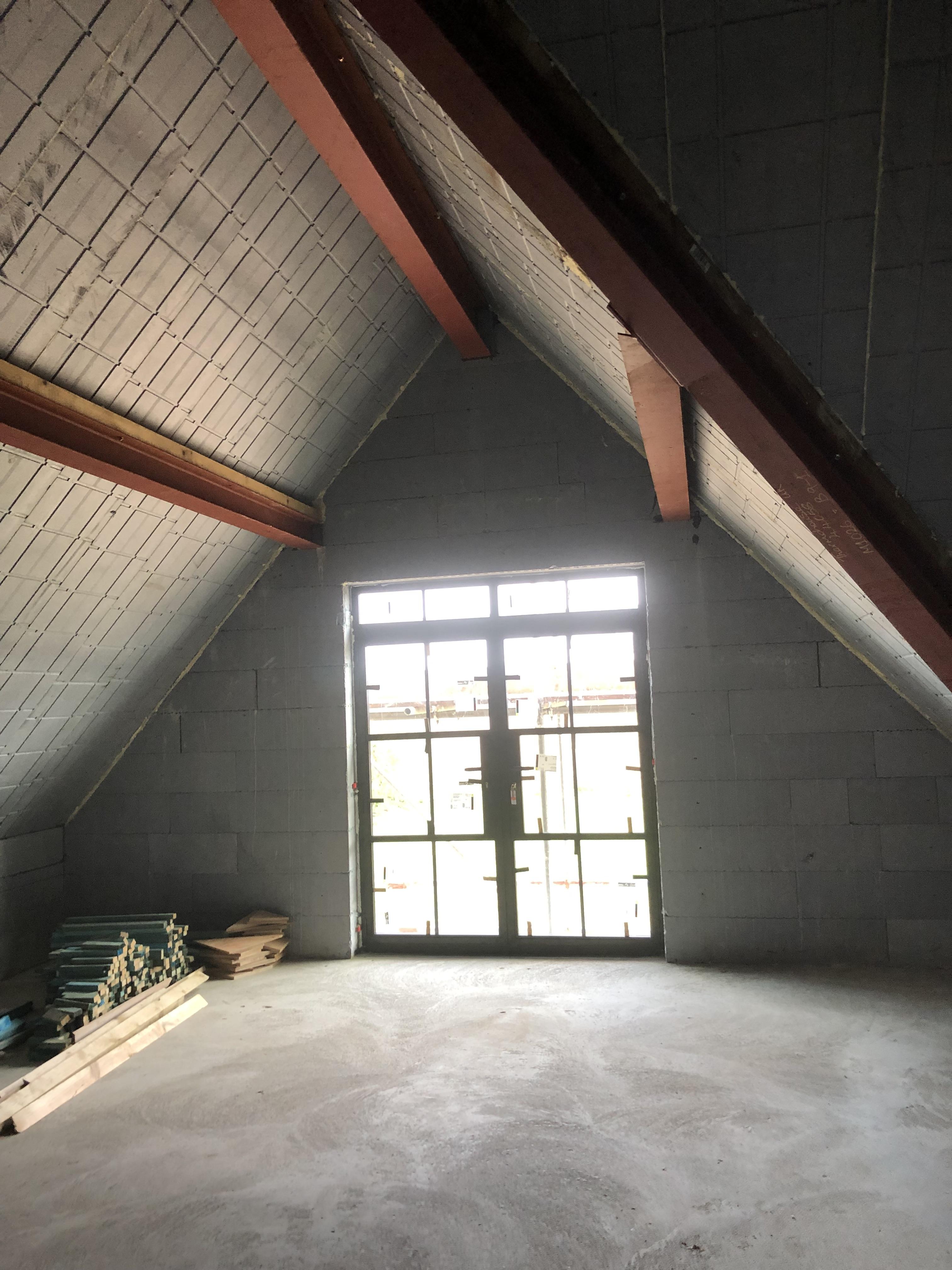
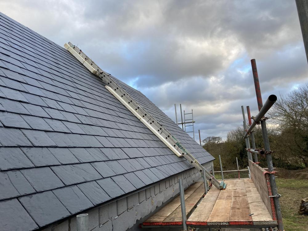
Hello @SuperJohnG, what did you end up doing? My Thermohouse roof boards, with battens currently make 460mm flat fascia edge. I’m thinking of cutting off some of the EPS up to the embedded metal C section. Don’t really have a good photo of this to hand.
-
When I researched this topic Siga were the only supplier I found with specific details about their tapes adhering to EPS. https://www.siga.swiss/_Resources/Persistent/7/1/8/b/718bf957c04165095ee6f6c18a04a79f58a4363c/SIGA_Substrate_matrix_en.pdf I sure plenty of other tapes will work, but I expect they will also need a primer for EPS.
-
DIY Fitting of used ashp for cooling and heating.
Nick Laslett replied to Simon Brooke's topic in Underfloor Heating
I don’t believe that MCS prevents you from using ASHP cooling in England. @joth discussed this a few times. There appear to be some aspects that make it a little more challenging. -
When I first joined this forum in 2019 and started my research there were a lot of strong arguments for still using gas if you can connect to the mains supply. I believe they plan to phase out gas connections on new builds, but most of the legacy gas powered houses will continue for a long time. ASHP are good for domestic heating, but have some limitations for domestic hot water, long reheat times and the need for a large UVC. There are lots of old threads about energy costs, but recent events have dramatically changed most of these factors. We ordered our UFH pipes from Wunda and had the ground floor installed as part of the insulated foundation work. We installed the upstairs ourselves. We have a poured concrete first floor. We are not on mains gas, so went with ASHP. One very big advantage of ASHP is that they can be run in reverse and provide cooling, this was the premise behind the upstairs UFH.
-
We got our as-built EPC
Nick Laslett replied to Conor's topic in Energy Efficient & Sustainable Design Concepts
Conor, I’m really sorry to hear that. I am gutted for you. The 2018 Thermohouse house technical manual and construction detail both show that all the roof joints need to be taped for airtightness. Very frustrating that they should give misleading advice and ignore their own manual and NSAI certificate. I am torn with going through the hassle and expense of priming and taping all these joints, or actually having the roof boards internally rendered as our bedrooms are in the roof. I don’t want to appear that I am defending Thermohouse. This is their mistake. For others that find this post here are the relevant details from Thermohouse. 2018 Technical Manual, Page 108, Section 4.2 General Provisions. (Section 4.0 Thermoroof) ”Jointing tape should then be installed over the complete junction to ensure air tightness.” There is a drawing on page 133, Annex 13 – 2. The NSAI certificate for the roofing system has pretty much the same text in section 2.4.4 General provisions. But the drawing shows the tape but doesn’t label it. This is not really detailed enough, and leaves a lot to be desired. I went and got the construction detail from the website, which is from 2010 and not that great, see attached. Finally there is the Fixing Table, document THR-019 also on the website, also from 2010 which indicates that the airstop tape was supplied with the roof panel. The updated fixing table in the 2018 manual leaves this item off the table. Thermohouse could claim that the improvements in PU foam negate the need for airtightness tape. But at one time they thought it was required as detailed across various documents. THR-009a(Plasterboard)Cross Section.pdf -
Regs for self builders - Which parts did you read?
Nick Laslett replied to giacomo_z's topic in Building Regulations
… -
Sunamp accepting granular power from PV diverter
Nick Laslett replied to willbish's topic in Energy Storage
@willbish, do you have a Myenergi Eddie solar diverter connected to your Sunamp? -
MF across sloping ceiling
Nick Laslett replied to crispy_wafer's topic in General Self Build & DIY Discussion
Thanks, Nod. I should have mentioned I’m using the Thermoroof boards. So the fixing is buried in 80mm eps. I need to make a lot of dwarf walls to close off the space.