Nick Laslett
-
Posts
687 -
Joined
-
Last visited
-
Days Won
1
Everything posted by Nick Laslett
-
Just getting back to some plumbing tasks. I have always liked this thread’s discussion about hot & cold design because it was so clear. Re-reading, I picked up on the point about “cold mains priority”, which I’ve not seen mentioned much in other threads. This led to @Jenni adding the Control group box to her schematic. A quick google led me to this very fancy looking valve. My question was do I need one of these to give my Sunamp cold mains priority? @DamonHD, @ToughButterCup, @Russdl do you guys have any thoughts on this question based on your installs? Midsummer Energy have this kind of valve as part of the Sunamp page, but the actual Sunamp manual is suitably vague. https://midsummerwholesale.co.uk/buy/sunamp-heat-batteries

-
The decline in sentiment on this forum would appear to be due to initial equipment cost outlay, and cost and hassle of repairs. A UVC with ASHP will be cheaper to buy and maintain. The Sunamp only has a size advantage compared to UVC.
-
The iCF blocks from Thermohouse used on my build are made from graphite eps beads. They have bolded in the electrical section of their installation manual the following. This short document https://electriciancourses4u.co.uk/useful-resources/what-effects-different-types-of-thermal-insulation-have-on-electrical-insulation/ Puts the onus on the insulation manufacturer, to check their products data sheet. Found this 2004 ministry of defence document advising against electrical cable with EPS. https://assets.publishing.service.gov.uk/government/uploads/system/uploads/attachment_data/file/33549/spec34.pdf I pretty confident that 18th edition electrical regs will be consistent with these requirements. I believe BASF invented the graphite eps beads. They may have some details on this issue.
-
You might already have what you need. Anyway, just popped on the All4 app. Grand Designs: The Streets series 1, episode 1, timestamp 34m:48s This is also the episode with the Thermohouse EPS roof boards, which I have used.
-
Here is a video from Roger Bisby at Skillbuilder about cavity wall insulation. He plays with a straight bat in my experience. I know nothing about the topic of cavity wall insulation, but he talks favourably about most methods of insulating a cavity. He does highlight the need to have adequate ventilation if you improve the airtightness of your walls to let moist air escape the thermal envelope.
-
Insulated Raft KORE - External Protection
Nick Laslett replied to Renegade105's topic in Foundations
You should have the construction details from Kore. They give number of options for finishing the permitter. There are a couple of threads here on this topic. I went with an acrylic render solution, which is discussed here. There are a few posts with photos. We did not need a radon barrier. DPM was on top of the insulation. I don't think you need to seal the EPS. It is better if it can breath and release any moisture. But you do need to deter animals from trying to nest it it.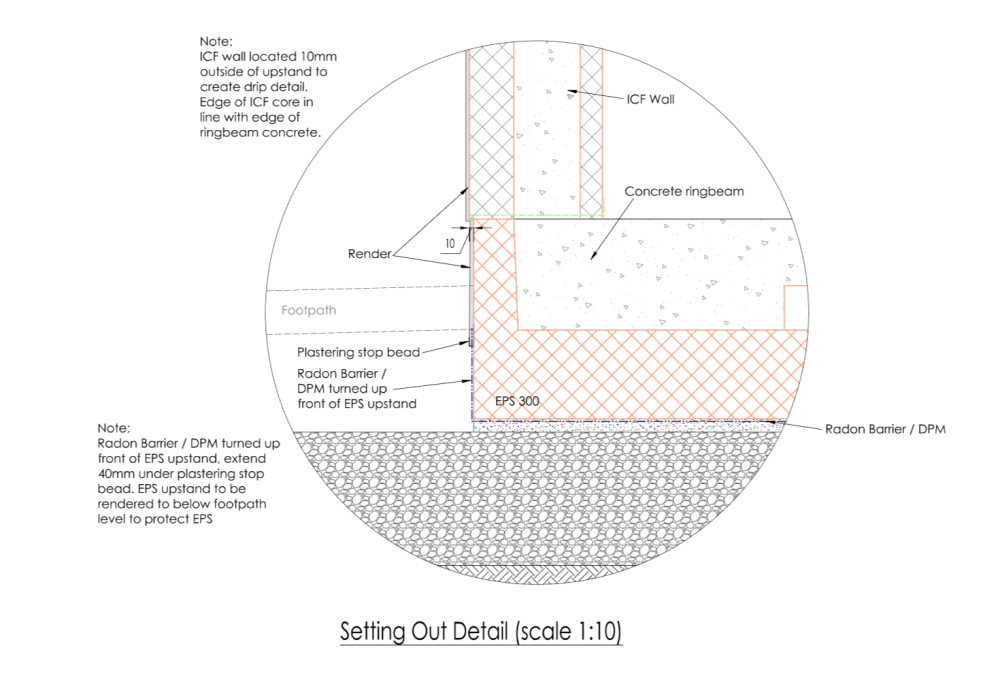
-
How did people finish off their plant rooms? Flooring, walls etc. I have 2x ICF walls and 2x stud walls. Did you plaster the walls? Plywood instead of plasterboard? I haven’t installed the UVC or MVHR yet. Bare concrete slab right now.
-
Do you have a link for the product you used? Is it the https://www.steelroofsheets.co.uk/products/over-window-drip/ from your earlier post?
-
Me too! I hope once the build is finished that it delivers on some of the promises. For me I’m enjoying the self build journey, but it is a real leap of faith. MVHR, ASHP, PV, airtightness tape! This is a huge spend. HeatGeek video on zones HeatGeek video on heating schedules
-
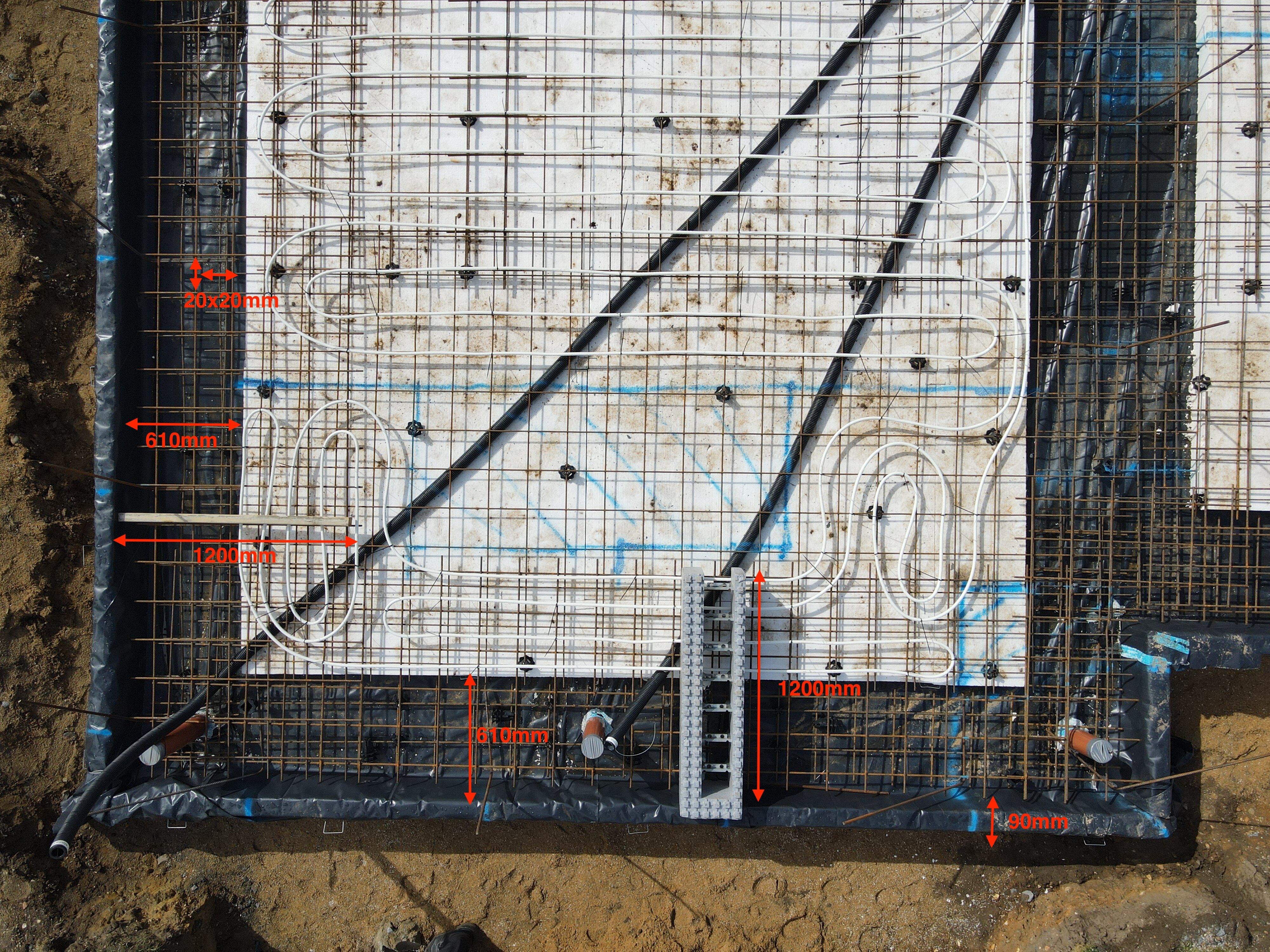
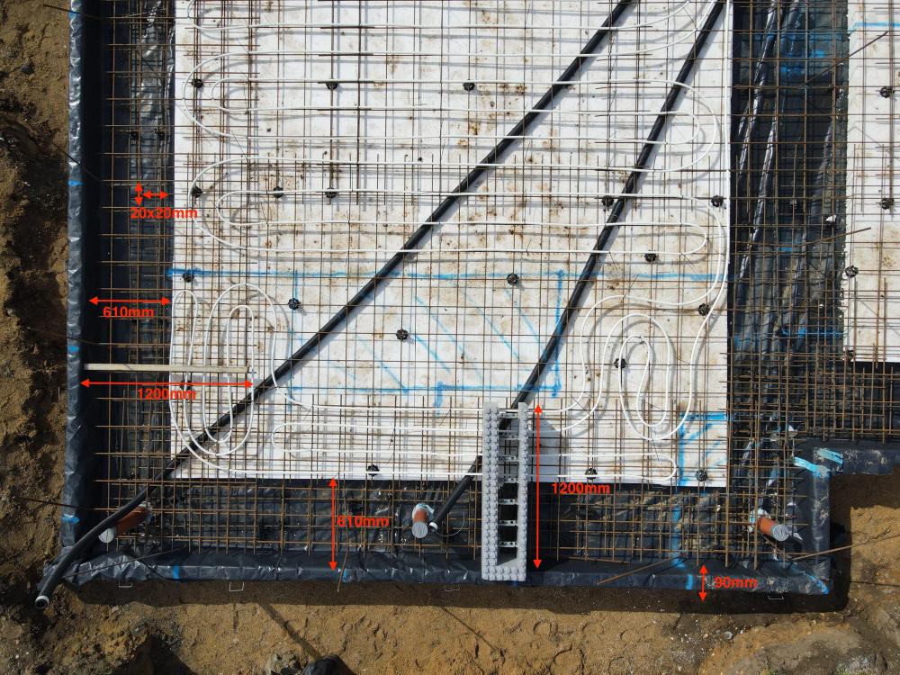
This is a good question. I think in places we did have 3 sheets of mesh overlap. The ducting for the hot water pipes actually created the highest points for the mesh. We have a 150mm thick slab, the mesh is sitting at 50mm, 16mm of UFH on top of the mesh. I measured the highest point, where there was mesh, UFH and duct. This was 110mm, leaving only 40mm of clearance. Most of the foundation the height of mesh and UFH was 85mm. Is this enough clearance? Probably not.
-
I was inspired by @jack to go for the same design in principle, 1 zone for downstairs, Panasonic ASHP, no buffer tank due to quantity of water in pipes. Unlike Jack, none of this is commission, still in 1st fix. So I can’t vouch for the folly of this approach!!! My understanding was with a well insulated, high level of airtightness house, with MVHR, heated by ASHP with UFC, is that having different zones has no benefit to energy usage. All the heat is contained in one envelope, and the MVHR will balance the temp across the rooms. The heat in the UFH is soaked up across the entire concrete slab during the heating season. The ASHP is running continuously, using its inbuilt weather compensation and night time set back temp. I think my target water temp is 28c, for a room temp of 22c, according to the LoopCAD output.
-
@JackofAll, that is a great find. I knew from TDS Ltd’s drawings for the Kore foundation, that he wanted the UFH stapled to the EPS. It would have also helped with ICF wall prop fixings having the pipes deeper. I had my foundation installed by a Kore recommended installer. They do the insulated foundations for MBC Timber Frame. Their preference was to cable tie the UFH to the top of the mesh, which is what they did. See picture in other thread. Our slab was 150mm thick. We also have a 100mm poured concrete 1st floor. We fixed the UFH to the EPS, under the reinforcing mesh. Big fan of LoopCAD. Lots of video tutorials. Also gives heat loss calculations, very detailed.
-
I just ran ducts for the hot water pipes in the raft. This was standard 50mm twin walled ducting. https://www.builderdepot.co.uk/cable-ducting-twin-wall-black-per-metre-50mm The ducts ran under the rebar mesh. The plastic mesh supports were 50mm high.
-
Hello @Russell griffiths, I’m just getting to this stage with the water softener. Did you use softened water with your ASHP?
-
Softened water connected to the heating circuit.
Nick Laslett replied to Question's topic in Central Heating (Radiators)
Does this apply to ASHP? Should it be filled with mains water using the bypass, or can it be on the soft water circuit? The Harvey’s note is about boilers. Existing thread here, but not conclusive. Just did a quick search and came across this advice. https://www.sjwatersofteners.co.uk/is-it-safe-and-beneficial-to-use-soft-water-in-my-boiler/ This is specifically for boilers and clarifies between hot water side (soft okay) and central heating side (hard). Not sure how this applies to ASHP, as my simple understanding is that they only have a heating side. -
Guttering Design - open gutter end or downpipe?
Nick Laslett replied to Nick Laslett's topic in Rainwater, Guttering & SuDS
@Redoctober thanks. Hard to tell in the photo, but it looks like the dormer window gutters are emptying into the lead valley. Is that the correct? -
Guttering Design - open gutter end or downpipe?
Nick Laslett replied to Nick Laslett's topic in Rainwater, Guttering & SuDS
Yes, like this, but not full lead. Thank you. -
Guttering Design - open gutter end or downpipe?
Nick Laslett replied to Nick Laslett's topic in Rainwater, Guttering & SuDS
Sorry, I mean a gabled dormer window. I’ve not got a photo handy. It is higher up on the roof than the picture.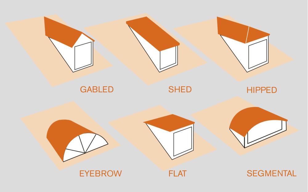
-
Guttering Design - open gutter end or downpipe?
Nick Laslett replied to Nick Laslett's topic in Rainwater, Guttering & SuDS
Thank you, Peter. The photo is fine. Would you do the same with a pitched dormer? Looking around there seems to be no consistency how these are treated. -
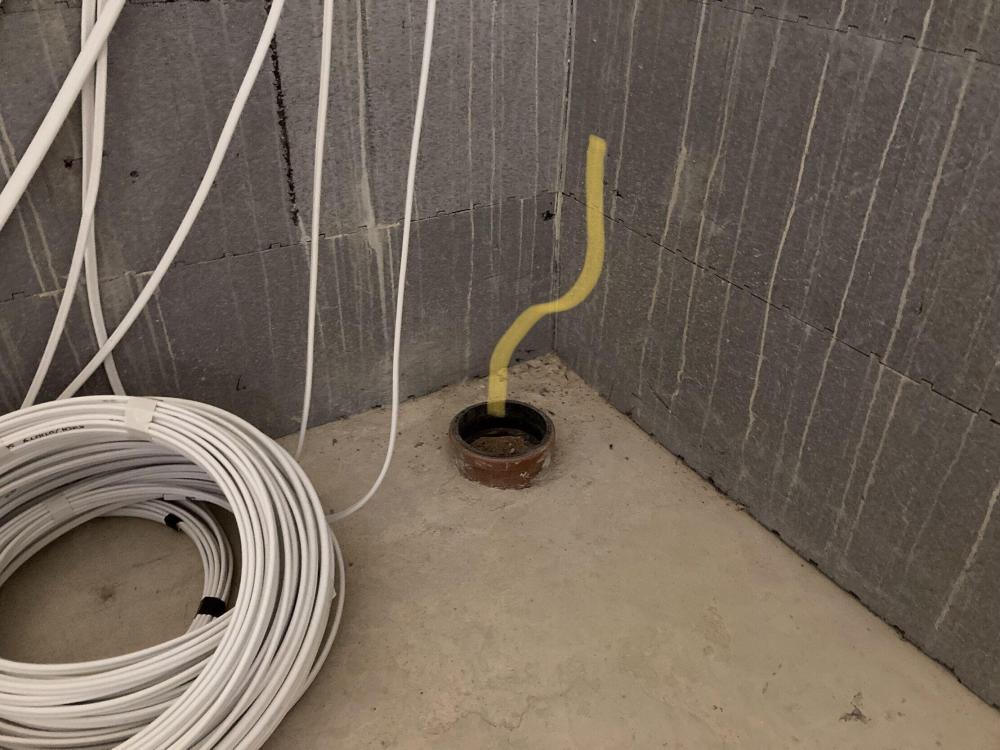
Yes of course that makes sense. This is a stack. I’m not sure exactly how much off the ceiling hole is with the SVP stub in the floor. But between a pair of 22° bends, and some widening of the hole, I’m sure I can make it work.
-
Peter, thank you for the advice. I will use 2 shallower angles and get the stack a little closer. I think it is about 150mm from the wall right now. I hadn’t considered how the fixing might affect this. I will take a look at your suggestions. I have a hole in the concrete ceiling above where the pipe needs to get to. Very hard to make the hole in the ceiling any larger because it is 100mm thick concrete with steel mesh. Is it a problem putting the stack at a 10° angle instead? The ceiling is 2.7m above the floor, so I can easily angle the stack.
-
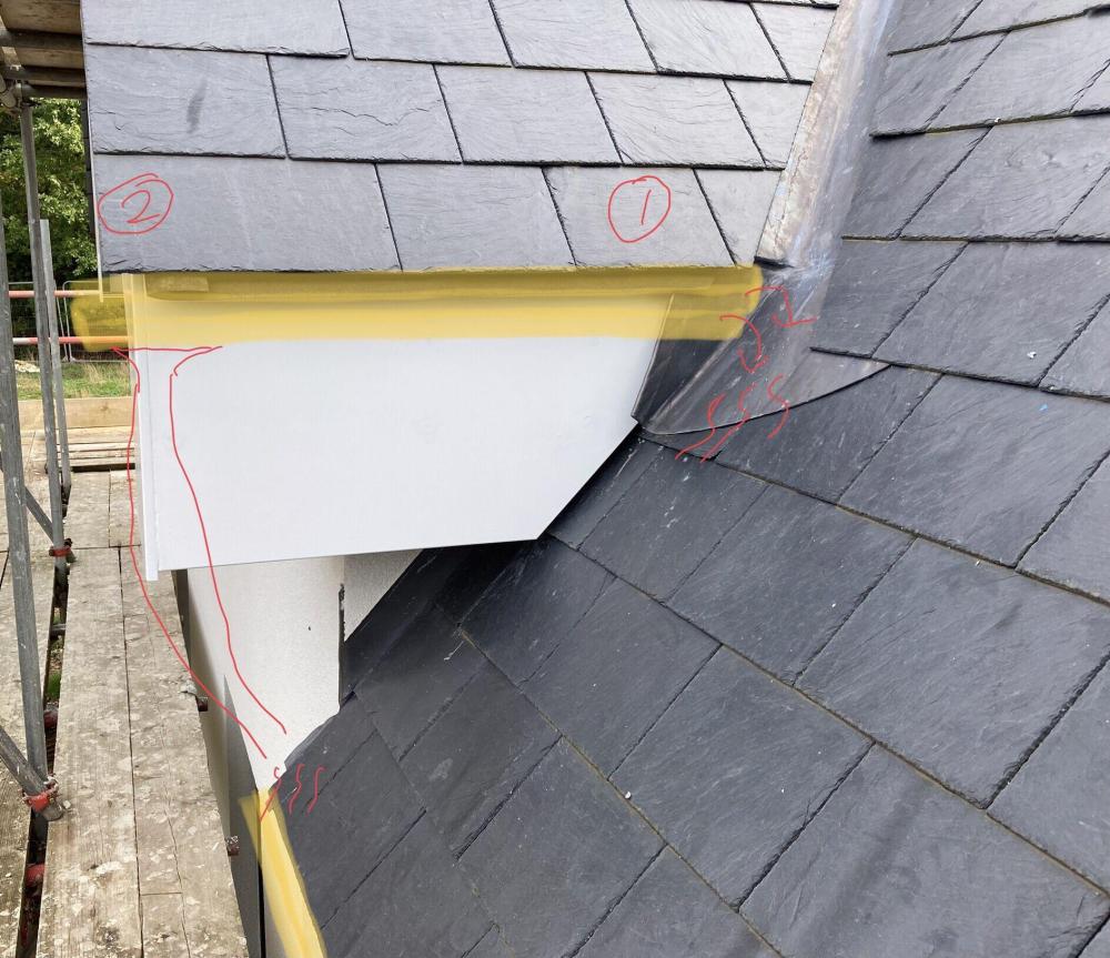
I have 2 short sections of roof where I’m not sure if I even need a gutter. See photo, yellow lines are the gutters, red lines my solutions. My first thought is to let the water run out of an open ended gutter onto the lead valley. Number 1 on drawings. Or put a downpipe to take the water to the gutter on the roof below. Number 2 on the drawing. Or no gutter at all, as 90% of the roof falls onto the roof below. Any thoughts appreciated.
-
I have a few of my vent stacks that need to be closer to the corner of the walls. I assume I use 2x45° To achieve this.
-
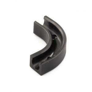
JG Speedfit do a 90° for 10mm. https://www.bes.co.uk/10-mm-jg-speedfit-flow-bend-tube-clip-jg-speedfit-push-fit1-11634/
-
Ground floor Nudura buildup and pour
Nick Laslett commented on BotusBuild's blog entry in South East Cornwall Low Energy build
*copied from an earlier post. We have now passed this phase of our build, the ground floor walls pour has been completed. In the end the UFH pipes were cable tied to the top of the reinforcement mesh in the middle of the raft. The raft was 150mm thick, the top of the UFH pipe in most places was at 80mm, with 70mm of clearance from the top surface. In some areas where there was 50mm ducting for water pipe runs, the reinforcement mesh was lifted and the UFH pipes were at 110mm with only 40mm of clearance. The wall props were 114cm long, and placed 120cm apart with fixings at 18cm and 1m. For the front fixing the builder used M10x70mm tapcon style bolts, we had no UFH pipe where there were front bolts fixings. For the rear bolt fixings we used M8x50mm tapcons, there was UFH pipe present for all these fixings. We ran an air pressure test during the prop fixing process and none of the UFH pipe work were compromised. The walls were poured with only one very minor incident and the props have now been taken down. Hopefully this helps anyone that is concerned with how ICF wall props work when you have an insulated raft with UFH.