Leaderboard
Popular Content
Showing content with the highest reputation on 01/20/24 in all areas
-
Im afraid you will not convince me that its anything other than a good wheeze to make cash. Appreciate you may think/believe otherwise. Ive seen enough of it to know it doesnt work.2 points
-
Nobodys going to do that for the very obvious reasons that have been discussed before. A goodly chunk of the population cannot afford to "change" away from gas no matter how expensive gas is. So they will simply be very cold or hungry. Or both. Easy to say if you are not one of the affected. Though in the crazy messed up world we live in, i guess, eventually government will pay you to do it. Which i think is the approach i will take. Just wait until they pay for it all. Its the inevitable conclusion of the path we are currently taking. Mind you that might be unachievable as the grant harvesting companies will keep putting up their costs inline with the grant increases.......................2 points
-
There should be no issues with fitting the layer of boards above the rafters. These can be butted together and joints taped. Over these boards there should be a membrane and counter battens parallel with the rafters. Regular horizontal battens go on to of these. This construction is known as a warm roof (not to be confused with a warm loft). It's what I would build if building again but not all builders are familiar with this approach. It is quite a bit of work to fit boards between the rafters but my builder didn't complain and I bet my roof is more complicated.2 points
-
Yes i used the double sided. I may be misunderstanding, but why not put VCL UNDER the battens? Or, actually, why are you using a VCL as you have put a DPC in already. Or are you worried about condensation forming within the floor build up? Seems unlikely and thus overkill?1 point
-
When’s the last time anyone saw a completely sodden canal side wall - I’ll bet my hat that it’s never seen a chemical or electrical DPC. Physics guys - just physics!1 point
-
It has been a cold week, so just after 12:30 on the 15th of January 2024, I started a small, but limited, experiment. This was rather prompted by a comment by @Garald who wanted to insulate at the back of his book shelves, and mentioned our favourite insulation, multifoil. @Gus Potter also has a project that may benefit a thin, easy and cheap to make, insulating panel. I think I also made a comment to @saveasteading about this experiment, but can't remember in what context. Now I have always been dubious of reflective type insulation. Works great at high temperature, especially in a vacuum, it is how the cameras on the James Webb Telescope are kept cool. But we are not Billionaires, so I used hardboard, pine, white emulsion paint, double sided tape, small screws, clingfilm and aluminium foil. Basically I made some small St. Ives picture frames, put them face to face, separating the 24mm air gap with clingfilm in one, and aluminium foil in the other. The total thickness of the test panels is 30mm. Each side of the test material had temperature sensors (DS18B20s) inserted via holes in the frame. These had been calibrated before hand and the analysis is based on the calibrated data. Other sensors where fitted in the room and externally to log ambient temperatures (why being a cold week was so good). The panels were then stuck to my kitchen window with double sided tape. The position of the sensors allows for a combination of temperature differences to be logged, logging was at the minute interval but the analysis was based on 6 minute means. A quick calculation to check the standard error showed that accuracy was a factor of at least 10 below the 0.1°C accuracy of the experiment. The data analysis was based around temperature differences, but for some context, internal and external air temperature is also shown on the charts (right y-axis). A frequency distribution line was also added, this is black line (right y-axis) and is called Ambient ∆T Probability Percentage. The Ambient ∆T is the difference between the inside temperature and outside temperature. This is also used for the 0.1°C temperature bins that create the x-axis. Mean temperature differences between each side of the clingfilm or foil (shiny side towards warmer room) were also calculated and binned according to when they happened with respect to the Ambient ∆T. This method is used as it is more relevant than a time series that can fluctuate during the day, it is the properties of the insulation that is being tested, not the absolute 'comfort' levels. The below chart shows the total test period results. Test period (15/01/2024 12:26 to 19/01/2024 12:42) Always remember that these are temperature differences and not absolute temperatures, except the Internal and External mean temperatures (yellow and green lines) and the probabilities (black line). Those 3 are read from the right hand axis. The Clingfilm is the red dots and the Aluminium Foil is the blue dots. Linear trend lines have been added more for clarity than actual predictions. A can be clearly seen, there is not much difference between the two datasets. The Clingfilm performs better overall with a mean difference of 2.5°C, to the Aluminium Foil's 2.3°C. Above an Ambient ∆T of 19°C the Aluminium foil performed a little better. This is actually saying, the colder it is outside, the Aluminium Foil performed better, which may be important comfort, but overall, there will be greater energy losses than with just using Clingfilm as a separator. It is, purely from a climate change viewpoint, the overall energy reduction that is important. Climate change has caused the mean temperature at my end of Cornwall to average -0.1°C for 4 days. I have lived back here for 20 years and never known such a prolonged cold period. I am now running a second test, using one panel without any separator at all, and the other one fully filled with silica micro balloons. Micro balloons may sound exotic, but they are just filler used in the plastics industry. I don't think the temperature differences are going to be so great next week, which is a shame as the greater the range that can be tested, the better. I can always raise the temperature in the room to compensate, but as I raised it up to 24.5°C a few times, which resulted in only getting a mean of 23.5°C in the room, it will be a bit costly and not very environmental. I shall post up the results of the second test next week, all going well.1 point
-
1 point
-
Liquid water takes 4.18 kJ/kg.K. When it gets to a vaporisation temperature, which is dependant on air pressure and ambient humidity, it take 2257 kJ/kg to change state. Now myself and @Gone West looked into this a while back, and I think a common brick can hold around 8% of it's mass as liquid water. Say a brick has a density of 2000 kg/m³, there could be an additional 160kg of liquid water to heat, and then convert to vapour. Brick takes about 0.8 kJ/kg.K. An ordinary brick has a mass of about 2.8kg, add on 8% water and that is another 0.2 kg. To initially heat by 1 K will take. 0.8 [kJ/kg.Kbrick] x 2.8 [kg] x T [Tfinal - Toriginal] + 4.18 [kJ/kg.Kwater] x 0.2 [kg] x T [Tfinal - Toriginal]. 2.24 [kJ/Kbrick] + 0.836 [kJ/Kwater] = 3.01 kJ/g. At vaporisation point. 0.8 [kJ/kg.Kbrick] x 2.8 [kg] x T [Tfinal - Toriginal] + 2257 [kJ/kg.Kwater] x 0.2 [kg] x T [Tfinal - Toriginal]. 2.24 [kJ/KBrick] + 451 [kJ/Kwater] = 453 kJ/g. A huge difference. Though it does not happen all at once.1 point
-
It’s as much about different materials making up the structure so if there’s no acoustic insulation then adding some will help but it will only help not eliminate it. My build up has 100mm acoustic insulation, 15mm plasterboard everywhere with some double boarding, plastered rather than Ames taping, all joints/spaces sealed. It’s hard to tell yet what the acoustic transmission is like as we don’t have any doors fitted yet. There’s a lot of marketing about dense acoustic wool but there’s evidence that as long as it’s at least 10kg/m3 there’s not much improvement by going ever more dense. Thick plasterboard, double boarding, resilient bars, sealing gaps, etc is what you need to do. Here’s a good thread on the subject.1 point
-
way too late for me I'm afraid! already installed and bedded on a thick bead of CT1 along the grout line. I'm sure it'll be fine🤞1 point
-
We can get -9 here, but I made the decision to add about 10 to 15% anti freeze to the system. Accept I maybe getting an efficiency hit. Mitigation were, need all to coincide together, 1. you need a power cut to coincide with the coldest day, 2. I need to away at the same time, to ensure 4 is implemented 3. we have a battery it needs to be flat, but we always keep 5% in reserve 4. and we have a generator that needs to be connected - it may not start. 5. Also cool down time to the water getting to freeze point will be reasonably long. So you need a long power outage.1 point
-
No. This is a stupid idea. Sorry but it is. Lay them properly and check level with with a straightedge, it’s how it’s been done for years before levelling systems came about.1 point
-
........brain search engine tells me it was rockwool batts between I Joists and lots of Illbruck FM330 and OSB as an airtightness measure.....1 point
-
If one of the spacers is a bit high you will never get the tile level and will have the messy job of removing it from wet adhesive.1 point
-
I think it is the same as manufacturer as mine Krono 12mm, the kitchen I did glue all the joints as I did want it fairly water resistant and it is fine with no issues. The hallway is doing what yours has. You could see if you can move the joints apart on the ends (I can move the whole row of boards and seperate the joints by kicking the top of the board with trainers on) and glue the ends, I have managed to on the bad ones.1 point
-
Agree wholeheartedly about hydraulic separation, it is a sticking plaster for poor system design. I don't like glycol either but IMO it is the least worst option for protecting a big capital asset against catastrophic damage without requiring (a) mains power or (b) a seldom-used cheap mechanical device to work first time when you need it. (Yes I am also thinking of service valves under the sink, and pump isolating valves, usually the spindle seals fail when you operate them in anger, giving you two problems where you had just one to begin with. Had this happen on me over Christmas. Not everyone will keep a spare pump c/w valves in the garage.)1 point
-
Getting a new planning does not revoke the older one. You would be able to choose which one to go with.1 point
-
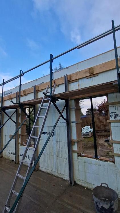
Finally, I added a small piece of 4x1 and a single woodscrew to hold the bolts in place and prevent them pushing out when the concrete went in. The Ledger was levelled and secured with the 6.7mm Timber Screws, but was fairly tightly in place behind the props anyway. The concrete is now in and once it has fully cured, I'll go round and cram the nuts up. As an additional bonus, I think the Ledgers helped keep the wall nice and straight. Hope this helps someone out!1 point
-
Same here 😩. My wife is a life saver listening to me babble on about insane house build problems, that make no sense. The number of times I’ve stopped in mid-rant, when the answers comes to me. The very definition of a sounding board. Anyway @Thorfun, this thread is a goldmine of information, I sure there are many silent readers that have appreciated it.1 point
-
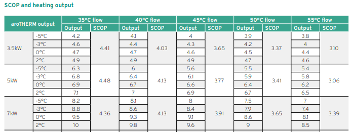
Heat pump sizing is simple enough. you need a heat pump that can deliver your required heat in about 22 hours, this leaves 2 hours for DHW heating. Other other thing to look at is output at your flow temp temperature and lowest outside temperature. This where you need to start looking at different datasheets. Some manufacturers quote the best output figure others the minimum, so headline 7kW doesn't mean the same thing, when comparing products. So you looking for around 8kW output at say -3 to -5 A 10kW Grant heat pump at -7, has a rated output of 8.1kW. So is fine, the next size down is 6kW and is too small. A 7kW Vaillant for example is fine until flow temp required at -5 goes above 45, at 50 it will struggle and outside temperatures below -5 would struggle also.1 point
-
MVHR units themselves leak, we had a similar issue, we blocked the inside room terminals, but I could feel the air leaking into the room where the MVHR units are located during air test. Our final air test was no better than our pretest and all leaks during that test were fixed. If you are not passivhaus certified, the air test is just a piece of paper to keep building control happy.1 point
-
Lets hope im dead by then...................0 points
-
0 points
-
It's a Fools Errand. Thats why on this a particular task SWMBO is sent - so that when she returns, scorched by the heat of her own worthiness ( and having spent a King's ransom on [... unnecessary sh!te .... ] , I can get my own back saying ". Ah, mmmmm, that won't work ... I'd have thought that was obvious ... dwahling .... " And try not to sneer while saying it. Even's up the score a bit0 points


