


Gus Potter
-
Posts
2383 -
Joined
-
Last visited
-
Days Won
34
Everything posted by Gus Potter
-
There was a whole page on swimming pools that cropped up. Not a big issue up here in Jockland as it's wet enough already. Have a good PI broker that understands the construction industry so can discuss risk and what I'm up to. Yes but you hit the wall when less than 1.0m from a boundary both under the English and Scottish regs. Strangely fires in Scotland are suggested to be hotter than English / Welsh / NI? fires once you really devle down into it, but at that level much is open to intrepretation and the wording of the regs. I'm curious as to the 40% value. Is that something to do with the regs or a rule of thumb when trying to get off the shelf insurance, NHBC type support if you are a volume house builder? I don't think they do as it's not a mass market. Hopefully things will settle down and lenders will appreciate that there are "new" proven ways of constructing houses and that there is money to be made by writing policies that cover what we are discussing.
-
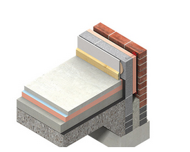
Hiya. If the floor screed touches the outside wall you get a cold bridge. What you do is stop the screed often 25 to 50mm from the wall and put a bit of insulation that is vertical. Like below from screen shot of Kingspan detail To finish the existing house walls I always want to know if the existing wall has a clear cavity or if it is fully filled with insulation. If not fully filled then you often get a cold draft in the cavity so the existing wall is cold. Plastering this is not my preference as it can attract condensation at the bottom / top if a kitchen area. My first choice is to strap and line with 40mm insulated plasterboard. Yes it thickens the wall a bit but you can lose quite a lot of heat on a windy winters day due to a drafty cavity! I would look to see if you can tape and seal the DPM as best you can, avoid raggling (grinding a groove) out the block to rebate in the plastic.. not a good structural option over that length of wall. Try and lap a bit of DPM up the wall, tape and seal and take it above the top of the screed. The vertical insulation (perimeter insulation) is often water proof anyway so you have belt and braces.
-
OSB on some internal studwalls?
Gus Potter replied to ashthekid's topic in General Structural Issues
There are lots of reasons for doing this even if not absolutely speced by SE. Yes the adding a bit of OSB to the wall adds robustness to the building. Take photos if you do as if you make alterations later then you may win a watch. Make sure you use the right nails. Say 3.1 x 50/65mm long improved of galv nails at 150mm ctrs around the perimeter and 300mm internally, standard TF spec. On a day to day basis great if you want to have something to say fix like shelves. Acoustically you may be better with two layers of plaster board, but it will help a bit. Again in TF design we sometimes are allowed to take account of the stiffening effect of plasterborad, ok but I'm not that keen say near bathrooms as it gets wet. The main thing is if you want to add stiffness from the plasterboard is to close up the screw centres, use screws not nails as you can get better control over the fixing indentation in my view. In any event always worth improving a buildings robustness. Just one last thing.. if doing so in a corridor or up a stair say make sure you don't accidentally make it too narrow and breach the building regs by 11.0 mm! -
I think Charlie has a point to make in the context of the current climate about obtaining insurance for self build.. at a reasonable rate. Charlie.. my interpretation.. please forgive if wrong. After Grenfell, we have not made any material progress in terms of updating the regs to date. When last renewing my PI there were about an extra five or six pages that asked in great detail about what I have been doing in the past and what I will be doing in the future, and even what I may be thinking about in terms of cladding and fire design. I almost expected that the last question would be on my preference now or intended of underware.. boxers or something more.. modern, body sculpting but flammable. Clearly the insurance companies are evaluating their risk model. Charlie that said I hope that you will agree that we can often design a TF with significant areas of say timber cladding that can comply with the regs even if it is more challenging to obtain insurance in this current climate. Once you get close to the boundary of a site timber cladding often just does not fly as an external covering, but in general can we live in hope?
-
Delighted for you, great part of the country. I'm not far away from you. As others have said planning is to do with what it looks like from the outside not what is behind the facade. However the planners may be quite interested in what you are doing as they will may want to learn from what you are doing for experience. BC will also I think be interested for the same reasons, when you get to that stage. My advice is to engage and embrace.. you may get a pleasant surprise, if not you can battle away after. In terms of the ground you may find... mostly over consolidated boulder clays, good ground. Occasionally if close to the coast then you may have what are called raised marine beds, these are sands and gravels that were left behind when the sea leavels were higher after the glaciers melted.. look up last Loch Lomond ice age etc. Now you also may have a bit of mining. Follow link below for a play about. https://mapapps2.bgs.ac.uk/coalauthority/home.html Your Cruck frame. Spot on. Don't know how much you know about these but even if you know a bit go back and look at first principles and how they work. The key parts are the cruck blade, collar beam and arch brace. They are essentialy how a modern portal braced frame is assembled. Have a look here at a knee braced cold formed steel frame.. see the similarity? https://www.capitalsteelbuildings.co.uk/gallery-agricultural/ If you can get a handle on how the main frame works then you are up and running. The other parts of the frame are there to add extra stiffness to the main members and act as a carrier for your roof and bales. The main thing for me to say.. hey the roof is permenant, provides lateral stiffness against wind loading parallel to the ridge and we need some other logitudinal bracing in the direction of the ridge within the walls. Try and put all this on the warm side of the insulation envelope. Then introduce the bales.. really they are just like rendered wool / wattle / carrier boards. The main thing is if you get it wrong with the bales you don't lose your shirt while getting something that will last many generations. Not sure how far on you are but what info do you have at the moment? Don't rush to trial pitting before you have got all the other stuff in place, no point in just digging randomly before you have got the planning sorted and the footprint established. You may accidentally dig a pit right under a frame base, soften the ground and cause yourself a problem. Sometime pits can be targeted so you can also use them to gather info on soakaways etc.. get more bang for your buck. All the best and keep us posted.
-
Well @PeterW @CharlieKLP You have opened a can of worms here! I think Charlie is right to some extent that you may find it harder to get a range of offers on a self build loan if you have what the insurance companies deem to be a bit off piste, not enough info on the risk. Disagree with Charlie here, it's a relaxed forum and sometimes we just choose the wrong form of language.. I often do. @Selfbuildnewbie To help you on the way. A timber framed house is just that. The internal timber frame carries all the loads, from the sideways wind and the floors and so from above. This is the skeleton of the house. Attached to this can be, facing bricks / blocks / timber cladding / cement based boards that are finished with something, could be paint even or thin texture material. It's not quite that straight forward from an SE point of view as the outside skin can also stiffen the TF so the outer skin does have some interaction with the TF..long story. Now wood burns, thus if a fire starts on the inside of the house you need to stop the timber frame from catching light from the inside for a period of time. On the outside you have to clad the frame with something that will not do these things: 1/ To not become alight if say a window breaks, sparks / flames fly out and set light to the outside of the cladding. This is called often surface spread of flame. Thus you can't have on outer skin crepe paper, to be extreme. 2/ That if you get visited by vandals it's not easy for them to set your house on fire.. again surface spread of flame. 3/ That the outer skin of your house will not heat up too much / or fail and send sparks over a boundary. Long story but this is called a fire boundary condition. If the wall heats up it will radiate heat like an electric fire. Sparks are self explanatory. 4/ That you protect the timber frame skeleton so that it stays up long enough and not fall down as it is holding all the other components attached to it that are doing their thing. Funnily you don't have to protect your detached house from a neighbour's fire under the fire boundary regs. However I always like to think about how you protect folk from the daft things their neighbour may do. @Selfbuildnewbie don't be disheartened.. it's a big challenge to self build but you are going about it the right way. So much info to process... it will all come together in the end though.
-
OT sorry.. It's a bit of a scunner really that the insurance companies have these quirks. It's perfectly doable to design a fire resistance low rise TF house structurally that is also fire safe. It's a huge topic but the main principles are: 1/ You need to design so that in the event of a fire the occupants are warned of an outbreak, that they can exit quickly and safely. Should they not be able to do so then they are protected from the effects of smoke and heat for a length of time sufficient for the fire service to effect a rescue. 2/ That the fire service are not endangered by an unexpected / disproportionate / rapid collapse of a structure. 3/ That you don't set light to neighbouring properties. In most cases I think the biggest and most common bill the insurance companies need to swallow is that from water damage caused caused by the fire services on low rise housing. Hopefully things will change in the future as insurance companies revisit their risk exposure. Yes the dormer cheeks are part of the roof so often considered as a non structural element.
-
Bit of SE input here just to complicate matters! When the wind blows it endevours to collapse your house like a pack of cards. To provide a bit of context. Even in benign parts of the UK you are designing for a magnitude of 200 -250 kg of force for every square meter of upwind elevation exposed to the wind. You can quickly see that the sideways load is quite a lot, given that say a family car may weigh some 800kg? Also the roof.. it is quite a big house and the roof acts like a sail on a boat.. more force. Some of this sideways load is resisted by the outside walls but when you put big openings in them they don't work so well. Thus to offset this you want a good few walls internal walls on the ground floor in both front to rear and gable to gable directions. Ideally you want walls that are longer than they are tall both internally and externally. This is a good way of grasping what will be an economic structural concept. At first glance your ground floor layout looks like you will need to spend a bit more on the structure, possibly more than you want. The pocket doors are shown within the thickness of a standard wall.. tricky. If you look at how much wall you have left that is available to turn into a structural wall then you don't have much to play with particularly in the gable to gable direction. You can still have pocket doors but often you need to thicken the wall so that one part of it still remains a structural wall that can carry both vertical loads from the floors above and resist the wind loads. You have some pretty big spans there on the ground floor and a fair number of things above to hold up so bearing this in mind.. I would ditch the pocket doors from an SE point of view. Also in service.. having pocket doors from say living room to a music / tv room does not stack up due to sound transmission. It's great the open plan idea but they can be noisy. It's time to put some gridlines on these drawings at the concept stage so you can see how things line up properly. You could easily loose thousands here by needing extra structural works that are not required!
-
@JohnMo That does look good I think, once it's planted up and weathered a bit..better still. Does not look like you are retaining the full 2.0m height on the high side though so probably not that much load on it. Could be a haven for insects and solitary bees especially in the winter as the soil at the back keeps things a bit warmer.
-
Good point.. but remember that you could be weakening the existing house wall in terms of horizontal stability if you cut it. I would check with the designer before you do this. @jimal1969 where the new wall interfaces with the existing rear wall looks like it is in a pretty sheltered spot so less risk of driving rain causing a damp problem. I would try all other options before cutting the existing brick first. I would imagine that you are going to strap the existing rear elevation wall and line with insulated plasterboard anyway so the any occasional increase in mosture is not going to pose much risk. If you are just going to plaster onto the existing brick then.. could be an issue for condensation and so on. In terms of you DPM. Are putting solid insulation on the slab with screed or some kind of floating floor? You usually need some perimeter insulation vertically so should be able to cobble up something with tapes and some extra DPM / DPC to protect everything from the masonry below DPC level. Anyway you are now into spring.. good building weather.. what more could you ask.
-
Good question about restraint. These brackets are good but does this seem possible? Build the 100mm block off the 140 block. Each side put full depth noggings (dwangs) hard against the 100 mm block within the depth of the floor joists. The noggings will also serve to support the chipboard flooring edge and the noggings are then tied into the first floor diaphragm. Even what you have is recognised as an effective lateral restraint so the noggings will really do the business. The 140mm block, although a pier looks suspect at first glance, will carry a lot of load as the joists above are loading the wall almost about its centre of gravity (photo 2). As the joists above are continuous the wall will attract more load, which acutally helps in a lot of cases to improve its resistance to lateral load.
- 1 reply
-
- 1
-

-
Revised timber frame details with stone cill
Gus Potter replied to maxdavie's topic in New House & Self Build Design
That's the great thing about BH that I appreciate. Henry Ford et al the car maker alluded to this. Best way to learn is from others mistakes and not repeat in the hope that it will be ok on the day. For me the details look expensive to build, hard to supervise and even if doing it all yourself when you get to the door openings the forming of this it will be really difficult, time consuming, frustrating and at the end of the day you may cut corners. In this current climate it's not easy to buy anything that is not bog standard. I would have a serious think about how this complex detail is going to cost you. Think about a trade off. Maybe accept that in the round the base detail may not be perfect in terms of energy loss in isolation. Make a saving here by going for a standard detail then use this saving to deliver more benfit else where? If you are concerned about the environment in the long term then we should be designing things that will last for 100 years at least and can easily be maintained. We should have a mind to others that come after us.. we have a duty to design such that things can be adapted at reasonable cost for later generations? Ask yourself what is it you are trying to achieve? -
Screed deflection and microcement curing time
Gus Potter replied to Adsibob's topic in Floor Structures
Interesting topic. before you go for these types of floor finishes please consider this. I hope this is helps a bit. To start from the top, these types of polished floors are expensive and you don't want them to fail. If you have a beam and block floor say the following is not applicable. If you have a ground bearing slab, maybe the UFH is in this slab. Under this could be insulation, or it could be on top but all generally rests on a bit of hard core on virgin ground. Now if the ground is a sand then this tends not to shrink settle so much, but if clay it will shrink and settle by different amounts, often more than a sand type soil. Clays shrink when they lose moisture. Thus when you put a roof / building over clay the moisture content will drop. Sand is less effected. But there is more so you are not off the hook yet. You builder or you may put down a layer of hard core and compact it well but the soil underneath will still move about, it is not your builders fault. For the avoidance of doubt you often see specified for a ground bearing slab that is not carrying other loads "anti crack" reinforcement.. could be say an A142 or A193, sometimes A252 mesh. This description "anti crack" is acually a misnomer for the unwary. All concrete cracks and during the curing and hardening process the forces generated in the concrete are quite large. Steel is quite stretchy! Actually in the modern design codes we talk about "crack limitation" , "crack control" They recognise that your structural slab is going to crack and that you design to limit the crack size to what is acceptable. Now if you are designing a nuclear waste storage facility you want to make the cracks as small as possible, and if you are putting a polished concrete type screed over the top you need to take the same approach. Thus you often need to spend some extra money early on and design all the stuff underneath for your fancy / expensive floor finish. Next when you pour a screed or slab you get an effect what is called curling in the concrete @saveasteading has some stuff on this. I experimented on my own house to see if this was just applicable to big stuff or not.. turns out that even for my DIY (even on a 3.5 x 3.0m slab) job the theory is correct. What happens is that during the curing / drying process the top of the slab shrinks more than the bottom and this causes it to bend up, particularly the corners. I went round with a bit of wood tapping the floor and it was solid in the middle and sounded hollow at the corners. Now I know if I add a bit too much load to the floor at the corners it will crack until the mesh takes up the load. I'm not fussed as I have a wooden floating floor so if the concrete does crack we won't see it. So the key things for me are that if you are intending to have polished concrete floors / fancy finishes then you need to spend the money on designing from the virgin soil up. The companies that provide these floor finishes know this and I have touched on the ins and outs.. you have little chance to if any to make any claim against them unless you have a grasp on the design from the virgin soil up. In summary, you can't polish a jobby. You can take the risk of having a cheep standard slab and steel mesh say A142 under and have confidence that you can gold plate it with polished concrete.. but much will depend on how much shine you can apply.. all shine wares off eventually. -
Have seen plenty Schuco stuff on commercial projects. Robust system, but the profiles can be bulky at times.. lots of frame, less glass. Express Bifolds.. same and the handles / locking / escutcheons they offer may not suit everyone. Have a look at the Origin system. I have theirs, not without fault but generally a happy customer.
-
Very clever! hat off to @saveasteading its almost counter intuitive to use a smaller diameter pipe. Yes I too think you could make this fly with careful control over the laying of the pipe and the odd extra inspection chamber. On a straight run its even more promising.
-
Hope all well at your end George. The thermal mass thing seems to out of favour on BH at the moment. But yes I think you are hinting at how a Trombe wall works.. and that will play havoc with standard software! Spot on George.
-
How does your garden grow?
Gus Potter replied to recoveringbuilder's topic in Landscaping, Decking & Patios
They look like they are functional but actually not. Each year they paint the sheep a different colour in aid of the cause they are supporting. The thing they miss is that millions of folk drive by each year and think it's some farmer playing with paint but they always look for the sheep, often without thinking. It should have a sign up saying / spelling it out that " the sheep are this colour this year in support of this cause". Past years have been breast cancer, epilepsy, autism. -
What about this bloody monstrosity!
Gus Potter replied to SuperJohnG's topic in Rainwater, Guttering & SuDS
True enough.. but we can't see the whole elevation and the context in which the building sits in the landscape. It may be that the apparent lack of symmetry is intended? -
What about this bloody monstrosity!
Gus Potter replied to SuperJohnG's topic in Rainwater, Guttering & SuDS
Suggest you rough something up for now to get the completion certificate. Finish the rest. Make a list of the things that bug you, prioritise and tackle in order.. or do the first few.. then go on holiday.. plant a blackthorn hedge and make slow gin, get a pig.. and roast it when fat.. or just relax in the knowledge that you did a pretty good job. A land owner once said to me.. don't worry Gus.. you won't see it from a galloping horse. You are a land owner! -
Don't forget Dave Allen. Nod.. your neighbours are miles away.. will you be lonely. On the plus side the soil looks fairly uniform.. good ground?
-
A wayleave question: Underground HV power cable
Gus Potter replied to ProDave's topic in Party Wall & Property Legal Issues
Dave.. it's almost blasphemy but have you checked out the farming forum... you may be already a closet member? They have a lot of good stuff on this, you need to rake about but it is there. They have a good few Scottish members that talk about wayleaves, money etc and the law in Scotland. I know your heart lies with BH. -
What about this bloody monstrosity!
Gus Potter replied to SuperJohnG's topic in Rainwater, Guttering & SuDS
I bet the poor designer is kicking themselves for missing it at maybe even at the planning stage. As a designer you can get really wrapped up in it, deliver a cracking design that really fits all the requirements .. .and to your horror you miss a thing like that.. or worse.. it does not happen often.. but we are all human. -
A wayleave question: Underground HV power cable
Gus Potter replied to ProDave's topic in Party Wall & Property Legal Issues
Dave.. Am I right in concluding that the cable may be routed through your old place? If so then is the reason for holding onto the old place a means of generating income / investment or does it hold sentimental value? Either way often everything has a price. If sentimental, say it was left to you by a relative, then they would have maybe done so in the hope that you would derive maximum benefit from it. It can be reconciled this way? You almost have a responsibilty to make the best of it to pass on / preserve the family wealth for future generations? To start with you may want to discuss with an open mind, make sure you say that everthing is without predudice. Open a friendly dialogue with them, get to know them and the project manager. They may well let things slip about their other options and costs. Use your local knowledge / grapevine. Ask them questions.. safe distances, maintenance zones and so on.. often they open up.. they are not being unprofessional just talking about their job at a technical level.. it will come out in the wash eventually anyway. Best to learn now for free. Having seen the early development of the wind farms in the Borders I would take a leaf out the farmers hand book. You will find very few farmers that go in hard at the beginning. They listen first, nod in friendly way, engage and find out as much as they can for free..they then think it over and absolutely extract the last pound of flesh just at end..or.. they just say NO and get off my farm. -
What about this bloody monstrosity!
Gus Potter replied to SuperJohnG's topic in Rainwater, Guttering & SuDS
If you take the pipe internally there is always the worry that it will block and flood internally. One way of gaining reassurance for rain water is to use say 110m solvent weld pipe inside and through the wall. On the outside do the pipes with your 63mm rain water pipe and introduce an air break so if you get a blockage then the water remains outside. Screen shot below is for boiler condensate pipes but it conveys the idea. Have seen one condensate pipe locally that was connected into the rainwater pipe with no air break or no non return valve. The pipe blocked at the bottom and the water flooded the boiler, exited the boiler and flooded everything else.. consumer unit the lot! @SuperJohnG Looking good. Do what you can in time you have and maybe one day come back to if it really bugs you. Could just be one of these jobs that gets done just before you sell.. one day.. if ever.
-
Quick question to all. Can you still edit your posts, where do I look for the edit up to an hour after posting tool?

