Gus Potter
-
Posts
2383 -
Joined
-
Last visited
-
Days Won
34
Everything posted by Gus Potter
-
Don't try and dry out the clay as it will shrink and probably result in a bad outcome.. the drying effect will continue outwards and could affect the founds. You have a lovely old house, be sympathetic. One aim is to continue to keep the moisure content of the clay as it has been for the last hundred years. In terms of drying time, programme your works so buy as much time as possible. An old rule of thumb is that for things to really settle allow for 25mm thickness a month for a slab to settle down. In other words, give slabs time to bed in, settle a bit, cure properly and develop a few cracks before the final finish. Hard to do but try as best you can to go old school. Post a few details and some photos and folk will give you good advise on BH, maybe save you some money and a bit of grief.
-
Have you tried working from the other end and asking the folk that are doing the superstructure who they recommend and like to work with. By "like to work with" I mean things like how what do the piling folk leave behind in terms of setting out, finish etc.. are they on the end of the phone and so on if there is a query. Have confidence in yourself. Yes it's not a box but you can set stuff like this out ok with the right approach. Ring beams / piles are generally designed assuming the top of the piles are up to 75mm off the intended line. Great interesting ground in Norfolk by the way.. you are lucky. Keep us posted.
-
Great approach Keymon. Just before you embark on this what kind of soil are the base stones of the walls founded on. If clay you don't want to dry it out or it will shrink and cause you big trouble. At the other end if sand then you want keep some "ballast" to keep the sand confined around the founds. They key here is to look hollistically at this and work to conserve / preserve what you have.. but improve using least risk options. Anything you do to alter the conditions of 100 year plus walls and their founds always carries some risk, just think it all through before acting. The "glasscrete" concept is great. To go back in time. We think we have come up with something new but for thousands of years folk have been creating damp proof floors that are breathable. The concept is so simple. You use boulders, single size aggregate that is angular with a low contact surface area and top that off with smaller aggregate and maybe compacted clay. It's (aggregate) shape creates the maximum amount of air voids ( good insulator) while creating a layer that can breathe and so on. Now glasscrete I think is a bit like the stuff you have in a living flame fire, bit more dense / better cemented so it can carry load. 40mm single size granite railway ballast is surprisingly similar? Granite aggregate is for all intents impervious, can't get damp rising through the granite stones. I do wonder just how thick the glasscrete needs to be to achieve the same level of performance as say a layer of PIR insulation. The R value is starting point. That said on BH there are threads about insulating floor slabs and the effect of the perimeter area. See @saveasteadinget al. Glasscrete may have developed this idea where you can heat the soil dumpling in the middle and use perimeter insulation. Now that concept has potential when we come to look at old buildings and how we let them breath but make them warm enough and energy efficient for modern living. Maybe you can extract some calcs / technical data from glass Crete that are applicable to your project? Keep posting, maybe some more info on the walls and founds?
-
Hi Jilly. Have they referenced the clause in the regs. They should have, but if not ask them to ref the clause on which their request for information is based on... as this will "help you" answer their query in a direct manner. Next examine said response and the regs. Is there a reference to say "as far as reasonably practicable" on the point they are focusing on. Post more info on what their actual response / query is. It could be a officer on a fishing expedition so you don't want complicate things by providing extra info that opens other doors you may not wish to open. The as "far as reasonable practicable" is a grey area. If you have time on you side and can't lift the phone to BC (almost impossible these days) then ask them what they would consider to be "as far as reasonably practicable", if it could be sensitive then hold back a bit, but give them some info like you are engaging and let them make the next move.
-
external insulation External insulation on a 500mm+ solid stone wall
Gus Potter replied to Chris HB's topic in Heat Insulation
Hi @Chris HB That sounds great. My Sister lives on Tiree. Questions.. What kind of stone do you have. Is it granite / imported stone from the mainland or local stone off the beach? What are the walls founded on? sand or rock? Wall construction? Have you exposed what is under the roughcast? Is the outer leaf dressed but just weathered hence the render? inner core of random rubble and rough stone on the inside? What is the roof made of, construction and how does it sit on the walls? Lastly don't go hacking off the render before you have fully understood how the walls / their bearing (hesitant to say founds) are constructed and their condition. Post more if you can.. photos would be great and anything else you can think of.- 19 replies
-
- 1
-

-
- solid walls
- stone walls
- (and 3 more)
-
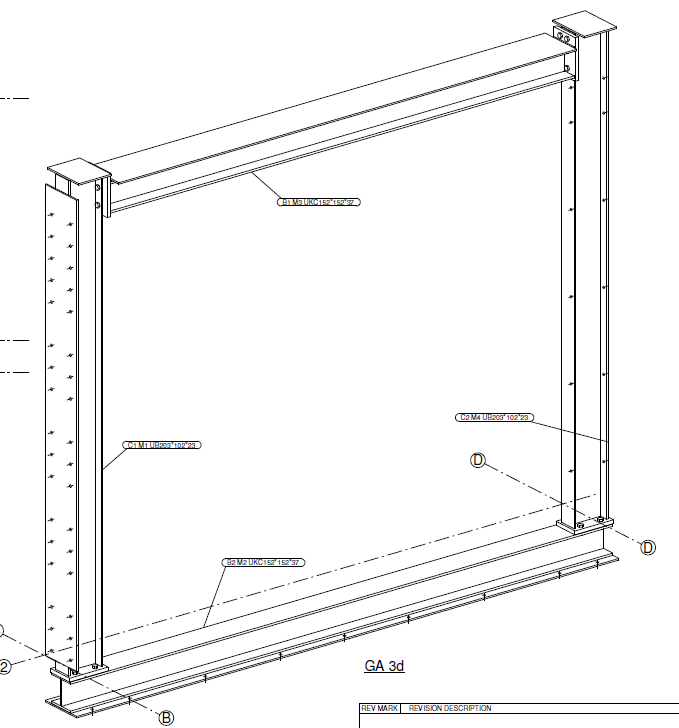
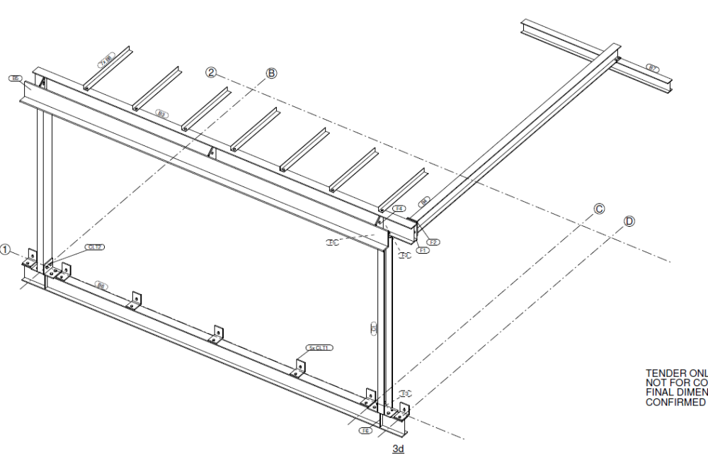
Seems a bit odd at first glance that the outer blockwork support is not designed and detailed. But if the TF company have just designed the TF and the steels directly associated with it they may have put a bit in the fine print that the blockwork lintel over the sliding doors is to be "designed by others". They may have done this to avoid what can be complex to design calculation wise (you need to do part of it by hand rather than being able to use standard SE software, or you can do it all by hand if you have time), time consuming and a challenge wise to detail.. a cost is a attached to this. To explain. After making sure the inner steel (portal in this case) over the doors can carry the loads safely and does not deflect too much to jamb the doors you also need to make sure that the outer leaf intel will also deflect by roughly the same amount give and take. What you don't want to see is a bow in the outer lintel over the doors, no unsightly cracking of the blockwork or of the mastic joints and over stress any wall ties above. Now at 5.0m span things like a sensible cost "L" shape Catnic / Keystone single leaf lintel is ruled out. The next options are.. weld a plate (bottom plate) to the bottom of the inner portal header beam or try to use something like a 200 x 100 x 12 /15 galvanised angle if not too much load above, tight on 5.0m but that is one starting point. There are other ways if the angle does not work out but I'll stick to this solution for now. Go back to the bottom plate idea. What happens here is that the plate acts like a cantilever and introduces a twisting (torsion effect) in the portal header beam. This twisting force needs to be resisted. One way of doing this is to use the floor say above the beam to resist the twisting.. but the floor needs to be right over the beam top flange or very close to it.. then you need to design the top flange connection to the floor diaphragm.. not in the TF manual and it can be hard / sometimes not possible to do.. it's tricky! You'll see in the regs that floors can bear on beams.. simple bearing and be ok but not for beams subject to torsion. You can maybe see that the TF company are thinking the same thing? I'm talking about a pretty stiff connection here.. bespoke. not available off the shelf from say Simpson or Sabrefix. Now if you can't connect header beam to the floor to resist torsion you need to design the header beam to resist the bending / shear and torsion forces. Some SE software packages do torsion design and you can do this by hand if need be using the Blue book with a few extra steps to check torsion. But if you can't rely on the floor the torsion ends up at the beam ends where you have to connect it to the columns. This is where the TF folk probably don't have the time to design a portal frame type connection by hand to also resist torsion as it's a non standard connection and not really covered in the design codes.. which refer often to "Engineering judgement" and "first principles" fine if you have time on you hands but for a TF designer they are working on the clock. What often happens is that you are tight for space to get a 5.0m spanning beam to fit in head room terms at the outset. You want to keep a nice clear square opening for the doors for the fitters and so on.. @Marc can probably fill in on the detail. But when you need to design the portal header beam end connection for torsion you sometimes need to extend the end plate. It can be extended up.. but this can breach the continuity of a TF head binder say, or you can extend the end plate down and put bolts below the bottom line of the underside of the header beam flange.. fitters not happy! In other words you need keep iterating and refining the detail so the structure works and the fitters can do their job. Below is some info showing a couple of way I have done this. The first is from an extension job where I used a single portal frame to support both leaves of the wall with different loadings.. which introduces torsion just as above. This shows a connection that is designed for torsion with the end plate extended upwards. You can equally extend the end plate and bolts down but you then have to check the door detailing and fixing method. This is a box frame that is doing quite a lot of "other things" which is why I have used this for and example.. will expand if there is interest from BH folk. The second detail is where I have used an inner beam with a steel angle on the outside probaly akin to what @Ericneeds. It's not a portal but has other stuff and shows the gusset type connection between the angle and the inner beam. Yes there is a cold bridge but cut me a bit of slack? , the bridge was mitigated in the insulation details. The angle is about 4.4m long and supporting a storey of single skin masonry above. To stop the angle from twisting it's connected back to the inner portal header beam with bolted gussets plates at the ends and in the middle. All these are doing is to stop the angle from twisting and this way you get the best performance out of the angle. There some other what is called "second order" effects happening.. for another day. Again this second detail has a bit more going on.. maybe a bit more interesting? @Eric Hope this helps, post a few more details if you want to follow up.
-
6 bar pressure daytime to my house - do I need a PRV?
Gus Potter replied to Question's topic in General Plumbing
Lucky you! I can see where you are coming from in that 6 bar is 90 PSI. 3 bar ~45 PSI is a good bit of poke but you need flow "delivery" and it needs to be fairly stable. If you have a direct cylinder the pressure relief valve is usually set at 3 bar as are say combie boilers. I wonder what pipe diameter your incoming supply is. Old 3/4 inch or less. If less than 3./4 inch ~ 22 mm) then I would increase the incoming pipe diameter for say 1.0m up to 22mm or more then fit a 22 mm PRV with a double check valve and mains stop cock. The 1.0m before all the gubbins stabalises the flow. After that you can work out the in's and outs. -
My thoughts in line with your text and in italic. So, in summary, the advice would be to - see Actis Hybris's total R results as being inflated, but not grotesquely so Check the fine print. Your starting point here is the European Technical Approval (ETA) Here you should see the test data that complies with the Eurocodes.. pretty much the raw test approval that is signed off. I can see you are putting a good bit of effort into this so hope this helps point you towards what you want to know. - assume one can get as much gain from air layers in the case of BioFib trio as for Actis Hybris An air layer has insulating properties.. yes. If the air layer runs from top to bottom of the the wall then you will get some small convection current within this. But in practice you may have noggings / dwangs and this creates a barrier mid height of the wall. But the main thing is air tightness between the layers. You want to stop convection currents bypassing the insulation. That is where you need tapes if say using PIR insulation.. wool type insulation is more forgiving. The timbers shrink so you can get a gap.. hence air tapes. For starters at early design stage don't place to much (hang your hat) on the air layer. Stick to the basics as later you may need to do a compensatory u value calculation.. if say you have lots of glass. Keep this up your sleeve for now as if you cut it too fine you may have to change the structural design and that won't be fun. - *not* bother to use reflective surfaces on both sides of the air gap for BioFib trio? Or bother (what kind of reflective surface should we use?) and just be realistic about its helping only a little? Again.. keep your powder dry.. cut yourself a bit of slack here as you may have say structural stuff / cold bridging to deal with.. you can always go back to taking advantage of reflectivity later.. An off-the-shelf thickness of 120mm of BioFib Trio gives us an intrinsic R=3.15, which, when taken together with an air layer, would give us R=3.8 (a threshold level in French regulations), assuming the air layer works as for Actis Hybris and assuming also that an air layer helps as much as Actis Hybris's documentation implies.... something that is not necessarily very likely. Of course BioFib Trio is meant to be installed with *two* layers of air, as the diagram above shows. Keep it simple stupid for now, see how the rest of the costs build up overall. Don't try and design too tight for now until you get the whole structure nutted out. Then if you want, go back and refine the insulation once you have have got some prices back.
-
A few thoughts. A few years back on say timber frame the insulation regs changed. We used to use as standard a 95 or 89mm stud, worked fine structurally and still does, the basic generic loadings have not changed significantly. When the regs changed the TF folk were complaining.. we need to go to a 138 of 145 deep stud (before a 89 or 95 stud was the norm) and this will make us less competetive. So they came up with the wheeze on bubble wrap, reflective membranes. I am being harsh but the consequence of this was that the folk on site had to spend a lot more time with attention to detail than before and this comes at a cost. The buck was passed to some extent. Oh.. and if you want to realise the full reflective effect then the surface has to be clean and free of dust and debris.. as per the manufacture's test conditions. I have yet to see a builder who hoovers and wipes down the surfarce of the insulation.. then a brickie that does not cover the lot in dust from the Sthil saw. In reality on a domestic level this is not realised. I see it regularly on the some other sites I visit. I don't on my own sites as I specify stuff and design for what I know can be practically build, what is off the shelf.. sounds boring but this leaves extra cash for the finishes and Architectural flair. It also leaves folk with a warm house as I know I'm not relying on the Builder understanding all of this, even if they do I know they won't really price for it.. they just hope to get away with it. This is good pragmatic design for self builders in my view. If your builder does get the hoover out then you get a bonus. I think the best way is to go back to basics. Look at what you can buy cheeply. Standard off the shelf insulation thickness. What services you need to run in the wall. Get your services runs sorted then check your overall U value. Make sure you can get the fixings you need for the thickness of insulated plaster board. Once you get this basic arrangement sorted go back and check you dew point/ condensation profile for due dillegence. In summary the best advice I can give is to stick to the basics. The big money gets lost in the founds and the risk lies in the ground..spend most time on these aspects and this will allow you to increase the insulation thickness etc and not have to worry too much about quality control on "reflectivity". In terms of detail and workmanship you need to concentrate on the junctions / interfaces.. that is where the moist air will get into your build up. and cause trouble.
-
You are not alone. My practical suggestion is this. The R value is linear and based on an infinite surface area. That is your starting point. You use this to get the U value of your build up. You can get into perimeter effects, try and delve into the manufactures' test data.. but they don't give away the family jewels and the underlying research data. If they do folk will post it on BH and it will get ripped by the likes of @SteamyTeaetc. You have two choices.. 1/ Torture yourself doing calcs, trying to piece together obscure data. 2/ Recognise that that constuction process is pretty rough and go for a thicker / higher performing off the shelf insulation, cover your bases and march on with the build. If in doubt up the thickness, go for standard thickness off the shelf insulation, easy buildable details and that way you can save money for the things you will see on a daily basis. I say this as have been involved in development and research in a commercial environment so will bet you'll struggle to get to the bottom of it. We don't spend loads of money on research and then give away the secrets! One of my jobs was to make sure you publish enough but never enough to let you competitors see in the black box!
-
@George Hi George. Good summary but where folk get confused is when say a beam that on first appearance seems to be carrying only vertical loading suddenly needs a lot more fire protection, often jumping to one hour when you have a boundary condition. The reason is that often it may be providing lateral restraint to another element of the structure that relies on this lateral support to maintain stability during and after (not covered in the regs but good design should consider keeping our emergency services safe) a fire. I posted earlier some extracts from the English regs earlier (not checked the NI regs yet but assume they say the same). Clause 5.2 covers this. The Scottish regs are similar in this respect. The dormer? My starting point would be to ask.. is the dormer part of the roof / rafters? Is it sacrificial like the rest of the pitched part of the roof. I makes no logical sense that you can let the rest of the roof burn away but have to fire protect the dormer cheeks to a more onerous level as the support stucture for the dormer would have burnt away.
-
Agree with you John here about the NEC contract. The Egan report followed up on previous reports. Basically it was and still is costing us more in the UK to build stuff cf some other countries. At least we seem to have rooted out the out/ blatent (some may argue otherwise) corruption in the UK... thinking the Poulson scandel here for example. The NEC suite of contracts forces you to play ball but they are expensive to adminster and not really applicable to small domestic self build / home extension works. To quote myself, bad form.. but to clarify. "this is not as easy to negotiate on larger projects / commercial works. " My intention here was to highlight the amount of effort you need to put in and support systems you need if you go open book say along the lines of NEC contracting. NEC.. it's not for folk on BH. In the current climate basic old school open book type arrangement could work well for folk on BH so long as you do your due dilligence and make sure say your builder is really opening up and declaring all the information. Interested to hear you are working at Hinckley. I was at the Torness build briefly and did some stuff on the Bradwell decomissioning... time flies by!
-
@nod Feel for you Nod. You spend years building up a good business, good reputation for high quality work and something like this happens through no fault of your own. Hopefully pragmatism will prevail and you will reach an equitable agreement. All the best for Monday. For all. A few of the domestic builders I work (extensions and garage conversions for example) with have been doing open book pricing for a while. They have been fixing the labour cost, declaring the material cost and asking that if the materials increase in price the customer makes up the difference, if they drop the sum due for materials is reduced accordingly. Unfortunately this is not as easy to negotiate on larger projects / commercial works.
-
Designing new flat roofs with PV from the start
Gus Potter replied to low_and_there's topic in Photovoltaics (PV)
Not really but others may know more. The thing is that that any advantage gained by way of load reduction when retrofitting PV would be offset by the cost of trying to make a flat roof water tight if the carrier system for the PV needs fixed down to the underlying structure. Any leaks could mean the panels need to be lifted and that could be the start of a nightmare. On a flat roof if the PV panels are to be pitched then the carrier system has some self weight.. which again reduces any benefit of the proposal I make above in terms of justifyable load reduction. -
Is the stud to the far right continuous between the floor and the top rail? If not that is the underlying problem. Was also wondering if that should be detailed as a deflection head type arrangement?
-
Designing new flat roofs with PV from the start
Gus Potter replied to low_and_there's topic in Photovoltaics (PV)
Good point. Often if converting an attic you run into head room problems and you want to try an avoid having to strengthen / deepen rafters if you can. PV panels have become much lighter as time has passed. SE wise you check the roof for the following: 1/ The self weight of the tiles / rafters and so on plus an access load of about 60kg per square metre. 2/ If a low pitched roof.. access plus wind loading.. sometimes critical if a big flat roof 3/ Snow loading plus roof self weight. Now in many parts of the UK the snow loading is much smaller than the access load. And under normal conditions you would not expect folk to be standing/ placing scaffolding etc on your panels (this would be what we call an accidental loading case). Thus you can primarily design for the self weight of the roof plus the panel weight plus snow which could be less than self weight plus access and you may find that works to give you head room inside if you get stuck. You could go further and go for an in system (if you can detail the ventilation ok) where you just have lightweight trays. Load is reduced further (no tile weight etc) and you save a bit on the tiling which offsets the cost of the trays. The difference is small but if you are struggling for head room have a chat with your design team. -
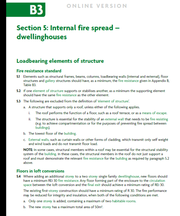
Hope this helps you crystalise your thoughts and good to hear you are using light gauge steel.. always worth considering for attic conversions. For all. A bit of general background info. On a bungalow when converting the attic we consider (not least though) these main elements: 1/ Fire prevention..eg making sure that electrical cable sizes are designed for possible embedment in insulation so they don't over heat, correct installation of say wood burning stove flues and so on. 2/ Fire detection and warning.. smoke / heat alarms. 3/ Means of escape should a fire break out. Sometimes called travel distance or, if you have an internal room how you get from that to say and escape window, the sizes of these windows and how high they are off the floor and above the external ground. 4/ How the fire service will effect a rescue should you not be able to escape. 5/ How to protect the fire and rescue service so they are not endangered. It's the last bit of this (item 5) that is probably relevant to @Babak The Scottish fire regs are slightly different but have based the following on the English regs. For a bungalow attic conversion we generally allow the pitched part roof to burn away and fall in. What we don't want is for the attic floor to fall on the Fire Brigade thus we give the attic floor 30min protection. No need to protect rafters, purlins, partition walls in the attic. However there are a few caveats. 1/ If you are converting an attic that has been formed from trussed rafters the ceiling chords are often too small compared with a traditional timber cut roof and thus these are often not condusive to achieving a 30 min rating. But you may have had to beef these up anyway to convert the old ceiling chords into attic floor joists. Thus by insulating between the attic floor joists (you may be doing this for sound insulation anyway) and fitting a new floor you may by default achieve a 30 min rating for the new attic floor. 2/ Your new attic floor needs to be able to restrain the ground floor walls in a similar fashion to the existing roof when the pitched roof parts and attic internal walls burn / start to fail.. to avoid the ground floor walls falling on the fire service. Again, if you have been strengthening the attic floor you often achieve this by default. 3/ If say the gable end of your house is within 1.0m of a boundary (particularly.. covered in the regs to some extent) then you need to make sure that any masonry spandrel panel does not collapse when the roof burns away. This is very vague in many UK regs / not well understood but in New Zealand their design codes provided some guidance on this aspect.. the UK have yet to catch up / developers / designers are resisting grasping this nettle in my view. Here your local BC may not explore this with you. In summary I think the bit you need to concentrate on is the attic floor and let the rest just burn away. Have copied extracts from the regs below for reference.
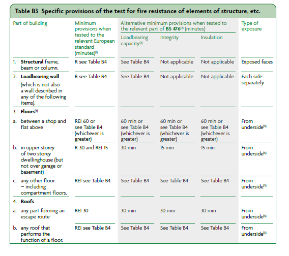
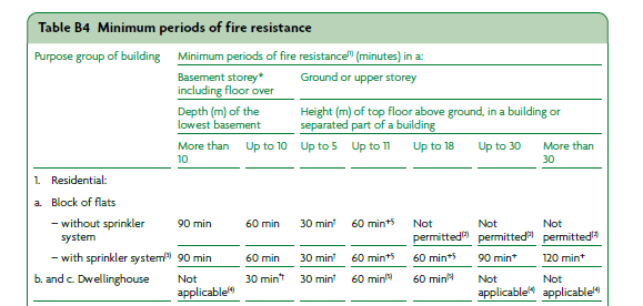
-
Hi @daunker Yes, it's out of genuine interest and not intended to be any form of criticism. There are few folk floating about on BH that have designed a lot of these structures so was curious how you SE was making it work. I'm particularly interested in the conversion of these types of structure and their nuances. The photo you posted sparked my interest as the frame looked slender, purlins were relatively small looking and I could not see any restraints to the rafters. I see it's a propped frame..central support to the rafter. This relieves the bending force in the rafter thus you can make it smaller. One consequence of this is that the frame tends to sway more in the wind and these types of frame can be more prone to buckling under certain loading conditions.. they are more sensitive and more likely to misbehave. I would hazard guess that the critical loading case is downwards load plus wind load for this frame and this is reflected in the diagram that shows the deflected shape to some extent. I can quite see the load case used but I assume that at some point the load case of downwards load plus wind has been checked as it's often critical on a frame like this. The bending moment diagram (first diagram) shows the bending forces in the members. You can see that at the bottom of the columns there is a bending force which is a bit less than at the eaves connection. I think your SE has assumed that the columns are fully fixed at the base, this makes a big difference to the analysis and thus you have to be sure that the base connection is really fixed and not just a bit of kid on fixity. Presumably you have investigated some of the column bases and checked their size, the base plates and bolting / encasement? Sometimes you get fixed (Constrado) bases if one of the walls is near a boundary. I may not be relevant but the extract from the report mentions that the existing members are 152 x 76 RSJ's, later in the hand calcs the member sizes are referenced as 152 x 89 UB 16's? I would assume that the sections used in the design checks match up with what you have. Lastly it may well be that your SE is taking into account other factors (maybe connection to the other structure that will remain for the life of the building) that we can't see and thus the frame will be good to go!
-
@saveasteading raises some serious safety issues here. I would love to see how your SE is justifying this. It may be that your milk parlour was over engineered in the first place and you are certain of the steel grade / quality, bolt strength and assessed any corrosion that has taken place over the years. You have an old milk palour probably build before the argicultural codes of design were developed. But to give it the benefit of the doubt lets say that it was designed to an old class 4 agricultural standard. BS502 part 22- 2003. For a class 4 building the design life is 2 years. The latest update of the code has dispensed with the old class 4 as there were too many farm building collapses occuring! Copied below are some extracts from BS 5502 part 22 2003.. this code is now superceeded. To put this into context a house roof designed for the normal 50 year life span (equivalent to class 1) should be able to carry a load of 0.6 kN/msq about 60kg/m sq. Lenders expect that a house structure should have at least a fifty year life span, 60 years is sometimes mentioned by insurers and lenders. The agricutural code class 4 lets you away with half that access load. Part of the reason is that the design life is a lot less, part is to do with deflections and the roof not leaking. They (farmers) did not mind if it bent, swayed a lot under snow and wind load, you will if you are living in it. Also it could invalidate a lot of your cladding / roof covering / window warranties if you exceed the manufactures allowances for movement.. horizontal and vertical deflections.. advise you check their specifications. The other main point is the snow loading. For a class 4 building it is only 22% of the design snow load of a house. Hopefully you can now start to see where the safety issue requires closer examination and why I and others? are curious. Also there are restrictions on how close a low class building can be from a highway, this is to ensure that if it does collapse it reduces the risk to the public. To explain a bit. Pretty much all structures are designed on the basis of probablility of collapse and consequence. A flood prevention scheme for farmers fields may be deisgned on a two year probablility of a flood event occuring (only live stock get killed), a house on 50 years (a few people get killed), a dam above a town / city 200- 500-1000 years (lots of people killed) and so on. Now the access load on a farm building is reduced from 0.6kN/m^2 to 0.3kN/m^2 using the same principle. To summarise and to turn back to @saveasteadinghow do you make / justify that an agricultural building steel frame of a different class and designed (if at all) for lower loading can now suddenly be able to carry the design code loads and life span that are required for a house? unless the steel was over engineered in the first place, the foundations have been investigated and proven to be of adequate size to carry the extra loads and the steel and base fixings have not been compromised due to corrosion and will not be in over the design life of the house?
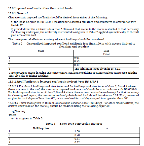
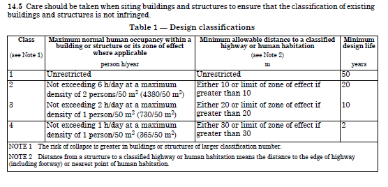
-
Hope this helps. If it's a chalet bungalow then you may stand back in the garden, look at the roof and think.. hey there is not much load to hold up there.. and often you would be correct, thus a simple beam would be in order. The vertical loads on a typical chalet of (normal construction) are easily calculated and the design is simple. As the loads are small then often you don't run into difficulty working out how to support the point loads from the end of a beam. All the SE needs to do is talk to the Architect to understand what is required, see if the drawings they have can be overmarked without requiring other details particular to the structure, determine the vertical load, specify the beam say and over mark the Archictect's drawings. Maybe all done for £500-£750 But..the first thing the SE will do is to look at the size of any openings you propose to the external walls and see how they will impact on the sideways stability of the building. Next they will look at whether you are removing any internal walls and if these walls, although probably not load bearing (on a chalet the roof tends to span over the external walls) are contributing to the stability of the external walls (lateral restraint) and / or contributing to the overall horizontal stability of the building (racking / shear wall) .. so it does not blow over in the wind. Last but not least. If you have a say masonry walls then perhaps on the rear elevation you have a window and a door at the moment. Quite often folk want to lower the window cill and put in French doors. This leaves a slender piece of masonry between the now the new doors and when you check this it often fails under horizontal wind loading. The concept here is that if you are turning a wall that is connected to a return wall (thus stiffened up one vertical edge) into a stand alone column then this needs close examination. For the curious. Often when these houses were built say in the 60's they had good solid metal / timber window frames that stiffened the masonry and the original designers took advantage of this when designing the walls. These get ripped out and replaced with uPVC or Aluminium. The modern windows are isolated thermally and are fixed with slender brackets thus no longer stiffen the masonry. This means that you can't just use the original design assumptions of restraint to the masonry. If horizontal stability is an issue the SE now has to do a lot more work and drawing. The £1500 can be justified in this way. Hopefully this helps you form a view on the fee level. All the best with the project.
-
Ah.. but how thick are your firring pieces at the thin end? That is what you need to check first. Be careful here and make sure your builder is not telling you a story or you have not understood how the loads are transferred from the OSB3 to the main joists if DIY.
-
@daunker Interesting. But a few questions first. Is it a planning condition that you retain the existing structural frame? That frame from the one photo does not look like it will support a domestic roof load .. 50 year design load as opposed to even an old class one agricultural loading. Can you tell us a little more? Also, the steel frame looks like it will deflect a lot horizontally and if you are relying on it to restrain the walls then the walls will crack if the design is based on this premis. A standard deflection limit of an agriculatural building is column height /100. With blockwork it's height/300 sometimes more. Farmers built these things to just stand up and no more, (they did not mind if the roof dripped a bit - excessive deflection ovals out the fixing holes in the roof cladding so the roof drips a bit in places) to house cattle/ sheep etc not their family.. the main farm house was often of a much more robust construction, houses for workers less so. It may be that your SE has designed this so that the steel frame appears to be intact and doing the work to keep the planners happy, but has actually designed the masonry to stand alone thus you have the solid 9" blockwork. Check with your SE before changing the block specification as going from a solid wall to say a cavity reduces the effective thickness of the wall to resist the loads. It's an interesting topic this.. how you convert agricultural buildings into a house.. made more interesting design wise by the planning constraints in England.
-
What are you proposing to build? If you could provide more info you'll get much better feedback on what you maybe need to pay (fair rate) to get your requirements met. It may be that your project is really simple, maybe one simple beam and some written specification. But if more complex then finding the right SE will often save you money in the long run. SE's do a lot more than just calculations and over mark drawings. Experienced ones (SE's) have a wide range of knowledge for example.. how different Builders work, they can pitch the design to make it easy for the type of builder that you maybe have in mind and this often results in an overall saving. Remember that a good tradesperson will cost about £1200.00 per week each. An SE can easily save you that amount if they put the thinking time into your job. But if you have a race to the bottom then the SE will give you a low price, over design, caveat the drawings heavily and you will pay more later at the end of the day. A point I always make is that a good SE who understands your project can often easily save you more than their fee, sometimes a lot more on top of that, if you get them in early in the design process.
-
That's fine as the vertical stud (loaded parallel to the grain) applies load to the sole plate. The load the stud appiles to the wall plate is perpendicular to the grain of the sole plate. Thus the packer should have the grain running in the direction from the inside of the wall plate to the outside. If the joiner has just cut a packer off the end of a timber (cross grain) the packer timber grain will be running vertically and just fall apart. Hopefully your joiner has not installed the packers with the grain running vertically.
-
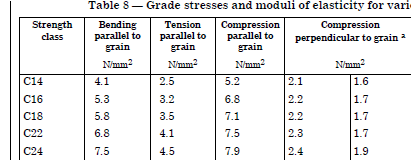
The vertical load comes down the studs. Yes, the OSB shed's load but ignore that conservatively. The studs are checked not least for the following load cases: 1/Full roof and wall loads plus anything else acting as a downwards load. 2/ Other case which include wind and snow. The main thing here is nearly always load case one. The compressive strength of timber is much more when axaily loaded parallel to the grain. The critical compressive (bearing) check is at the base of the stud. Here you have the stud loaded parallel to the grain bearing on a horizontal wall plate, the grain of the wall / sole plate here is loaded perpendicular to the grain and this has a much lower compressive strength. Conservatively assume that the load goes straight down and does not disperse through the sole plate at 45 deg. Thus if you use a timber packer under the sole plate of the same width as the stud and same length as the width of the sole plate with an equal or greater compressive strength perpendicular to the grain.. that will satisfy the bearing check. If in any doubt get some 50mm (same width as the stud) wide oak / hard wood and rip that down to make a selection of packers the width of the sole plate. Soak them in preservative after cutting for good measure. Have copied part of a table from the BS below. You can see here how the compressive strength of a timber is much more when loaded parallel to the grain as opposed to perpendicular. You can see for a C16 the compressive strength of the timber loaded axially is 6.8 N/mm^2 and the the sole plate (loaded perpendicular) is 1.7 N/mm^2. Fill in any gaps with something else, maybe add the odd extra packer if you have any doubts about the above and get some extra load spread due to the load sharing properties of the OSB / sole plate / bottom rail of the panel. You may want to do this to spread the load more evenly over the underbuilding if you feel this may be an issue. For all .. do not use plastic window packers under your timber frame as the are not solid.. they are for windows.. not structural loads. You can buy the right plastic packers for timber frames on line etc.