


Gus Potter
-
Posts
2340 -
Joined
-
Last visited
-
Days Won
29
Everything posted by Gus Potter
-
A few random thoughts. I'll start with what may be going through you SE's mind and their thought process. The 100 x 100 lintels tend more often to be what we call non composite lintels. In other words they act like steel beams say that "stand alone" and don't rely on having masonry above that interacts with the lintel / beam to create an arching / deeper beam effect. The 65mm deep lintels work in a different way, often compositely and they need to interact with the masonry above. In other words they are two different animals... but look very much the same. Now if you don't have say 4 -5 courses of brick above the lintel then you often need a non composite lintel. Also, on alteration work no matter how well you repoint the gap over the lintel you'll never get the same "bedding effect" that you get when you are laying the wall for the first time. You new mortar will shrink away so the brick above won't interact with the lintel to develop the composite action. In other words you can rule out a composite lintel on most alteration work. The difference in load bearing capacity is a lot so don't get caught out. You SE has probably also thought about how you prop the wall when you are doing the work and how much space you have to do this. They have probably also thought about what is above.. are there point loads from floor joists, maybe other stuff above, a door over lapping the opening, all sorts of permutations.. and that again rules out a composite lintel.. hence the 100 x 100 that is a non composite lintel. The 100 depth is say enough to carry the final loads but shallow enough for you to prop it? Before you go ahead mull this over. Be very careful about putting in any lintel orientated in a different direction from the manufacture's intention.. trouble ahead! Your weird 20mm cavity! What you probably have there is what we call a collar jointed wall. The two leaves are tied together with brick ties at much closer spacing than you have in a normal cavity wall and the gap between the leaves is filled with mortar... the gap is usually 10 - 20mm to allow for variations in the brick widths.. hence the 20mm you are observing. This allows you to design the wall using it's full thickness so you get more bang for your buck. In summary it looks like your SE has put a bit of thought into this. I would lift the phone to your SE before you start deviating from the design.
-
Fixing timber firring pieces to steel joists
Gus Potter replied to Modernista's topic in Garages & Workshops
Good solution Mark. +one -
That is a stunning photo of the ground! Me too never seen such clear definition of the layers and the distribution of the particle sizes. Looking good Nod.. the rain will stop! Dave.. you are a bad man!
-
Hello Marlin and welcome. You'll get plenty help here. There are a few folk that have joined since this thread was started. It's a guess, but some will be along shortly to contribute in terms of how you design this structurally for a domestic application and a few tips and hints on the insulation details and so on... and many more. In terms of structural design the main difference between agricultural design and domestic design is the deflection limits you work with. In terms of detailing you have a bit more work to do to reduce cold bridging, detailing around the openings and damp proofing, all surmountable though. Think of it like an office building.. meets the same standards very much as a house requires in terms of environment and insulation. Ok. To get you a bit further what about posting your sketches, make sure you dimension them; include the roof pitch, show windows / doors and the heights you want internally, where you want the openings and how big you would like them to be. Also show the ground levels as this impacts on the column height down to the found as that is one key parameter when determining the steel section sizes. What kind of ground do you have, clay / chalk / rock etc. If you want.. provide your location. You can give just the first part of your post code. Then we can see roughly where you are in the country. Also provide the site altitude and if close to the sea.. if next to a cliff or at the top of a long exposed hill let us know that and then we can get a handle on the wind and snow loading This will allow for example for folk to give you a rough steel size for the main portals and a ball park size / spacing for your steel purlins and wall rails. There are many variants but you need to start somewhere! For your steelwork you can go the whole hog and work all this up to a full set of fabrication drawings, material and bolt list with numerical control files and then start farming that out to fabricators. All they need to then is to fabricate as they have no design input at that point. The numerical control files are a text file that is accepted by the software on most advance cutting and drilling set ups. Having these lets you go to big fabricators for a price too. But the NC files are not essential as most smaller fabricators just want a good set of drawings. A good set of drawings comprises. General arrangement drawings. What are called assembly drawings.. these are drawings that show say beams with their end plates say and the weld information, a plate and shaft set of drawings. These are drawings of each individual plate and beam. Small fabricators may buy in the plates and shafts and make their money on the welding / painting/ supplying the bolts and so on.. again many variations on how you can go about this. Now that is a lot of drawings but we use software to do a lot of the heavy lifting and drawing production. In terms of PDR the planners are interested in what it looks like from the outside rather than the skeleton of the building which is often covered? Keep posting.. interested in your ideas.
-
@Ben Weston 1/ Take everything the brickies say with a pinch of salt. If you have large bifold doors say then you could have point loads and need at least something with a bit of strength under areas of localised loads. Your average brickie is not going to spot this. A few may do but it's evidence you need not "blarney". Question.. do you let the brickies advice take precidence over BC and the SE? 2/ To get the best economy you need a really level found to build off + /- 5.0mm if you only have a couple of leveling courses before the masonry becomes visible. In practice this does not often happen. 5.0mm is too tight a tolerance for practical day to day site work on concrete founds in the domestic market. It will be hard to achieve a level bed for the engineering brick with only one course of trench block and still comply with the maximum and minimum mortar bed thickness required by the codes. 3/ Practically and cost wise your founds are unlikely to be flat on the top. Expect in real life a variation of some + / - 15mm often more .. if you get a hot day then the concrete won't flow so well, a really wet day and the folk laying it will want to just go home. Solution. Use 7.0 N dense blocks laid flat and bonded to get the coursing right and a level bed. Then put your Engineering brick on top.You will get a bit more play in the mortar bed and this will make it easier to level the coursing before the engineering brick. It may be that the engineering bricks are forming a damp resisting function particularly if matching into an existing building that has no DPC but blue / engineering brick as the DPC. If this is the case then they could be decorative and it needs to be spot on visually. To realise this you need to give yourself as many points of adjustment in the mortar beds under the ground as you can = more courses. In summary forget mixing and matching, stick to dense concrete block and concrete bricks if need be if it turns out the top of your founds are not quite where you expect them to be... they probably will not! Forget the one course of 3.6N trench blocks. It is false economy.
-
What is the mesh required for? Generally the A type meshes are to control cracking only rather than acting a true reinforcing bars like you would have in a reinforced concrete beam or floor slab in an office floor. You'll often see on a drawing A142, A193 or A252 meshes specified. If this is the only mesh shown on the drawing and there are no other individual bars attached to the mesh then it is likely for crack control only. The are other types of meshes called structural meshes and these start with the letter B. If you have an A type mesh then as @saveasteading says explore using plastic fibres as you could save a lot. Post more info if you want to investigate option further.
-
Do I need an architect or SE? Any recommendations?
Gus Potter replied to SarahG's topic in Surveyors & Architects
@SteamyTea Great link to the book. Ta. -
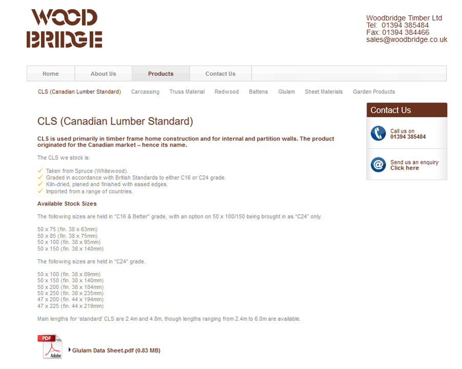
Yes it is standard stuff, nothing wrong with it. In fact most of the big TF companies seem to use it. On the practical side if you are a self builder then you have to be more accurate to fix plasterboard to a 38mm wide stud than a 45mm wide stud. In certain windy places or if you have slightly higher walls (longer studs) it can work out economically if you use the slightly deeper 95 x 45 timbers as this lets you keep a 600 centre stud spacing rather than going for a 400 centre stud spacing. It's not just the extra timber as when you have 400 centre studs you get closer repeating bridges which impacts on the insulation performance. The main thing is that an 89 x 38 mm stud has different load bearing and wind resisting properties compared with a 95 x 45 size. Would be a shame to do a lot of work and BC knock you back. Best to check first.
-
That looks interesting. You may have to put a bit more thought into how you make it safe and comply with the accessibility requirements, especially if it is a new build. It's not just the stair on it's own but also what you have at the bottom / top of the stair / corridor widths and so on. That is why maybe why you find folk backing off a bit in helping you with the stair design. You need to provide the whole picture in terms of top and bottom landing space / doors in proximity at the top and bottom of the stair / opening direction, the size of the landings at the top and the half landing and so on. A few things to check are for example in Scotland: Are there gaps more than 100mm between the treads and between the handrail balusters. Is the hand rail / baluster assembly climbable? What space do we have at the top and bottom of the stair, where are the doors, are there any fire / smoke protection measures required, can we fit hand rails and where do we need them and what width of stair is required. If a new house then disabled access requirements will apply. Basically in Scotland you need to make provision for a future stair lift. The regs require space at the bottom of the stair and at the top to park / access a standard stair lift. But you can now get ones that are self parking so that makes life a bit easier. Stair lift technology has improved a lot over the last few years. I would try if you can to put together something that shows more information, maybe that covers the above and see how you get on. You can always test the water by posting here on BH. Don't worry if you can't understand the stair regs at your first attempt.. very few, if any, do, myself included.
-
Hope this helps a bit. Just watch the timber thickness.. as in an 89 depth it is often 38 mm thick as opposed to 45mm thick that you get with grade C16/ 24 95 x 45. Please ignore the branding, it's just a snippet I have in one of my data sheets, makes for easy reading though.
-
Wishing you all the best. Looks worth the effort you are putting into this. Keep us posted!
-
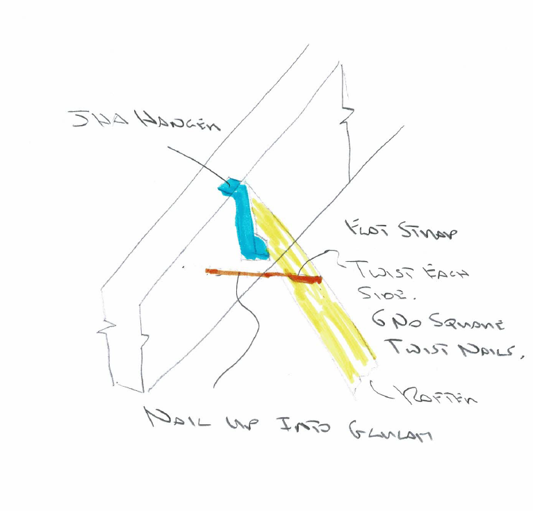
What about this? Have attached a very rough sketch. Notch bottom of rafter< 25% Use JHA Simpson hangers wrapped over as you have shown. These take the shear loads. Buy some flat galvanised restaint straps 2.5mm thick or round about. Get a vice and a spanner and gently put the 90 deg twist at each end where you need them to be or if you want the full bunnah get Simpson to make them for you. Try if you can to get at least 6 no square twist 30 x 3.75mm into the rafters maintaining a 20mm edge distance to the timber. Much will depend on the rafter angle, the shallower the more meat of timber you have to play with. The twist strap will sit flush with the bottom of the Glulam and tie them together at this level. Get 3 - 4 sq twist nails nails up through the strap into the underside of the Glulam. If you put the strap over the top of the timber you'll need to scab extra timber to the side to fix the sarking as the strap will foul the sarking nails. Food for thought?
-
Do I need an architect or SE? Any recommendations?
Gus Potter replied to SarahG's topic in Surveyors & Architects
@SarahGThat is a good place to start. Often if the builder knows that someone is keeping an eye on things for you then this encourages a good standard of workmanship. Also, if you set it up right and say to the builder that you have engaged someone who is fair minded, even handed and impartial then it gives the builder confidence that if they get a bit stuck they can call on your advisor for guidance... feel able to lift the phone and be able to discuss say problems / unforseen issues on site. It's about working as a team. This to some extent this de-risks the job for the builder as if say there are extras they may feel that they will be paid for them if justifiable. It also de-risks it for you too in that the builder will know that any spurious extras will be resisted. -
MBC Frame - Windows - When to order ?
Gus Potter replied to bob the builder 2's topic in Windows & Glazing
Hi Craig. Agree with what you say, especially with bifolds, big sliding doors. It only takes a bit of poor joinery work on the kit and things will settle, timbers that have got too wet on site and suffer from excess shrinkage, move off the square, bit of settlement in a found and if you have a combination of these small movements in aggregate you often get enough to make things start to stick. Unfortunately it's often the window / door installer that get the blame first.. last person on the job is often the first to get it in the neck.. money can be unjustifiably withheld. I would still though be careful about jacking as later if you say get a fall of snow, or say full load on a balcony above and things dry out more, masonry further shrinks then it could all just drop back down again and loosen things off even more. -
Do I need an architect or SE? Any recommendations?
Gus Potter replied to SarahG's topic in Surveyors & Architects
Different takes on approach here from Peter and Charlie. BH is about say buying your first house/ flat, doing it up, then..maybe self building or just sitting back and saying I did that once and that suits me, innovation, the excitement and that deep personal reward you get, feeling of achievement. I think Charlie and Peter to my mind have identified part of the problem. Charlie mentions new SE's coming in not knowing about the building regs in detail, it's a valid point.. on a social level it could be defined as the division of labour, see for example Adam Smith.. The Wealth of Nations for a bit of background. In summary we all have become more specialised in what we do as the population has grown and now we are arguing the toss about a few quid between Architects and SEs etc. We used to draw on paper, now we use a computer.. it's just a tool. I can spend a day, sometimes more on cad just working through a detail that will last for 50 - 100 years more I hope! Before I could go through a wad of paper. Folks on BH.. it's the thinking time that counts not how fast you can move a mouse. @CharlieKLPbut the same can can be applied to young Architect's and other young designers. It's not their fault that they maybe have less intuition about how to realise their designs economically so that they will actually get built. My advise to the folk on BH is this. Rather than look to save everything you can on professional fees find the right fit for you. You need to work to find the right person for you, they are there and they will save you money in the long run. Bear this in mind. A good tradesperson will cost you £250.00 per day at least. Say £1250 a week. A good designer only needs to save you one weeks labour on say an extension and they have washed their face, never mind any material savings.. and here we are splitting hairs on how fast you can draw in CAD or look up the building regs to check something! Don't get hung up on a few hundred quid on design fees and how fast someone may be on cad. The test is this. Can my designer deliver what I want and save me more than I'm paying them any extra in fees compared with just getting a bog standard "off the internet" design. -
MBC Frame - Windows - When to order ?
Gus Potter replied to bob the builder 2's topic in Windows & Glazing
Pity your bifolds are sticky. Ok a bit of maths first!.. and a bit of a story.. grim at first but good news at the end! @laurenco Say each of your bifold panels are conservatively 800mm wide, you have 3 panels. Thus from the top outside corner of the doors back to the roughcast on the main house wall you have a distance of 2400mm. Above the bifolds you have a section of rendered construction, above that the frameless glass, more forgiving often in terms of movement than the bifolds. Now the panel above the bifolds will be fairly stiff on the inside and to some extent flexible between the inner and outer rendered layer. The load from the balcony will likely be on the inside and you'll probably have some flexible ties so any movement within the panel structure above the doors won't immediatly manifest as cracks in the render. But assume (conservatively) the panel above the doors maybe acts as one unit and rotates about the point where the bottom of the rendered panel meets the main house wall at the level of the top of the doors. Now assuming the panel above the doors acts as a unit then if the outside corner of the panel above the top corner of the doors drops by 10mm that means that the panel rotates downwards by tan (angle) = 10 /2400 = 0.24 degrees. If the panel above the doors is 900 mm high then at the point where the bottom of the balcony glass meets the main house wall you could expect a crack to be at the top end of tan( 0.24 deg) * 900 = about 3.8mm.. not a lot actually and hard to see. That may be why you don't see massive cracks at the moment. Even then you would be hard pushed to distinguish this between movement crack and a shrinkage crack. Going back to your design and looking at it conceptually there are a few ways of designing this as an SE. You have the balcony above so a bit of load there, doors that are sensitive to movement, a timber frame that shrinks and swells season to season and also dependant on how warm / cool you like your house.. it's a "living" thing that reacts to moisture changes. Timber frame.. it's going to move about quite a bit! a lot more than 2.0mm on standard stuff, any cantilever arrangement is going to move a lot more than 2.0mm. A first glance to design something SE wise like you have I would ask what your budget is. If you are very tight for cash but still want that type of bifold arrangement I would look at making the outside corner of the bifold as a hidden structural post / column. If you want, look up a window bay pole on the internet that will give you the jist of it. The thing here is that you remove the cantilever effect, reduce significantly movement, make significant savings not just on the balcony, beams but also on how you connect the produding balcony back to the timber frame. MBC may have made this "baypole" assumption so check. The design philosophy is often lost in the wash and that is how these things happen. Alternatively you can go for everything cantilevered out from the main house wall, using the first floor as a means of supporting the cantilever. You will get a lot of movement here though. If you use steel and ordinary bolts then the bolts go in holes of 2.0mm greater diameter than the bolt size.. the bolts initially can move about before they take up their final position. To sum this up. Your starting point here is to go back to the structural design and see how it was intended to work, what caveats the SE specified, the design deflection limits. If you want post more info it would be of interest. If the SE has gone for the "bay pole concept" .. a column at the outside corner, could just be a heavy aluminium corner frame? then you need to check that the bifold supplier has been made aware of this and implemented that SE requirement.. if not you have a major safety issue you need to address. If you check this structural stuff out first and make sure there is not a fundamental structural problem and all is ok then I would, as a next step, get a hold of a local window / door installer that knows their stuff to give you the right advice. It may be that all you need to do is take the beads off, square the frames up by repacking the glass with the plastic spacers... one days work and that will be you for a good few years until the moving parts wear a bit, then get the same guru back! Sometimes things jamb as the spacers between the glass and frame at the top of the door come loose and slip down so the frames sag and get sticky. @craig good point about scooping out the foam and how it hardens up. Now sure about jacking stuff as a first choice personally until you really get to the root of the problem. Lifting things locally could move other structural stuff off their friction bearing that we rely upon and that could lead to structural instability.. you can lift several tonnes with an accrow one you set you mind to it.. great fun but there are concequences. That said, once you understand what the problem is then controlled jacking and packing is a good potential solution. -
Do I need an architect or SE? Any recommendations?
Gus Potter replied to SarahG's topic in Surveyors & Architects
Hi Sarah There are few SEs that start as SEs but then branch out into the Achitectural design side. Structural Engineering is often described as "The art and science of design" The focus word here is "art" There are few Architect's (Architects practice the art of design primarily, but also the science of design and many other functions too.. it's a long list) that start as Architects but then branch out into structural design. I work / collaborate with one who is spot on in SE terms.. so know of at least one.. they do exist but they are not that keen on doing calcs. If you know what you want then there are a few SE's that will do your building regs drawings and the calcs as a one stop shop. True Charlie not all SE's are that keen or know about the detailed regs say relating to noise transmission etc.. the building regs are wide ranging! But yes everyone has a different skill set. @SarahGkeep searching and you may find someone you hit it off with and can deliver just what you require. -
I'll leave commenting on the change in rafter centres etc for another time. Was on site last week and saw a lovely pile of 25 lengths or so of C24 timber 145 x 45. Builder says.. that was cheeper than C16! Story goes. Everyone specs C16 the lower grade so that grade is much in demand.. merchants put the price up and don't happen to mention that the higher grade is cheeper. No friends in the desert eh!
-
@saveasteading Hiya. My thoughts in line with your text and in green colour to give it a go. About to order the timber for the stick build section of new build (replacing demolished section.) 1. I am trying obviously to get the most efficient design to save timber and labour. Gus - Good effort I can see that a kit build company brings in whole wall panels, places them on a sole plate, then straps a top wall plate on to hold it together. Gus - Yes normal practice, but lurking below the surface there is a contractual reason for doing this. The TF company base their quotes and design on the assumption that dimensionally and level wise they can erect the panels on a controlled interface.. the sole plate. If the TF company are erecting they will send their surveyor out to check the dimensions and levels. But with stick built, can we not build the studs straight onto the sole plate, and then a single top timber (except where doubled/trebled as lintels etc)? Gus- technically in terms of the sole plate if you look at one panel alone.. yes if what you have below the sole plate has a higher compressive strength perpendicular to the grain than the sole plate timber once you have taken into account the load spread down through the depth of the sole plate. But in practice you will often find it very difficult to comply with the level tolerance and dimensional tolerances that the TF panels require. That is one, probably the main function of the sole plate. Call the top timber of the panel the top rail. Above that is another timber.. the head binder that connects the panels together. But.. the head binder serves a number of purposes. For example it adds a bit of stiffness to the head of the wall for. If one rafter is moving more than others it helps shed and share the load out. Also, the panels often work to resist sideways (horizontal) wind loads and the head binder is required to make the individual panels work as a whole rather than individually. This makes the whole system more efficient. Head binders can be long so less chance of say a truss clip falling next to a heavily nailed joint. Remember that a timber can only take so many nails before it splits. Saves wood, saves labour, reduces cold bridge, increases insulation area. I think this may just be a standard detail that is not questioned. Gus - always good to question and share knowledge. This is the only way we learn to build better, safely protect the environment. Now with modern cheep laser levels your local builder can achieve much better control over the tolerances. But! not all builders can do this. Yes it is a standard detail but if you can design for a higher standard of workmanship then @saveasteadingmake sense. If you could remove the sole plate and replace with insulation then there is an obvious advantage. One less joint. more air tight, more insulation and less shirinkage over the panel height. Oh.. timber frames shrink, the outer leaf of masonry less so. Timber shrinks much more perpendicular to the grain (the sole plate, bottom top rails and head binders) than along its length. Thus when we design TF's of two or more storeys we need to look at how we orientate the timber in the wall panels and within the floor zone (the rim beam for example) to minimise shrinkage and differential movement that jambs doors/ windows and causes other "horrible" things to happen. 2. Any idea why there should be a dpc under the sole plate of Internal Walls? Architect and Engineer dont have it but a potential joiner's QS has included it. The wall will be on a concrete slab with dpm below it.......just checking I am not missing something. Gus - Good practice. If your timber is sitting on an internal concrete slab well protected with a dpm and no condensation risk then all boxes seem ticked. But if you have a burst pipe the slab could be soaked for months before it dries. Best to isolate the timber from a slab that could suffer from a plumbing problem that could compromise a major load bearing wall. The houses we are designing should last well beyond our lifetime. at some point someone will get a water leak. 3. Simpson rafter hangers with adjustable sloping foot.....cost about £18 each. !!. x 50. I cant see any competition to this supplier. Know any alternative or something cheaper. Ah.. generally longish rafters, can take about a 25% notch depth before shear at the ends becomes a potential issue. You could use a standard Simpson JHA hanger.. PROVIDED they are not intended to also act as ties. In the round if it is up at say ridge level you can sometimes use a cheep standard hanger and cheep steel strap to provide the tying required. You can even use a timber up at the ridge as a tie if Architecturally acceptable, you fix plaster board to same timber.. free lunch! 4, Inverness area only....where is the best timber price at the moment? The prices seem to have eased, and are about £550/m3 for big timbers. That is list price and should come way down for a big order. Do John James sell direct? Loads of mills doing C16, but is it treated? One local mill said they can't beat the merchants and only do special commissions. Good news on prices calming down. Also, as the rafters become shorter in the triangles of the valleys and hips, is there a stage at which we just bang in 4 nails? Yes it's often called loose infill, less than 1.0m length and uniformly loaded it's pretty much infill.
-
Hi Joe. Thanks for the compliment, much appreciated. Pretty much every time I browse BH I learn something new. Some folk like numbers, some less but I try where I can, like a lot of other posters, to weave a lay persons "rough guide" and tell a storey when it comes to SE stuff. BH is supposed to be fun and friendly. I too struggle with some of the numbers especially when it comes to the insulation side of things but keen to learn at my end. Joe I think I can see where you are coming from in that you are looking at each individual cladding board? But even though each board will be counter acting the effect of the one above or below they still have the net effect of loading the truss at it's outside edge. Think of the truss as a column. If you load a column about it's centre all the load goes straight down so you don't have a load set off from the centre of gravity of the column thus no initial bending effects. The same applies if you have a joist bearing onto a brick wall. If the point of bearing is not dead centre over the wall it will cause a bending effect in the wall as well as a compressive load. That's a good point you make about nails at 150mm centres and that they seem close at first glance. However when we design timber frames and check for lateral resistance, to check the house won't move sideways, the starting point in say BS 5268 is to begin with a 150mm nail spacing around the edges of the boarding. Then we modify the nail spacing if need be. 9.0mm OSB is pretty thin and if the nails are too far apart then the OSB buckles not least between the nails, a bit like the thin backing on a kitchen cabinet. The backing on the cabinet keeps it square, same principle applies to a timber frame, just a TF is often more expensive? I have copied, some info below. You can see in coulmn 2 the starting point for nail spacing internally and around the perimeter of the boards.

-
Hi Mike. Depends what side of the fence you sit on if so inclined. It could be properly designed SE wise but no use whatsoever to folk on BH in terms of buildability / labour cost. Your bang on with it being difficult to fit solid insulation between I sections for example. Now your 50mm nail spacing on your racking walls? That I have not seen before but every day is a school day. It's interesting for me to see such close nail spacing. For example the racking forces are probably quite large.. so this will result in a fair bit of panel overturning effect, lots of uplift forces = plenty tying down straps and associated fixings. Also I'm curious as to how you SE has been interpreting the codes and taking account of what we call second order effects.. just nosey.
-
I would bite the bullet and get an SE in for a look at this. While there are a good few good competant builders out there.. there are less / few that have a true understanding of overall building stability, it's not really their brief so you can't knock them. The main thing is to recognise is that even though you may be looking at the vertical loads you need to hold up, the pillars and even innocuous bits of wall, may be providing horizontal stability to other parts of the building. Often you find walls that don't carry load from above.. non vertical load bearing walls. But these walls are still load bearing walls.. making a major contribution to the walls that are carrying vertical load. They prevent the vertical load bearing walls from buckling and / or to resist the wind loads that want to push your house over like a pack of cards. For all it will cost and in the interests of keeping you all safe, ask an SE. They may even suggest a cheeper way of doing it. If not you will have a correct design that you will be grateful for when you eventually come to sell the house.
-
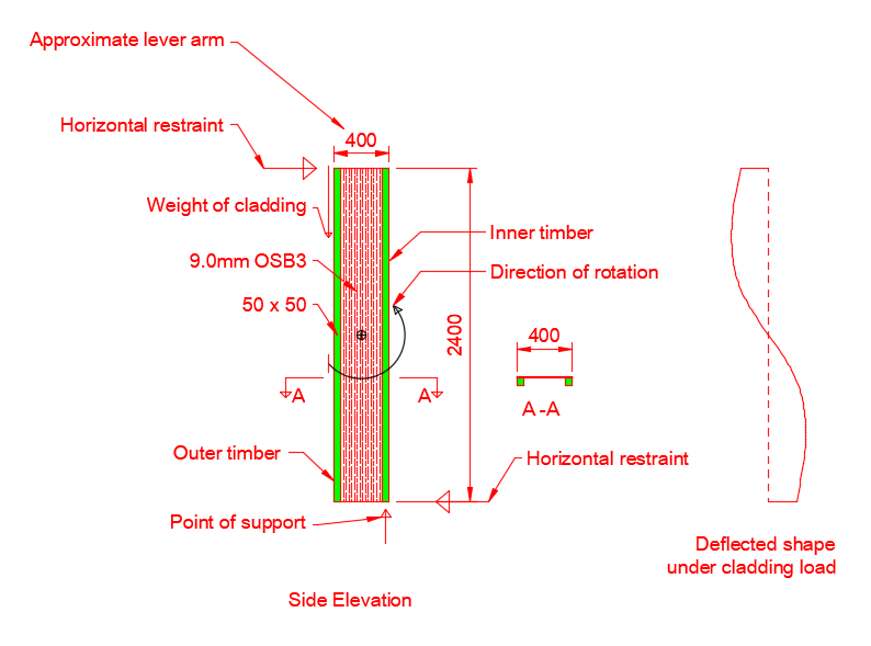
Hello Hill Runner. Great place, high up so next stop is the moon. I'm down the road/ hill from you but have you bought a gold pan yet? If you have attended to all the gutters, down pipes etc and checked the ground levels are not bridging the DPC what about strapping the walls with 50 x 25 treated timber. Fix a bottom and top rail and verticals at 400 centres. Pack the straps off the wall say 5.0mm with a small cutting of DPC behind. How old is the house, does it have a bitumen DPC.. what is the construction of the external walls? Ah saveasteading, good point, made me think. To saw an 8 x 2 structural timber out of a 16 inch log after cleaning & stripping say requires four saw passes. But to plain saw a 2 x 2 requires another 3 passes of the saw? So more sawing to produce smaller timber out of the same size of log. But in real life the smaller logs are used for the smaller sizes. hey ho. The point is that you need more sawing? Also the surface area is greater relative to the cross section area of the smaller timber so you may need more preservative and a bit more handling? Maybe this goes some way to explaining why smallar timbers cost more than standard large ones per volume of timber? Thanks Dave for the Larsen truss, great spot and Steamy too and everyone else. Lastly to Mike, but setting aside a real good practical point from Mike and for a bit of fun I have had a look at the Larsen truss, how it works to some extent in terms of creating a twin wall so you can create depth for insulation. I've tried to capture some of the main points but..! Mark et al please chip in if you think I have missed something or made an error as no point in posting incorrect stuff. Here goes. I'll put some qualatative numbers to this. Work out the weight of the cladding, say another layer of OSB, battens and some timber shiplap. Shiplap thickness 14 mm. Timber density = 420 kg/m cube 0.014 *420 = 5.9 kg/ m sq Vertical 50 x 25 battens to create gap between board and OSB @ 400 centres. 0.05 * 0.025 * 420 / 0.4 = 1.3 kg / m sq OSB 9.0mm thick 5.5 kg / m sq. Sum of above = 5.9 + 1.3 + 5.5 = 12.7 kg per sq metre. Convert kg to kilo Newtons 12.7 * 9.81 * 0.001 = 0.12 kN add say 25% for "other stuff" like insulation and self weight give 0.15 kN per sq m.. not a lot as 0.15 kN is about 15 kg per sq metre. Over a 2.4m height this gives a load per metre run of wall of 0.15 * 2.4 = 0.36 kN ~ 37 kg. Now because the cladding is off centre from the point of support it causes a bending effect in the vertical section. The bending effect (the bending moment will be ~0.15 * 0.4(lever arm) = 0.06 kNm this is very small. For example if this was a domestic floor engineered I joist we design for the dead loads (self weight, flooring plaster board etc) and live loads, you and others. The live load is 1.5 kN/m^2 (~150kg) for a domestic floor so the bending moment is calculated for the uniformly loaded floor joist under live load space at 400mm centres as follows. Spacing * Load * length squared /8 =0.4 * 1.5 * 2.4/ 8 = 0.432 kNm which is more than the above bending force from the cladding weight. You can see that the bending effects from the cladding weight probably don't govern the design. Look now at how the cladding weight gets to the point of support. For every run metre run of wall we have about 0.36 kN..(36 kg) of cladding etc not a lot. There are battens at 400mm centres so each batten has to transfer via the nails 0.36 kN *0.4 = 0.14 kN over it's height. A very small amount. Now a 2.7mm diameter nail from 9.0mm OSB into a C16 grade timber has a shear capacity of some 0.05 to .08kN capacity. So the minimum number of nails will be 0.14 / 0.05 = 3 number. Again you can see that you don't need many nails to do the job to transfer the cladding load via the battens to the 50 x 50. We can set that aside for now. If using a cement board say we may need to revisit. But there is no free lunch! Firstly for it all to work the load from the cladding goes into the 50 x 50 but if you only have 3 nails up the height the 50 x 50 will bend like fury and it won't work. For it to work as a truss / I joist you are looking at nails at 100 - 150mm centres to connect the OSB to the 50 x 50. Then you are on the ball park. You may have a wind load acting on the cladding and this has to be resisted. Wind loads could be 1.0 to 1.5 kN/ sq metre so they have a big effect, much closer to a floor joist type live loading. This could often be the governing factor in the design. Lastly as @MikeSharp01 points out there are practical things that need consideration, how do you fit the insulation, what type and so on. Also, you want the 50 x 50 to be stiff, you don't want to be trying to fix cladding into a small timber that bounces all over the place. I think that although you can show that the forces can be accounted for structurally and you can "technically design" something lean you need to look at this in the round, particulary the buildability, labour cost and how easy it is to achieve a consistent quality of workmanship. I think this is the key to getting this to work.. is the practical buildability side. That said it's a great concept to consider if you want to achieve low heat losses.
-
This is a off topic but @SteamyTea makes some good points. Also if you look at @zoothorn posts, it's infectious, the sharing of knowledge, questioning and exploring. The enthusiasm of all is clear, everyone here is learning something, or just enjoying the collaborative thinking. Turning now to what steamy has posted, yes OT but here are my thoughts and how this enriches BH. As a bit of a back storey. I left school at 17, went to college and got an HND in Civil Engineering, worked for a few major construction companies and went self employed when I was about 22 -24 , a while ago. Built up a reasonable business as a building contractor and had a life change at 40. When I was a Contractor I always enjoyed the teaching side, bringing on the apprentices and making sure that everyone else was able to grow too. It was not easy and eventually.. Packed it all in 40 and went to University to study to be an SE. That with hind sight was probably the best decision I made... I still remember my first week at uni at and sitting there thinking.. these lecturers are giving me two things: The basics; maths, how to write and communicate etc but most importantly the tools that I need to enable me to teach myself that will set me up for the rest of my life. I appreciated this as I was older, not many kids can see this, and they can't be expected to either. During my time at uni I was fortunate to be invited to participate in reseach as an undergraduate, I was able to bring my commercial experience to bear which clearly most kids don't have.. and off the back of that I got involved in the "educational" side of things also.. and that is why I'm interested in what steamy is saying, but I'm also fascinated about how folk learn on BH, why the mods do what they do with apparently little recognition. Mods.. OBE coming your way? Steamy to quote you "Some educationalists think that courses should be developed to a more specialised areas i.e. Forensic Science, Renewable Energy, while others think a more general education is better i.e. mathematics, Physics." Steamy I agree with your view. One key for me in relation to tertiary education is that the educator.. you for example has to be skilled in the art and science of education and to be fully invested, in other words you need to be able for example to let the students see that you are enabling to teach themselves them not just delivering a lecture. Like all things in life if you can let folk see that you are doing something that is to their direct benefit then they will take notice. An educator of younger folk also need some good sales tactics! That is the true skill of an educator. I know this works as I have been lucky enough to be taught by some expert educators and have been old enough to appreciate what is going on. Now a skilled educator needs to be renumerated.. and recognised as a contributor to society.. we don't really appreciate this as much as we should in the UK. I could go on an on.. but Turning back to BH. It's a great site for all. No matter what stage in the "things to do with houses" you are at. BH is a great resource. That's it. but thanks again to @zoothornfor starting this thread
-
It does and your grass does not grow, also in my mind what is the point in saving energy if you chill the environment and thus inhibit the wildlife that we rely on. Could be the bees polinating the crops we all rely on for food, the insects that need warmth to thrive and the birds that feed on them. We should think carefully before we mass produce heat pumps and stifle the last bit / refuge for wildlife in our cities.. there could be unforseen consequences. That said though the recoverable / easily recoverable energy density? in water is a lot more than air. @SteamyTea not strong enough on the technicalities of this? can you help? @zoothorn the best place to recover heat would be just downstream of a neighbours septic tank.. just don't let on they are heating your cabin.

