Jeremy Harris
-
Posts
26430 -
Joined
-
Last visited
-
Days Won
360
Everything posted by Jeremy Harris
-
I reckon you could think out of the box a bit here. If you laid GRP over the insulation, ideally on ply or OSB to make it easier to lay, increased the layup thickness a bit to allow for it taking an additional load, then bonded on something like 6mm or even 8mm aluminium, or galvanised steel if you wanted more stiffness, treadplate in the area you want to bear a higher load, it might work OK. You would need high compressive strength insulation, but it would trim down your overall depth a fair bit.
-
FWIW, and by no means a suggestion of the correct and proper action to take, the very first thing I did when we completed the purchase of our plot, before I submitted our planning application, was to fell all the trees................... I took the view that this was removing a significant risk, and that as the trees were not (at that time) in a Conservation Area, and didn't (yet) have TPOs on them, the worst that could happen would be that a few people had a moan (which they duly did). The fact that some people had a moan led me to believe that if the trees had still been there when we submitted our planning application someone would have slapped a TPO on them, just to but an obstacle in our way.
- 12 replies
-
- 1
-

-
- roots
- root protection
- (and 3 more)
-
So can you make the top deck out of something thin and strong, rather than concrete? How about steel decking sheets, or even structural GRP?
-
There are only very tiny differences between different PIR insulation brands/types. They are all in the lambda range of roughly 0.021 to 0.023 W/m.K, so not enough to make a significant difference in terms of the thickness needed for a particular U value. Silica carbon aerogel tends to be just over half the lambda of PIR, so roughly half the thickness for a given U value, but it is a heck of a price. What's the specific problem with using 120mm PIR, and is there a way to overcome that in some other way?
-

Insulating to Min Building Regs
Jeremy Harris replied to Ian's topic in Energy Efficient & Sustainable Design Concepts
Being strictly accurate, there is no "pass" or "fail" as such, but in order for the house to meet the requirements, and so be signed off by building control, the Dwelling Emissions Rating (DER) must meet or exceed the calculated design stage Target Emissions Rating (TER). The TER and DER is calculated using the combination of the fabric standards (which must not be less than the minimum in Part L1A), airtightness, MVHR (if fitted), fuel type, any renewable energy elements, so is a balance of all these factors. The DER is calculated using the "on construction" details, to account for changes that may have been made between the design stage (when the plans were approved by building control) and the completed dwelling. It's worth downloading and playing with the free version of Stroma FSAP to get a feel for how it works, as that does flag up non-compliance at the element level with red or green fail/pass indicators. The SAP worksheet is quite complex, and includes climate related weightings, to allow for things like solar gain variation and heat loss variation over a year. The ratings are calculated by summing the monthly means of pretty much every loss or gain. Attached is a copy of our SAP 2009 regulations compliance report worksheet which may give an idea of the process (although SAP has changed a bit since, the principle is much the same): Self-Build.pdf -
What tools/electronic gadgets to set out?
Jeremy Harris replied to epsilonGreedy's topic in General Construction Issues
The laser distance gadgets are OK, but personally I'd use a tape, as it's pretty foolproof. I have an old Fibron surveyors tape that must be over 30 years old, and still does a very good job. It doesn't need batteries, either, and it doesn't go wrong if it gets wet! -
What tools/electronic gadgets to set out?
Jeremy Harris replied to epsilonGreedy's topic in General Construction Issues
Sounds easy enough to layout with a surveyors tape and a decent level to me. Use triangulation to check you have things square and try to establish one or more fixed reference points that you are certain are in the right place, and won't get moved. If working with a tape and level it's often easier to try and set out a reference baseline of a fixed and known length between two known reference fixed points, as you can then triangulate any other point on the site from that baseline with the tape and a bit of simple trigonometry. -
Carbon Air Filter
Jeremy Harris replied to MikeGrahamT21's topic in Mechanical Ventilation with Heat Recovery (MVHR)
It might help, but I've a feeling that an ozone generator ahead of the carbon filter might work a bit better, for a few reasons. The chances are that the sort of particulates in bonfire and wood smoke will oxidise fairly well, plus most corona discharge ozone generators are also powerful ionisation sources, to, so will tend to work like an ionisation generator (which is really just a very low amplitude corona discharge). Ozone will also tend to make the carbon last longer, as it will oxidise pretty much any volatile that the carbon adsorbs. The trick would be getting the right amount of ozone at the right times. That could be something as simple as a manual switch, that's operated whenever there's smoke around, if the smoke is only an infrequent issue. -
What tools/electronic gadgets to set out?
Jeremy Harris replied to epsilonGreedy's topic in General Construction Issues
Depends very much on the nature of the site and how accurate you need to be. Some build methods need more setting out accuracy than others, too, as they don't give much leeway for things like the position of ducts and drains coming up through the floor. You could get away with a self-levelling laser, a staff with a laser detector and a surveyors tape for a fairly level site, or you might need to up the stakes and use a surveyors tape and a dumpy level (not as easy on your own), or you may need to do as we had to, and use a Total Station. We had to use a Total Station for two reasons, one was the gradient and topography of the site meant that we just couldn't get the accuracy needed using a tape and level initially, as we needed to be very accurate in digging out for the retaining wall that forms one boundary, and provides a reference point in one corner for all the other laying out. The second reason was that our chosen build method required the drain and ducts to come up though where the floor would be to within a few mm, as they all needed to be close to finished internal walls in the house. -
It may well be big issue if you put that inside insulation under the vapour control layer! Very much better to try and find a way to stick to the architects specification if you can, as that looks to be risk-free and straightforward. If you add around 100mm (and it will probably need to be around this thickness because of the increased thermal bridging caused by only having 50mm above the first concrete layer) then you will then need to also add a vapour control layer (VCL) underneath it, sealed carefully to the wall VCL, with the service void and plasterboard ceiling under that.
-
Yes there could be, it depends on the make up. Ideally you want all the insulation in one place, as that tends to avoid issues with thermal bridging around the edges and possible interstitial condensation. Why not just follow the architects spec? He/she will have done all the calcs and chosen the insulation material and placement accordingly.
-
Just a word of caution if this roof is over an inhabited part of the house. The insulation thickness specified will have been driven by the requirements of Part L1A, and if you replace 120mm with 50mm then you may find that you can't get an acceptable SAP outcome, and that could mean taking the whole lot up and fitting the proper insulation thickness, or, perhaps, adding more insulation on the ceiling beneath. 120mm of PIR insulation just meets the minimum fabric requirements of Part L1A, 50mm of PIR definitely does not, so would be a breach that your building inspector might well spot visually, before you got as far as doing the as-built SAP.
-
Kingspan heating (or lack of) issue
Jeremy Harris replied to Lynford's topic in Air Source Heat Pumps (ASHP)
Good spot! There's a Grundfos adjustable pump inside the heat pump, that comes on whenever the heat pump comes on, so that would have been trying to push the flow around. I'm not convinced that it needs two other pumps, TBH. -
Really glad it went well for you. Looks like a pretty good job, too, and it should be easy to seal up around that hole. One thing to watch is rodents. What I did before sealing ducts with foam was to roll up a ball of chicken wire, thread a bit of stiff wire (I used old coat hanger wire) through and make it secure, then push the chicken wire down the duct, leaving the thicker wire poking up. Then foam and seal around the pipes in the duct and trim the bit of wire down a bit if need be. Do this at both ends of the duct. If you ever need to get the pipes out of the duct for any reason, you can then chip away the foam, grab the stiff wire with a pair of pliers and pull the chicken wire and remaining foam out.
- 18 replies
-
- 1
-
-
- ashp
- connections
- (and 2 more)
-
Kingspan heating (or lack of) issue
Jeremy Harris replied to Lynford's topic in Air Source Heat Pumps (ASHP)
The case thermostat operating tallies with the flow being restricted. The case thermostat shuts the heat pump down when the flow temperature reaches the set point that is internally programmed into the unit (and can only be changed using the Command Unit). The sequence of events for a flow restriction would be that the heat pump flow temperature would increase (because the flow is being restricted), the case thermostat would call for the heat pump to shut down (which it does slowly, it takes around 30 seconds for it to ramp down under the inverter control) and then the flow pressure sensor would be triggered by the over-pressure in the flow line from the restriction. It seems to me that this is a pretty logical fault sequence, and that the underlying cause may be a flow restriction. The fact that the radiators only heat up slowly is another indication that there may be a flow restriction, I think. -
Yes, I did. I used the Testo to measure the velocity in m/s and then converted it using that spreadsheet. Part of the reason for writing the spreadsheet was so I could take my small notebook PC around as I took the measurements and just enter the flow velocity and get the flow rate in l/s, to see if it passed or failed the requirements in Part F.
- 12 replies
-
- 1
-

-
- extraction
- heat recovery
- (and 2 more)
-
I had older version of the Testo 405, but when I put in the cross sectional area of the measurement tube it would only give flow rate in m³/hr, so the resolution wasn't good enough. Does the newer version have the option to change the units to l/s? If so that makes it a lot more useful.
-
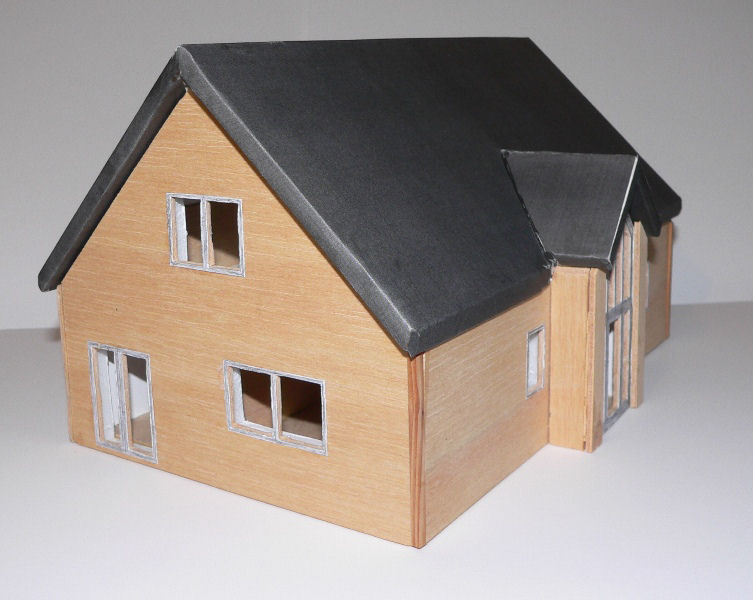
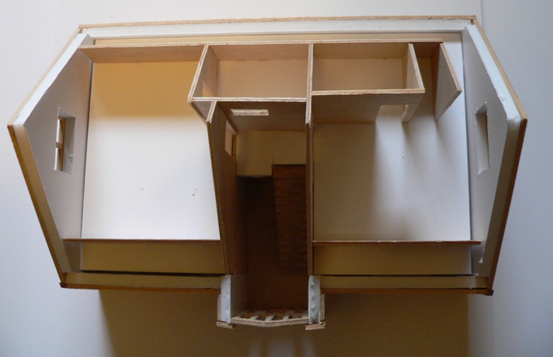
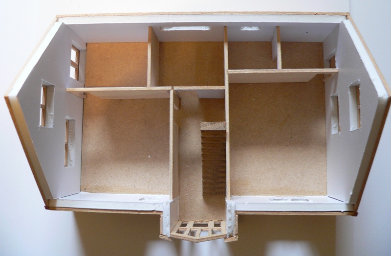
Yes, in fact I built several, all different iterations of the design! The main reason for that one was to easily show people how the house would look in it's setting. I found that a lot of people, particularly some of the neighbours and most of the Parish Council planning committee, were unable to visualise what something would look like from just 2D plans. Because one of the people that was unable to imagine what spaces would be like from plans was my other half, I also made this model, with a lift off roof and first floor, so she could see the scale of the internal rooms. I made this model to a larger scale, 1:50, simply because you can buy cheap plastic models of people at 1:50 that are intended for railway modellers, so I could add people inside the house to get a better idea of the true scale.
- 36 replies
-
- 1
-
-
- planning permission
- planning conditions
- (and 2 more)
-
I'd put OSB on top of the insulation, then GRP on top of that. It's far easier to lay GRP on OSB, and it will bond pretty well to the OSB. making for a much stronger part of the structure.
-
No problem, hope it makes sense. I wrote the original so long ago that I'd have to take a look at it to try and recall what I did! The main issue is that the flow meters indicate velocity, and don't really have an accurate enough flow rate setting (at least the Testo doesn't). That means you need to quickly be able to convert the flow velocity you measure over a specific area (in my case I used a 100mm diameter tube, with a cone to push up against the ceiling terminals) into the flow rate in litres/second.
-
Down the drain! - CCTV, Spurs and Mysteries
Jeremy Harris replied to Ed_MK's topic in Waste & Sewerage
I'm pretty sure that since the changes to the law that forced the water companies to take ownership of shared foul drains, drains that had previously been the responsibility of the householder, they will now not allow you to connect to a shared foul drain under someone else's land, they will insist that you connect to a main sewer, preferably at a manhole. The may allow you to connect to a main sewer where there isn't a manhole, but they will have to be persuaded that it doesn't interfere with the function of the main sewer and that there is adequate rodding access from an access point that is within a set distance from the sewer, as they will take over responsibility for that new lateral as soon as it is completed. -
You can put all four conditions on the same form, that ensures that they only treat it as one request. What I did was very briefly list the pre-commencement conditions, by name and number, on the form, with a note that the evidence showing that these had been discharged was attached. I then attached a document with the evidence. By sending one form, you are cutting off one avenue for them trying to charge you four times. I've attached a PDF of our pre-commencement conditions evidence document that I attached to the form that may help: Planning Condition Discharge.pdf
-
Insulating to Min Building Regs
Jeremy Harris replied to Ian's topic in Energy Efficient & Sustainable Design Concepts
The English standard is the same, if you just meet the minimum fabric standards in Part L1A then the chances are you won't get a "pass" in SAP. It's one of the things that makes it essential to juggle all the various insulation level, airtightness level, fuel type, use of renewables etc around in order to make sure you get an acceptable outcome. -
I think there may be a difference between the different makes of site trouser ones. Being a cheapskate, I bought a couple of pairs of the Screwfix trousers, when they were on offer some time ago. I had the same problem with @joe90 in that the pads were flat and wouldn't bend properly, but also found that the pads were too low, so my knees were just on the very top of them. It probably pays to shop around for ones that best fit your own body geometry, if that's in any way possible (I can just see the reaction in Screwfix if you dropped your cacks to try a pair on................)
-
I'd wholeheartedly agree with @SteamyTea. CFS do some good roofing kits, I've used a lot of their stuff over the years, and for this job I'd be inclined to give them a call for advice. My experience has been that they are very clued up and happy to help, but I'll caveat that by adding that my nephew worked there for years. Here's a link to their roofing section: https://www.cfsnet.co.uk/acatalog/CFS_Catalogue__FLAT_ROOFING_21.html They have some guidance on roofing with GRP here: https://www.cfsnet.co.uk/acatalog/1project-roofs.html but I would be inclined to ask them about your specific requirement, where you're laying concrete on top of the GRP, as the choice of resin may be more critical. I agree with ST that vinyl ester resin would seem to be the best bet.