

Jeremy Harris
-
Posts
26430 -
Joined
-
Last visited
-
Days Won
360
Everything posted by Jeremy Harris
-
 Might have been an idea to foam around the edges before squirting in the slurry, perhaps...............
 -
For us, we saved around £2k in roofing materials plus maybe another £500 in roofing labour by having in-roof PV, so that does alter the cost balance a fair bit in favour of PV, even with the lower FIT rate. The export tariff is index linked, too, and no matter what they do with the FIT it doesn't impact the export payment part.
-
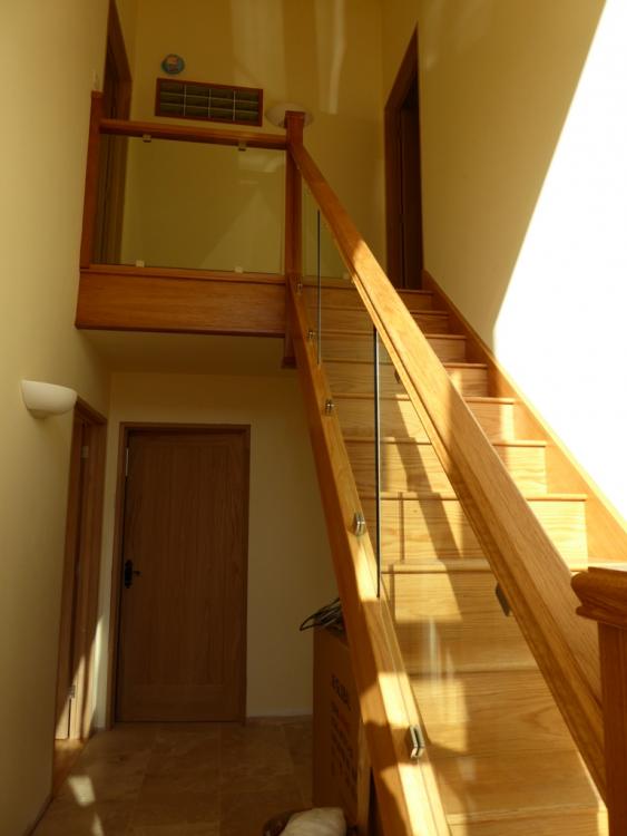
We have the same doors coated with the same product! Excellent, in my view, it's easy to use and gives a nice finish, We also used it on the oak staircase, and it stands up well in terms of wear and tear.
-
There can be advantages in placing a fresh air feed adjacent to a doorway into a room with an extract. For example, I have one in our hall that is above the door to the kitchen and the kitchen is connected to the utility room and then the downstairs WC, so effectively there are three extracts pulling air through that single doorway. By putting a fresh air feed above it, in the hall, I've effectively created an "air curtain" to contain any cooking smells to the kitchen area. You could do the same with an additional fresh air feed above the door to the ensuite.
-
The standard Sunamp PV has an integral thermostatic mixer valve that does just this. You decide on the output temperature you want and just adjust the valve to deliver that temperature, and as long as there is enough charge in the unit to maintain the set temperature it will.
-
There's no intrinsic reason why the extract terminal number has to match the fresh air terminal number, but it does make getting the system balanced easier. The main issue is for the high rate extract case, when the ventilation rate is increased from a bathroom or kitchen in order to remove excess heat/steam etc. That has to be matched by the flow coming in through the fresh air terminals, and with just a single fresh air terminal the flow rate at that terminal could be very high, with the risk that it may be noisy and cause unwanted draughts. If you can make the supply terminal and ducting larger than the extract terminals and ducting then that would help, but if using radial ducting you're limited, because I think that the maximum number of ducts per terminal is two, and that may not be enough to keep the noise down.
-
2 bar static is fine, so one option might be to just fit an accumulator, to boost the flow rate and maintain 2 bar even when water is being drawn off. A gravity system is going to deliver a pressure of less than 1 bar (1 bar ~ 10m head) for most normal height homes, and needs large bore pipework to get an acceptable flow rate.
-
All three of these can use the same immersion heater if you wish. All excess PV energy diverters can be bypassed to turn the heater on when there is no excess PV generation, either manually, with a timer, or both. I fitted a timer with a series switch that I can use to disable the boost in summer as the bypass on our unit, and that originally ran a single immersion heater in the base of our old 210 litre thermal store. The wiring is the same, but we now have it connected to the heating element supply in a Sunamp PV (we removed and sold the big thermal store as it was making the plant room and adjacent bedroom far too hot in summer).
-
Passivhaus training course
Jeremy Harris replied to graeme m's topic in General Self Build & DIY Discussion
That is exactly what I found when looking around for a builder to build our house. It's no accident that our house frame was built in Ireland, that it is fitted with Irish made doors and windows and the foundations and house were installed and erected by Irish guys. For them, building a well-insulated and airtight house to passive house standards was normal, everyday, work. I suspect they may well have felt less at home building a typical UK-type timber frame, TBH. Part of this was driven by the big change in Irish Building Regulations and the way they are applied, following both the disastrous period when really rubbish houses were being thrown up during the boom years, and also because there seems to be more emphasis on energy efficiency, which may have a fair bit to do with natural resources and pressure to reduce things like peat-burning power stations.- 11 replies
-
- 1
-

-
- passive
- passivhaus
- (and 2 more)
-
another expensive extension to policy
Jeremy Harris replied to lizzie's topic in Self Build Insurance
That was my experience, too, which is why I ended up ringing around and finding a broker that could get an insurer to provide appropriate cover. What we actually got was a modified version of an insurance policy for major restoration works, that included all the required re-building cost cover plus a load of other stuff, but allowed for the building to be unoccupied for periods. The only stipulation was that the building had to be secure and weathertight. -
How much to insall a sewage treatment plant?
Jeremy Harris replied to vivienz's topic in General Construction Issues
I've just checked our ground works cost breakdown. We bought the treatment plant, which was £2200, but that price was because we needed a pumped outlet. IIRC, the basic model with gravity drainage was around £1800. Our ground works guy charged us £850 to install it, but that includes digging a trench across a lane for the pumped outlet, as well as digging the hole and "planting" the thing properly in it (we went for a concrete ring ground anchor, just in case the water table came up when the thing was being emptied). So all in, purchase and installation should cost around £3k I would have thought, especially if you don't have to trench under highways. Those costs reflect the facts that we already had diggers on site for the main works on site and that I had already paid a highways licence to dig across the lane for a power cable duct (the duct and the treatment plant outlet were both put in on the same day). If you need an extensive leach field system to be put in place for the land drains, then you may incur additional cost, depending on how big this needs to be. We had no room for a leach field and the soil was impermeable anyway, so we pump ours out to the stream alongside the lane. -
another expensive extension to policy
Jeremy Harris replied to lizzie's topic in Self Build Insurance
When faced with an extortionate demand for an extension to our site insurance, I found a broker who went through exactly what sort of cover we really needed. As there was no more "building site" as such, no scaffolding and none of the outdoor risks normally associated with building (diggers, other plant moving around etc), and as the house and garage was secure and almost complete, they found an insurer who was prepared to provide unoccupied buildings cover that met our needs and was around 1/3rd the cost of a normal site policy. I took great delight in telling Buildstore to stuff it. Their fees are so extortionate that I'm surprised no one has come along to seriously undercut them, as they don't seem to add any more value than a good broker. -
Kingspan heating (or lack of) issue
Jeremy Harris replied to Lynford's topic in Air Source Heat Pumps (ASHP)
The heating circulating pump will come on, as will the heat pump, even if the valve is jammed. The pump and the valve are controlled by relays inside the heat pump. As long as terminals 13 and 15 are open circuit, and as long as terminals 3 and 6 are closed, the heat pump will run in heating mode and the circulating pump will come on. -
Kingspan heating (or lack of) issue
Jeremy Harris replied to Lynford's topic in Air Source Heat Pumps (ASHP)
As a couple of further points, the heat pump has internal 230V AC relays that are used normally to switch on the heating circulation pump and operate the three way valve, to select between heating and hot water. The heat pump will turn on in hot water mode if terminals 13 and 15 are connected, via the programmer and tank thermostat. When the heat pump switches to hot water mode, the circulation pump for the heating will probably be turned off and the motorised valve should switch to the hot water position. If you look at the wiring diagram in the manual, on page 19, you can see that there are another set of no-volt switches connected to terminals 13 and 15, the tank thermostat and programmer, which look to be wired in series. This means that in order to get hot water, both the time switch contacts must be closed and the tank thermostat contacts must be closed. Hot water mode over-rides heating mode completely, so if the unit is being asked to deliver hot water it won't run the heating. Worth checking those as well - they are no-volt connections, so should be a maximum of 12 V. The operating sequence in heating mode is that the room thermostat calls for heat (the contacts close that should be connected to terminals 3 and 6) and as long as there is not a call for hot water (in other words either, or both, the timer or the tank thermostat contacts are open) then the heat pump should turn on the circulating pump, ensure that the motorised valve is in the heating position and then the heat pumps should start running. It has a slow ramp up, and takes around 30 seconds to start up, as it has a designed in soft start. -
Kingspan heating (or lack of) issue
Jeremy Harris replied to Lynford's topic in Air Source Heat Pumps (ASHP)
The unit needs a switch that is not connected electrically to anything else wired between terminals 3 and 6 on the heat pump unit to turn it on. In order for the heat pump to operate in heating (rather than cooling) mode terminals 3 and 7 must be bridged too. These terminal numbers refer to the terminal block outside in the heat pump. They are at 12V on an isolated supply, so just a switch across 3 and 6 will turn the heat pump on and off. Often there will be a microswitch on a motorised valve that operates when the valve moves and can be used to turn on the heating. If it is wired as per the diagram in the manual, then terminals 3 and 6 should be wired directly to the thermostat and the thermostat then turns the heat pump on and off. According to that diagram, the thermostat is the only on/off control for the heat pump. You should be able to check whether or not it turns the heat pump on and off by adjusting the thermostat temperature upwards and seeing if the heat pump comes on. You will probably hear a click in the thermostat as it goes above the set point. If you hear the thermostat operate, but the heat pump does not turn on, then that indicates a problem somewhere with the low voltage wiring between the thermostat and the external unit. You can bypass the thermostat (with the external cover of the heat pump removed, (bearing in mind the caution about there being live connections exposed) by connecting a bit of wire between terminals 3 and 6, making sure terminals 3 and 7 are linked. Doing this is safe, as those terminals only have at most 12 V on them, -
I wholeheartedly agree with @jamiehamy, although in my case the procrastination ALWAYS involves clearing up! I ended up with so much crap lying around that I just can't really get on with anything, and then put off having a major clear up session. I spent much of yesterday clearing up and putting stuff away to make room to finish off my study, and feel a great deal better for it. I really wish I could get into the habit of clearing up at the end of each day, but I can't, I just want to get a bit more done, and that then leaves no time for a clear up................
-
You still have to overcome the switch certification problem when run on DC. I spoke at length with MK and they were adamant that their range of AC switches were not suitable for use on DC and could not give a derating factor. Now I know people have used ordinary wall switches to switch DC, on boats etc, but the remains a problem with a house, where any fault could result in serious consequences, and may well impact on insurance cover. I've no doubt that most of these switches would probably handle maybe 1/3rd of their rated AC current when used with DC, but their life may well be reduced because of arcing caused by their slow break characteristic. My proposed solution was to fit DC relays, with fast acting, DC rated, contacts up in the ceiling void, switched by a very low DC current through the wall switch, with a snubber across it to reduce the risk of problems from switching the inductive load of the relay.
-
All the many MR16 samples I obtained just used an array of series/parallel connected LEDs to get close to 12V, plus a bridge rectifier (because the 12 V downlighter spec is 12 VAC) and a very low value dropper resistor. There were small losses across the resistor and diode Vf in the rectifier, but these were modest, and little more than a cheap switched mode regulator. They were free of any interference generating elements, too. IIRC, the Vf of the white LED varied from around 3V to 3.3 V (with current and colour temperature), and they were wired in banks of three in series, giving 9 to 9.9 V to drive them. The bridge rectifier included two diode Vfs of around 0.6 to 0.7 V each, so increasing the voltage required to around 10.2 V to 11.3 V. The LEDs were run at between 20 and 30 mA, so the dropper resistor only had to lose between 1.8V to 0.7V. It's not the most efficient system, but the total losses aren't that far off those for a typical cheap switched mode supply. One thing I did find was that the multiple 5050 LED MR16s were not happy when driven with the small "electronic transformers" intended for normal halogen MR16s. The reason was that these put out 12 VAC at around 20 kHz, and the bridge rectifiers in the MR16 LEDs weren't capable of switching that fast, as they didn't use fast recovery diodes. The result was that they overheated and would eventually either smoke or unsolder the SMT bridge rectifier from behind the circuit board. Running the same LEDs on 12V DC fixed the problem, and they barely run warm.
-
Oh the irony: the annoying irony
Jeremy Harris replied to ToughButterCup's topic in Electrics - Kitchen & Bathroom
Our first cottage, which was originally just a two up, two down stone built terraced cottage, built in the 1870s, still had the central walls either side of the stairs like this. There were T&G boards on one side of the studs with the other side left open. The open side faced the rooms, for some odd reason, and had layer upon layer of black varnish. I ended up plaster boarding it all over. -
There are some decent, metal encased, switched mode supplies, with decent filtering, that are not too expensive. They are all made in China, but I've found that the supplies sold by LED Hut ( https://www.ledhut.co.uk/drivers-fittings-switches.html ) tend to be pretty good.
-
That's interesting. I binned our MR16 fittings and replaced them with flat panel LEDs, run from a decent DC supply, and it made a big difference, but I'm wondering if part of that difference may be that I did make sure that the 0V side was connected to earth, so I have now earthed all the cases of these LEDs. It could be that's what made much of the difference. The snag is that wall switches are not designed to switch DC at all, as they have really slow to operate contacts. You may well get away with one running a very tiny load, like 4 off 3W LEDs, but you will need a lot more LEDs than that to light a room well, especially a kitchen or utility room. I have a total of 48 W of LED ceiling panels in our kitchen, and that's marginal, in my view. I had to add supplementary LED strips under the wall units to get an adequate light level on the worksurfaces, and they add an addition load of around 12 W, so if I'd used 12V DC switched supplies then the wall switch would have been handling a total of around 60 W, or 5 A. I doubt the switch would last long switching 5 A DC, but more importantly, it has no certification for use at DC, which could cause problems in the event of something going wrong. The other problem is the vampire load from the power supply. Even a really good switched mode supply may draw around 5% or so of it's rated power just when powered on with no load. Add that up for 24v hours a day, 7 days a week, and it's apparent that it's quite a bit of wasted power, especially if the supply is rated for the whole house, or even just a single floor in the house.
-
A better arrangement might be to fit the float switch that turns the pump off when the rainwater tank is empty in the rainwater tank itself. You can get three wire float switches, like this one: http://www.wiltec.de/float-switch-pump-level-controller-cable-5m.html?currency=GBP that can be wired to turn the pump power off when the rainwater tank is empty.
-
Very, very, true. I had to do a lot of work replacing very noisy ones that completely blanked any radio in the house. There is some real rubbish stuff around, and unfortunately it's not easy to sift the good from the bad without buying some and trying them. I ended up replacing all the 230 VAC LED constant current supplies that came with all our kitchen ceiling lights, because of the electrical noise they created.
-
MBC and attaching things to walls
Jeremy Harris replied to vivienz's topic in General Construction Issues
Yes, I'm sure. I have pipes and cables running through the ceiling void and dropping down into the wall service void all over the place, with no battens in the way. It's handy, as I've retrospectively run some ethernet and speaker cables down the wall service void from the eaves space.. -
Cable size, voltage drops and a lack of DC capable switches is the simple answer. I was going to do this, but no one makes a DC rated wall switch, and none of the wall switch suppliers would tell me what sort of current they would take at DC. My best guess is that they would need to be de-rated to around 1/3 to 1/2 their AC rating (that's a pretty normal sort of derating for DC switching) and then none of the readily available switches will handle more than a few LEDs, certainly not enough for a room. I did look at using a bank of relays to switch the 12V DC, so the switch current would be low and within the likely switch DC rating, but it all got too much hassle, so I ended up using separate 12V switched mode power supplies switched by normal 230V AC lighting circuits.

