Leaderboard


Popular Content
Showing content with the highest reputation on 10/10/23 in all areas
-
So I managed to core my three 152mm holes. I purchased a Makita 8406 core drill, which is capable of dry coring upto 152mm and it did them with ease. I figured I'll add it here as it may benefit someone else at a later date. I paid £240 for the drill, ok so I could've hired a drill for half the price but I still have a few more smaller holes to core and so it will certainly come in hand in the future. Thanks to all for the comments.3 points
-
i'm going to heed @Nickfromwales's advice here and go brass. it also just feels right to be threading a brass thread into a brass socket. going in to plastic just feels wrong!2 points
-
In my topic Modelling the "Chunk" Heating of a Passive Slab, I discussed how I used a heat flow model to predict how my MBC WarmSlab heated by UFH + Willis heater would perform. What I wanted to do in this post is to provide a “6 years on” retrospective of how the house and slab have performed as built based on actual data that I’ve logged during this period, and to provide some general conclusions. In this, I assumed 15 mm UFH pipework, but we actually used 16mm PEX-Al-PEX pipework with an internal diameter of ~13mm. At a nominal flow rate of 1 m/s, say, my three pipe loops in parallel have an aggregate flow rate of 0.4l/s or 1.4 m³/hr. At this flow, a 3kW (2.88 kW measured) heater will raise this stream temperature by 1.7 °C. However, when I commissioned the system, I found setting the Gunfoss manifold pump at a high setting (roughly equivalent to this flow rate) gave a very noticeable circulation noise in the adjacent toilet, so I tried the pump on its lower settings and found that the flow was almost inaudible on lowest one with in to return delta at the manifold still only about 5°C, so I stayed with this. The actual as measured delta for two loops of 4.9°C and the third slightly shorter loop of 4.1°C (close enough not to bother balancing the flows out). This corresponds to an actual flow nearer to 0.4 m/s or 0.56 m³/hr by volume. When scaled to adjust for this lower flow rate, the actual measured temperature profiles are pretty close to those modelled. I measured the actual Willis heater’s heat input as 2.88kW. In analysing the actual slab heating rates, I found that this raises the overall slab temperature by some 0.45 °C / hour after the initial start up. Plugging typical specific heat and density figures for the concrete, this is empirically equivalent to heating 25 tonne of concrete (Cmass = Ewillis/ΔT/SIconcrete = 2.88*3600/0.45/0.9 kg), or 10.6 m³ concrete by volume (23000/2400 m³). In the case where the Willis provides heating for the full 7 hour off-peak window (just over 20 kWh), at the end of this heating period the flow input to the slab is +9 °C above the initial slab temperature and the flow return is +4.4 °C. The temperature of the concrete immediately in contact with the pipe will follow this same gradient, with this temperature excess decaying radially away from the pipe centres. By the end of this heating window at the slab surface, there is barely a noticeable difference in the measured temperature of the floor above the out and return UFH pipe runs (perhaps 1°C). These temperatures and gradients are also comfortably within the reinforced concrete’s design parameters. As soon as the Willis is turned off, the internal temperature gradients start to flatten and any unevenness redistributed across the slab; the rebar reinforcing has a thermal conductivity 60 × that of concrete and this accelerates this, so that within an hour or so of the heating turning off, the overall slab is left about 3.1 °C warmer than at the heating start time (actually about 10% less than this, as the slab has already started to dump heat into airspace). In my original modelling topic, I mentioned that my passive slab has ~73m² of concrete 0.1m thick (~ 17½ tonne of concrete with another ~10 tonne of perimeter beams, cross bracing and steel rebar, with the UFH runs laid in 3 × ~100m long standard “doubled back” spirals (common to most UFH designs) on ~150mm centres and roughly 50 mm below the slab surface. (Actually only 75% of the slab is covered by the UFH runs, because of the need to avoid proximity to ring beams, partition walls, areas under fitted cupboard areas, etc..) Nonetheless, this empirical 25 tonne figure is still consistent with the total volumetric 27½ total estimate if we assume that the rebar is effective at spreading heat through the wider slab over this multiple hour timescale. In conclusion, based on this modelling and observation: First recall our context: our house is near passive in class with a lot of internal specific heat capacity. We only need about 1kW overall heater input in the coldest winter months to maintain overall heat balance, e.g. either by a resistive heater such as a Willis or an ASHP. IMO, there are two extreme approaches to house heating: (i) “agile” tracking of occupancy patterns so the living spaces are only heated when and where occupied; (ii) a 24×7 constant comfortable temperature everywhere within the living space. Our warm slab design is very much optimised for this second case, and our slab supplier did a good job in designing an UFH layout to match the slab characteristics to this The slab is covered in “doubled back” spirals with each loop using up a full 100m roll spaced on roughly 150 - 200 centres (and avoiding partition walls and cupboarded areas) so that each heats roughly 15 - 20 m² slab. In our case three loops were enough, and there was no advantage in trying to squeeze in a fourth. Our 3 loops will happily take up 3 kW heat input. Circulation speeds between ⅓ - 1 m/s seem to work well, with the only real difference being the slower the flow speed, the higher the delta between in and return temperatures. The slab does just as its trade name suggests: it can be treated as a huge low temperature thermal store, but because of its extremely high thermal inertia, one that is not rapidly responsive to heat input. In our case, a heat input of 3 kW input will only raise the slab temperature by 1°C over a couple of hours, and radiating 1kW will drop the slab by only 1°C over roughly six hours. In a true passive class house, one key to heating economy is the high level of thermal insulation coupled with a substantial internal heat capacity. Trying to drive such a house in an agile manner is a fruitless exercise, so forget the traditional having room-specific thermostat control; forget having traditional time-of-day heat profiles. It is far easier to treat all ground-floor rooms as a single thermal zone to be kept at a roughly constant temperature. In my view, using a resistive heating approach (such as a Wills heater) as well as an ASHP can both work well. In this second case something like the 5kW Panasonic Aquarea ASHP would be a good fit as it uses a modulated inverter compressor so it can heat the slab directly without needing a buffer tank. The choice is a trade-off between running costs vs. installation costs. In our case, switching from a Willis to this type of ASHP would save me about £600 p.a, in electricity cost, so I would really need to do the install for a net £ 3-4K to make the investment case feasible. However I would like to defer this discussion to a separate thread because there are other issues that such an approach would need to address.1 point
-
Hi All Joined to comment on a thread I found whilst searching the interweb but seeing as an introduction is required thought I'd throw a bit of background down Current house owned 33 years but updated over the years 1980's built detached 4 bed so originally open cavity walls, 25mm of loose fill loft insulation, single glazed doors and windows, void floor downstairs over a 2 - 3 ft crawl space and back in 1991 an annual gas usage for CH and HW of 25,000 kWh two floors with a total of 113 m2 (Small extension done in 2006 to building regs at the time) have reduced over the years with Double Gazing, Cavity wall insulation, upgraded loft insulation (could still be better), new boiler and replacement rads and spent 3 months last year doing 56m2 of 75mm PIR between the joists under the ground floor - amazing reduction to heat loss considering heat is supposed to rise 😉 Currently 8500 kWh gas usage per year for CH and HW but looking to use it more effectively rather than reduce it further1 point
-
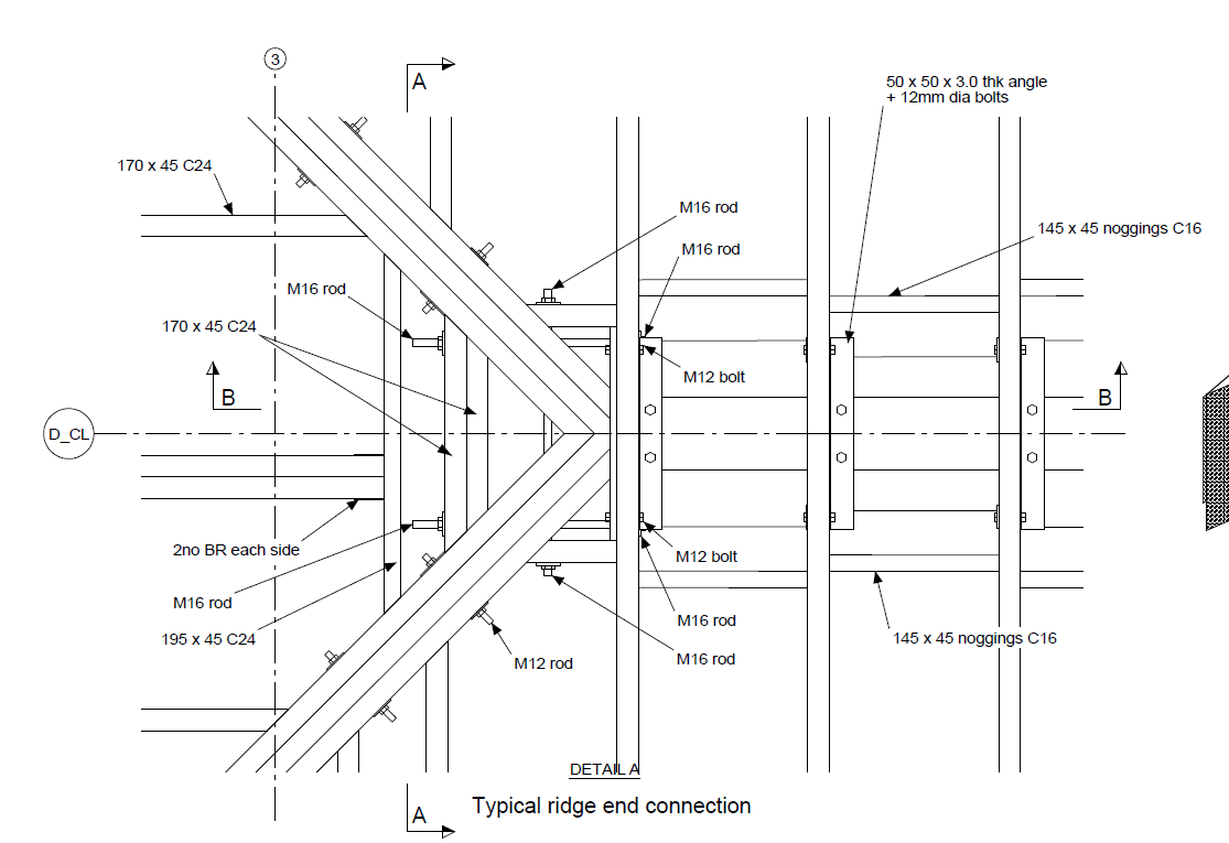
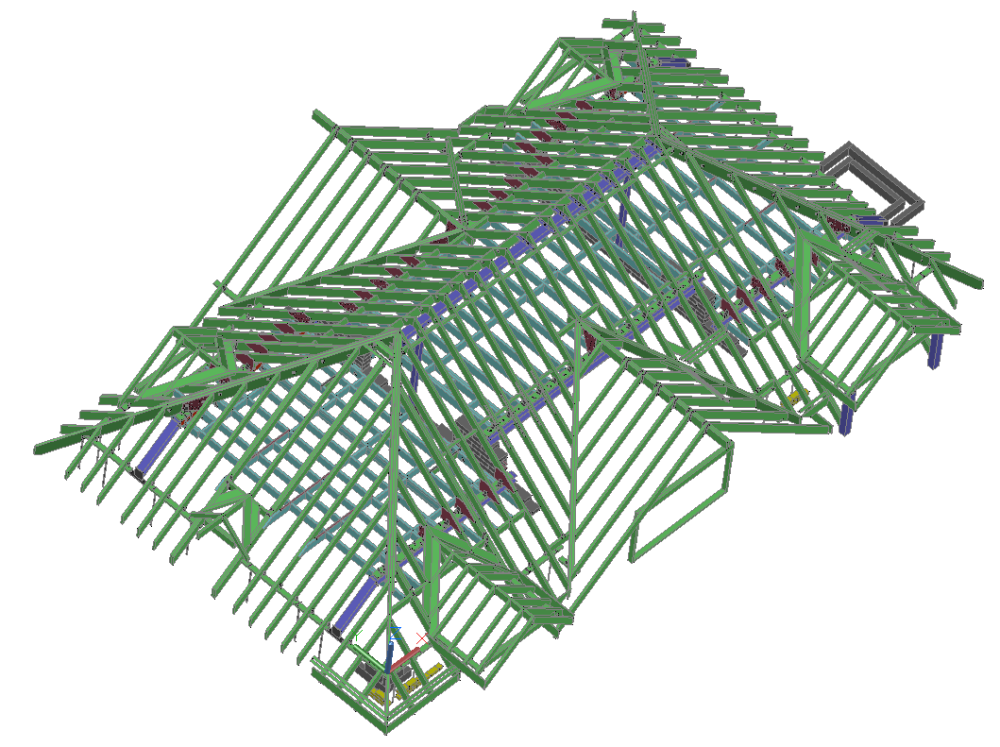
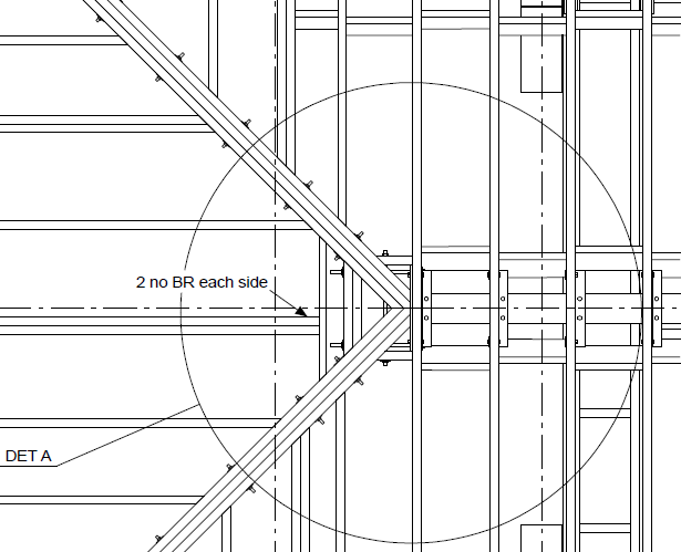
Can see the general thrust of the design, some steels etc. I have not studied in detail but pick out one element.. the roof. You have flitch beams at the roof hips. That is going to be more expensive once you detail that up and realise how difficult that is for a normal builder to put together and build properly. The following is pretty detailed but I hope it gives you food for though in the sense that you need to ask a lot of questions and try and look at the design holistically In other words if we buy a motor bike in parts the sum of the parts will cost more than just buying.. ready to ride away! Below is screen shot of my structural model of a roof I got involved in and improved / value engineered. It's possibly more complex than yours but there is a lot in it that may help you get your head round what is coming down the pipe. The first screen shot is of the overall roof structure. I can see that on your roof plan at the bottom you have some heavier, treble rafters.. I'm guessing this is for a big roof opening / dormer? At he bottom left of the model there is a dormer, a bit smaller than yours but the concept is the same. The main thing about this model is that all the parts are off the shelf, nothing hard to source and a decent builder will be familar with working with the different components and know how they are supposed to be installed. The aim is to go for the simple stupid. Lastly all roofs are different ( the layout and support positions below also drives the roof model) when we get into the fun part of self building so don't take my way as the best way for your project. Below is how I swapped out the originally hip flitch beams for solid timbers and the hips.. they are offset in the vertical direction but I gave the builder the info they need to offset, rather than just guessing. It's actually quite easy to do once you get your head round the roof angles and if you can do a compound cut (a competant joiner/ chippy should be able to do this easily). I know as I used to be on the tools before I was an SE) In the above there are short horizontal timbers with long threaded rods (from Jewson ect). These tie the hips together and back into the main roof. You can see there is no connection at the ends of the hips to the ridge area aNd may wonder how the vertical downwards loads are resisted.. The reason for this is that in practice with the steel between the timbers the connection is so complex it almost stops working. Ask you SE how the are going to detail the flitch beam to ridge connection. Would be interested to see how they do it. For me I'm sharing what I know and how I try and simplify so in the round we stand the best chance of getting it built the we want without costing a fortune. The above is a screen shot looking up from below. Here I cantilevered the ridge beam so we have a simple connection between the supporting post and the ridge beam. Let's break down big problems and make them into simple things that can be tackled one at a time on self builds. The ridge beam has an big steel angle shop welded onto the end.. now we have big ledge to support the hips.. the chippies / joiners can't miss that landing area, even if they cock it up a bit there is some slack in the design. In summary the two images above show how I tie the roof together and support the vertical loads by decoupling the hard things to do on site.. Below are some screenshots to show how the model gets translated into a "paper drawing" for the builder. Incedentally if I'm doing something like this I always give the builder the 3D view and say.. I want it to look just like that! It's also great for self builders (and me) as its helps you visualise what needs done.. and it is great fun! Below there are a few things / ways where you can save money and some food for thought. When we are working with steels supporting roofs the steels themselves are usually not that heavily loaded to the extent that the steel material wil start to fail. Normally as steel is "bendy" it's the deflection that govens the design. This often means that the connections can be made more cheaply in a domestic application. You may see some SE's asking for a "full strength connection. This can involve an expensive welding process and beam end preparation. If the connection forces are relatively low then we can often use what is called a division plate with a bog standard 6.0mm fillet weld. The plate is cut from a bog standard flat bar.. off the shelf. Below shows a cranked beam form the model with a division plate shown as the black bit between the beams. Here we just use standard 6.0mm fillet welds to join it all together. Cheep and chearfull. I did check the division plates would not stick out the roof by the way!. In the above you can see a timber wall plate bolted to the top of the steels. It can also often be shot fired.. ask your build what preferance they have. In this case all the steels came predrilled to make it idiot proof.. I said if there is a hole it needs a bolt. The red bits are plywood gusset plates nailed and glued to the sides of the rafters, there is a timber packer behind these gusset plates you can't see. The reason for this is partly geometric and partly govenernd buy the Architectural design. But in essence this worked on this job to transfer the roof loads down onto the steels while also tying everything together. The L shape brackets are just Simpson or similar stuff off the shelf. Hope this post helps inspire..


 1 point
 -
Quick update, fired a few question over to natural green heat and got a reply almost instantly so ordered the system (duct and plenums) Shortly after ordering got a call from them explaining how the Heatpex system goes together and confirming it’s all ready to be shipped! I can’t remember the chaps name who I spoke to but he was extremely knowledgeable on the product, gave me the company backstory and I’m glad jayc89 put me onto them👍 For anyone contemplating 75mm or 95mm ducting pick up the phone to them for some good honest advice. Companies like this are rare so we have to keep them going🫡1 point
-
Oh that’s me too!!!, however I find it’s what it looks like to the eye, a wonky wall against a straight one will be noticeable, 20mm is not too bad over the length but it depends on how OCD you are, if like me you will “see it” every time you go past then feather it out for a peaceful future life.1 point
-
Round to rectangular are stocked at TS and SF.1 point
-
How old is the building? I'm a bit fascinated by the way we (me too) instinctively want things plumb and square and at-the-same time love the out-of-shape quirkiness of old buildings, old furniture and old industrial artifacts. I'm not being facetious - is there any chance that in 10, 50 or 100 years someone will think how wonderfully quirky and full of life that out-of-square wall will be?1 point
-
I think the key to stopping it rotting is to keep it off the ground with a post base as @joe90 suggests. On some oak posts I made my own from 12mm SS threaded rod, plates and nuts but I didn't have to worry about wind lifting the post off the rod. If really keen recess the bottom of the post to make a "drip groove".1 point
-
You can always use a bureau e.g. 3dprintuk - more expensive but zero faff. Great for small stuff - the price is generally based on build volume.1 point
-
Probably between 10 and 12 years ago. They went bankrupt when the government (greenest government ever under Cameron) pulled the plug on the grant system.1 point
-
I have always wondered why this is not a standard practice. And why do a lot of windows designs stop replacement glazing being fitted from the inside. Looks a very similar system to what the Mark Group were fitting a few years back.1 point
-
How big is the volume it is entering, will there be furniture in the way? Can you distribute the inlet into 2 or 3 in a line? Or is the 733 lt/s (0.92 kg/s) the total airflow for the whole building? The kinetic energy, is very small, so would not think it is noticeable.1 point
-
Then you jack up the shed and slide the 7N in their place1 point
-
We put up posts and strung a thick rope between them using brass fittings. Looked nice, didn't really obscure the view and did the job. Just whip the rope ends to look nice.1 point
-
Check the spec for whatever multifoil you have in mind, as there may be battens required for air-gaps either side, so thin might = 'fat' after all.1 point
-
hey. thanks for the info. I've made a decision and I am using copper push fit wall plate elbows. only time will tell if it's the right thing to do! I'm gutted I can't find/Wavin don't sell the brass Hep2o wall plates any more as that would've been my preferred route. I'm sure it'll be fine. 🤞1 point
-
The field and road runoff is designed to run into the ditch on the opposite side of the road. There’s a trail path opposite the neighbour’s house just up from us. The water cascades down this in heavy persistent rain. 90% of the time it runs into the ditch the trail crosses. Under heavy downpours it overflows runs towards his house. Historically I assume he’s just cut into our plot when it was a field and decided to do it again despite it no longer being a field. All he really had to do was put a few sand bags across a small part of the trail where it joins the road and it would have pushed it back into the ditch. I’ll talk to him about it the next time he visits (it’s a holiday home) and come up with a permanent solution.1 point
-
+1 The more cash you have, the less you will fret. You will already have enough to worry about.1 point
-
What I meant in times gone by pb a shower enclosure and then simply tiling over it . Slightest of grout failure and the pb soaks up the water and the wall becomes unstable .1 point
-
Drugs are not the answer! 😤1 point
-
You'll not go far wrong in following Octopus's trial process for accepting non MCS systems onto there export tariffs. They are asking for proof that the roof can take the load by way of building control sign off, and an electrical installation test cert.1 point
-
@Thorfun Morning pal, I've had a sleepless night trying to figure a solution to this conundrum! I came up with the conclusion that there is a solution but they all require more joints 😕! This is from a discussion on one of @MortarThePoint posts where the question was asked what the best way to bring hep out of the wall. May help. It may be easier to use a shower fitting even for a basin etc: https://www.ebay.co.uk/itm/322273391778 And a couple of hep2o adapters: https://www.screwfix.com/p/hep2o-plastic-push-fit-adapting-male-coupler-15mm-x-1-2-/5970f As that gives you more meat to screw to the wall. At the expense of more joints.1 point
-
If you contact Wavin and tell them you’re fitting a 400mm lever in to it they may say ‘behave’ and dissuade you from using them. They’re for taps / close to wall items where they won’t come under undue forces etc. Brass here, all day long mate!!1 point
-
Yup. Likewise lol.1 point
-
I would hold on to your cash Lije with most things It’s better to have it and not need it1 point
-
Superfoil is ideal for this From memory = to 60 mil of pir1 point
-
There will be a way of doing it from the inside. A reciprocating saw is your friend.1 point
-
As for software... I'm liking the free Personal/non commercial version of Fusion 360. You can export from that to any of the slicer programs. I'm using Cura which works but there might be better slicers out there. My printer was an ultra cheap A8 kit since heavily modified. Great for learning and experimenting but if starting over I'd buy something better with auto bed levelling. One other thing mine can't do is pause and resume a print. It crashes if you try. That means I have to be sure I have enough filament left as I can't pause to load a new spool. Also can't pause to drop in a captive nut and print over the top of it.1 point
-
You should be able to, but a lot will depend on how the window and the EWI 'interact', and whether the window originally went in from the inside or from outside. Worst-case scenario could be that the inner lintel obstructs the frame coming out inwards, but I think that's unlikely. Even if you had to cut the frame out in bits you could do so with little damage to the EWI with, say, careful use of a reciprocating saw.1 point
-
I've got 6 runs in operation. 3 are on mains with timers and 3 are solar pumps from barrels. All are tube and dripper systems. All very fallible due to variously. Tubes popping off droppers and connectors. Cats or other creatures pulling them apart. Muck in the droppers. Increased water pressure breaking the connections. Reduced water pressure so drippers not functioning. Battery failure. Valve failure. An underground pipe would add to these problems, or simply hide them. I leave my plants in their care when away, but wouldn't assume all will be well. The watering can is still very well used. My grass never gets watered. Doesn't need it, as I don't play croquet. Roses and most garden plants, rven vegetables only need watering about twice p/a.1 point
-
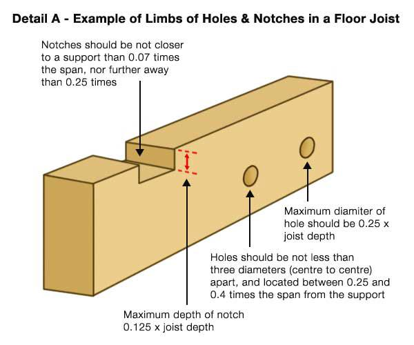
I doubt they can blanket approve something like this as too many variables. I suppose it's upto your BCO to approve it and they might want to see the design justified by a SE to cover their backside. Normally joists are sized to allow some holes without reinforcement. These should be on the vertical centre line and a diameter no more than a quarter of the joist height. There is also a limit of where they can be along the joist. Not sure if these are the latest rules.. https://www.diydoctor.org.uk/projects/Notching_joist.htm
 1 point
 -
I’m not sure where you are but highways where consulted on both our builds Existing access being used1 point
-
I have experience of this, feel free to PM me if need be.1 point
-
The top soil / made up ground will have inconsistent ground bearing pressures across the footprint of the deck. Hence if you use pads that aren't footed on the virgin clay, then you should expect some degree of differential settlement across the pads, and some buckling of the deck in consequence. Pavers are a bad idea for pads unless you correctly load spread and the posts will tend to break them up and punch through them. The method shown in that Wickes video is about the simplest. The holes really just need to go down to the virgin clay, which might only be 30cm or so, but you won't know until you've dug a few out.1 point
-
So.. Set the bottom and the front of the stairs square? Gain the extra 20mm as you climb and rely on alcohol to avoid the stress of it? Or render and feather?0 points
-
@Crofter I am taking a keen interest in what you are doing. For many years now I have thought that directly heating the air is the better way to heat a space, the downside has been that most of the systems available are US systems, so generally oversized. There is an argument to be made that UFH is better, but there are downsides to it i.e. heat loss to ground, fixed position, repairs may be expensive. There are problems with air handling, main ones I see are the size of ductwork, flowrates and limited temperature, and then the big one, sound transmission between spaces. When I was a kid, our neighbours has a hot air system, and it was almost as good as an intercom system for attracting attention. I can imagine a drunken conversation where one half hears everything from another room. Would probably end badly.0 points
-
I used flexible tile adhesive. I would think that bit of flexibility would help . Assume it’s a solid e.g stone tray ?0 points