
Leaderboard


Popular Content
Showing content with the highest reputation on 02/08/24 in all areas
-
Not tried warmup, tried a couple others and they've been 💩, I trust this forum more than the wider world.2 points
-
For me, that would have to go, and I don't care what it cost the installers to correct.2 points
-
You will need to use a fair face block which doesn’t have all the little dimples in it, painting onto standard concrete blocks will give it the appearance of a cheap garage. the time you have paid the extra for the blocks and the paint and painted it you could have had it rendered.1 point
-
Printed the jpg as PDF, opened the PDF in 'PDF Xchange editor' which allows you to add dimensions, i changed the scale of the dimension too to match those on the drawings then added more dimensions using that 'custom' scale.1 point
-
https://www.iflscience.com/deep-abandoned-mine-in-finland-to-be-turned-into-a-giant-gravity-battery-72835 ...It should be capable of storing 2 megawatts of energy.1 point
-
I was being a wally, making more complicated than it needed to be, I'll just run the cables through the wall, then crimp some rj45 plugs.1 point
-
Are you seeing 2 zones on the controller per my earlier image Are you seeing 2 zones on the main controller now? If not SW2-7 may need to be moved to on and maybe SW3-6 as well the manual isn't the clearest. Don't forget to power it down before any changes otherwise they won't take effect
 1 point
 -
thank you all for your help. I have sent them an email, sent all the pictures and measurements and let’s see what they say. will keep you posted.1 point
-
No. But you are shouting into the cavernous mouth of a massive deaf volcano. On-the-job tidiness is for others - the site cleaner, the apprentice, the owner, the wife (yes I know - but it's true). MDF has a carcinogenic edge to it, the greater the urgency therefore. Have a look at Peter Millard's YT channel. He works (used to? ) with MDF a good deal. Tidy to a fault, excellent carpenter, but suffers from some sort of bronchial problem. Hence his attention to dust reduction. One of his videos is about how on-the-job tidiness gets him a good deal of repeat business. 'Nuff said.1 point
-
check very carefully the document you signed, as if by signing you have accepted any liability of the measurements. However comment sense is that the surveyor is responsible, as even if you accepted liability by signing it, then you can go after the surveyor who has been negligent and not done their job properly.1 point
-
i originally thought that some of the liability was with you, however i have changed my mind and its all on the surveyor, he made the mistake, having a surveyor is the person to measure up. Check what you signed and see what the wording is about measurements and responsivity. As by signing the document you may have taken in liability for the measurements. I have added some measurements to yours calibrated to the ones on there already.
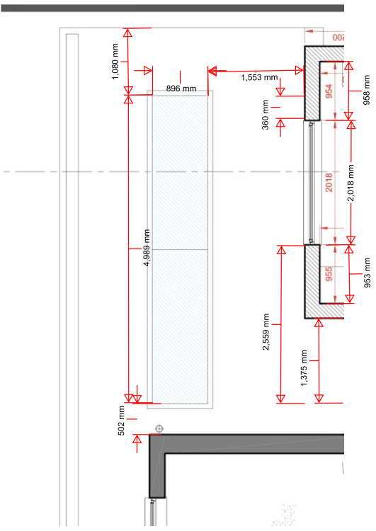 1 point
 -
The Posi design included a tolerance gap below the Top Chord. This was not requested by me, but I ended up utilising it to deal with any clashes of Ledger fixings. I was able to plan the fixings to miss the Posi positions until I got half way along, where there was an irregular gap due to an internal wall position, but it didn't really matter. I planned the MVHR exhaust and inlet to fall within a 300mm gap between 2 Posis. These went through before the concrete and ended up as I intended. There is another of these on the opposing wall. They both head towards each other, the drop down into the plant room, either side of the Strongback, which doesn't interfere. I'm planning to infill between the joists with 47x50mm CLS, which I will cut to 300mm lengths to help me space the joists consistently. How should I fix the Posis to the Ledger? I'm thinking 2no 5x80mm screws in each, predrilled downwards through the top chord into the Ledger?
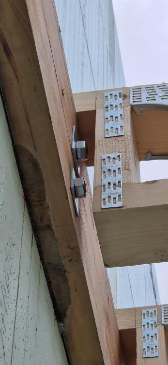
 1 point
 -
1 point
-
Yes MDF dust gets everywhere and yes he should have done it outside so give him a bollocking but at least he has done a good job, if it were the other way around it would be more annoying (work done outside but shite workmanship) 🤷♂️1 point
-
They need to be on IN-1 for single zone operation, that's where my UH8 is wired to, so Lr and Ls need to go to IN-1
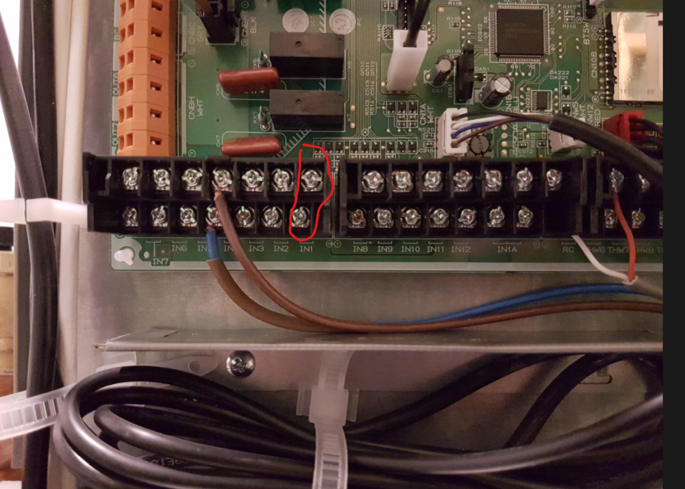 1 point
 -
I would grab a chainsaw and cut every single one of those joist out. fix a ledger board around the whole perimeter of the blockwork, fixed using resin anchors with a mesh sleeve into the holes to allow for the dodgy blocks. then fit new metal web joists to the whole area. far easier to get all your new services in, will be flat and level. all depends on how far you want to go. or alternatively remove all services. cut existing joists out from the pockets in the wall, fit a ledger board along that wall and fit the old joist to the new ledger board with hangers, changing the spacing to 400centres, add new joists to make up the short fall. or something like that.1 point
-
Just to clarify my answer above was for terminal ends, with a single cable. For daisy chain intermediate nodes that have two cables I always gel crimp ALL unused cores to pass through to the next switch in line, in case ever needed there in future. These I'll wrap tight like Rob and stuff in the back of the box1 point
-
No longer as it now has plywood overlapping the joints.1 point
-
Good question. Hope some of it helps someone, especially those designing their own TF in principle and some of the things you need to think about..I make some general comments. The two diagrams you posted look as they do.. but odd in some ways. Starting from the top. 1/ The grade of Glulam 28c.. your TF supplier? They I assume will have priced for this on how they operate / cost / lead times but a 28c often carries a significant price premium in one way or another compared with a 24c or a 24h grade which is less strong but is made from more readily available timber. I would ask the question.. is it cheaper to use a 3 ply in 24c or 24h and can it be fitted in? Ok.. you may ask what is the difference between the suffix c & h? A Gluam beam is built up from layers of timber glued together. When a Glulam beam is subject to bending forces only (usually from a floor) and rests directly on say on a wall head we can make the beam out of stronger timber on the top and bottom and put weaker timber in the middle. This means we combine different strengths (grades) of timber hence the c = combined so more economic. The h grade means that we use the same strength (grade) of timber for all the beam laminations so it is homogeneous = h Now in some cases, say for a beam resting on a wall this is ok.. but it is often NOT ok when we want to connect a glulam to something else using say Simpson Strong_Tie connections or a steel beam unless you design on the weakest bit of wood! and if you do that then why pay for a higher grade of beam when you could make it thicker say. Big heads up.. if you have a separate SE make sure they know what the TF designer is assuming! Nail spacing horizontally (600mm) . This looks a bit far apart to my eye. I would go for 250 - 300mm centres. Now this may seem a bit trivial to the naked eye but it matters when you do your design checks. A closer nail spacing means that you can treat the two Glulams as acting together (compositely) so you get more bang for your buck in terms of performance. The spacing shown looks odd. Ask the question.. basically has the detailer not implemented the SE's design? The nails are all shown with the heads on the same side. This is not good practice. Also the nail length is indicated as 75mm. 75mm less 45 mm only gives you a point penetration into the Glulam behind of 30mm which goes against the principle of nail design. I would specify a 90mm long ring shank nail for this. Ask why they are all from the same side, not opposing and appear to short. The distance of the nail down and up from the top and bottom of the Glulam. If we are using solid timbers nailed together then we often stagger the nails above and below the horizontal centreline of the beam by about 25-35% of the depth of the beam, it varies depending on beam depth so this figure is representative. We do this as solid timbers tend to "cup"over time. In other words the middle bows in or out from the centreline. You can often see this in old solid timber joists where the sides are bowing.. cupping. Cupping happens when the older wood shrinks differently from the younger wood. Now Glulam beams are not supposed to be too succeptible to this type of cupping behaviour when surrounded by air of the same moisture content on both sides. But if not they will cup to some extent. If you nail the beams together in the way shown you could cause them to cup and split the lamination.. now you have a problem! Suggest you go back and ask the TF designer if they have thought about this and can confirm that for your application all is ok given the 30mm nail point penetration which raises an eyebrow. Last but not least.. you are going to be fixing a ceiling and floor to the top and bottom of the Glulams possibly. The floor in particular serves to brace the tops of the joists to stop them twisting sideways and if you stop this you get a good stiff floor. Now the flooring nails will likely compromise the nails you show in terms of code compliance. That is why I sugest earlier that the nails are staggered above and below the horizontal centreline, it keeps them away from the flooring / noggings / ceiling nails. Suggest you go back to TF detailer and query. Check the specification and point penetration required by the flooring manufacture and you may find the TF and flooring spec clash. For all. At the end of the day once you get your head round the principles of how timber works then it's a great material to build a house from. The above is a bit tecky but if you think about it much is common sense!1 point
-
I parted ways, it really was just as quick to start from scratch, get all the changes you want done dealt with at the same time. Nothing is quick with architects even if everything is handed to them on a plate, plus they will charge you just as much.1 point
-
Fill it with cold water and circulate through the floor?1 point
-
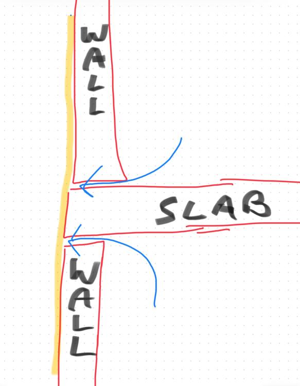
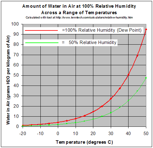
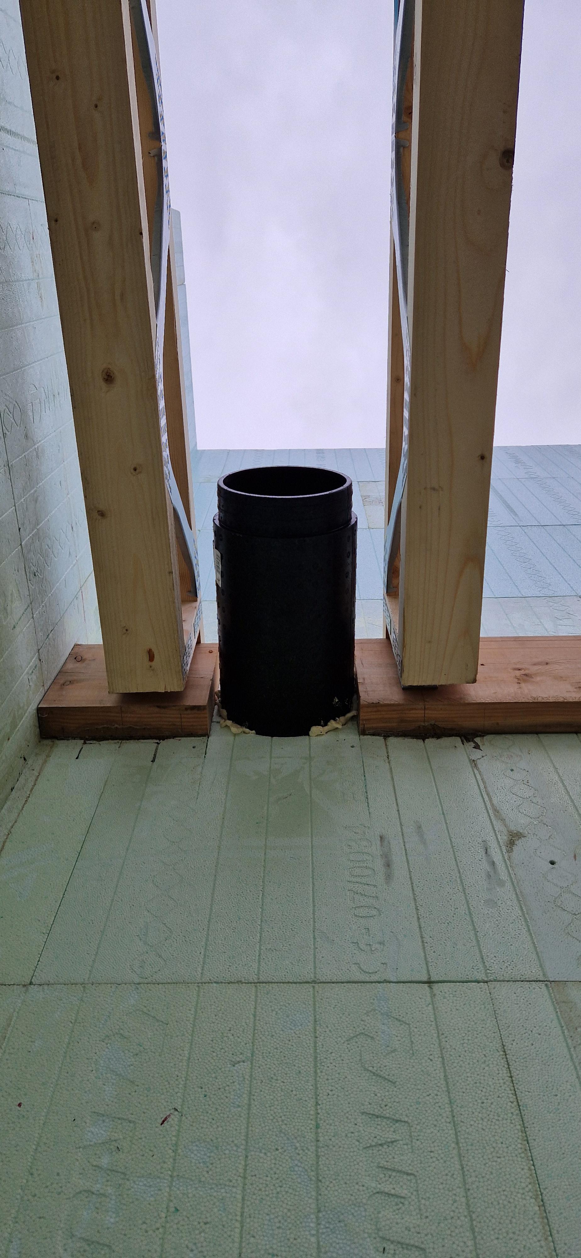
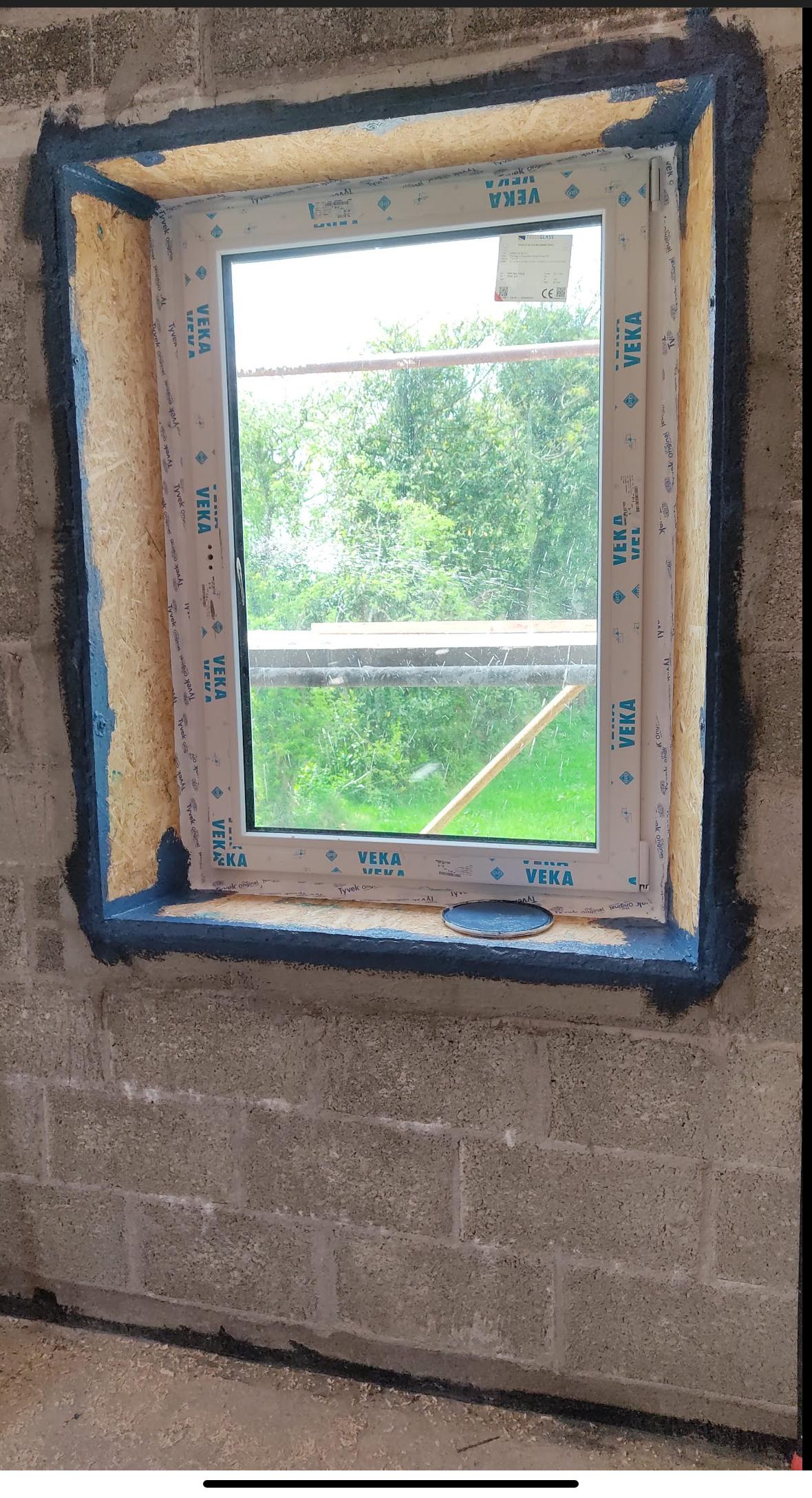
Sure. Vapour needs a surface to condense onto, like a bathroom mirror. If there was an unbroken airpath under and over the slab then it could have moved un hindered until it met the cold back side of the render. Normally done to join two parts of a house together to prevent air leaks at the interface. It's best done with some permanently elastic material like airtightness tape or paint to accommodate any movement. Walls to floors. walls to ceilings, walls to windows etc. the idea is to create a completely airtight seal. Here is how I did our windows and floor. I filled all large gaps with sand and cement mortar and then painted on blue airtightness paint which dried to black. Tape was used to seal the OSB window boxes to the window frame. (For anyone who's interested we used a parge coat first near the floor and around the window to save using up too much expensive airtightness paint). Have you any actual measurements of the bedroom relative humidity? Air tends to equalise pretty well in a house with open doors. You can pick up a cheap hygrometer for less than €10? I'm working on a best guess here. Do you have internal photos too? Was it ok before the Evertex? Has the wall been mechanically stressed regularly , for instance by a football? Over a 1m distance with 50° of temperature difference they will differentially expand by less than 0.3 mm. Assuming the interior of the house is at a relatively stable temperature then maybe the outer 50-100mm might be subject these variations over a year. In any case the differential movement would be 0.01-0.03mm. About the width of a hair, hardly significant. The air leakage is the vapour heavy air from inside making its way to the outside via air paths. Its the absolute humidity you need to think about although its hard to measure so the relative humidity is often used. Relative humidity is temperature dependant though so external air at 100%RH and say 10° actually has less moisture than internal air at 20° and 50%RH. Do you have a mechanical ventilation system? Pictures please. in good light, close and wide shots. Theres no point in finding any products until you really nail what caused the issue initially in my view. Yes if it is stripped back to the bare surface first. However you would still have moisture trapped behind it. I would hold fire on any purchases for now. The moisture that caused the issue originated (i think) from inside. However when this damaged the render then the rain was able to damage it further. I think Ireland is just too wet to consider materials like lime render unless you are prepared to constantly maintain it. Thats why almost all houses here have sand and cement over a block rain screen. It's just so massively moisture tolerant. Its no different from a ventilated metal rainscreen, or timber or fiber cement. Although in a cavity wall it does contribute to the structure it's primary function is to keep the rain off the inner wall.
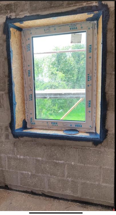
 1 point
 -
Well, @Iceverge , those two last posts of yours are one reason why I keep coming back to BH. Thanks.1 point
-
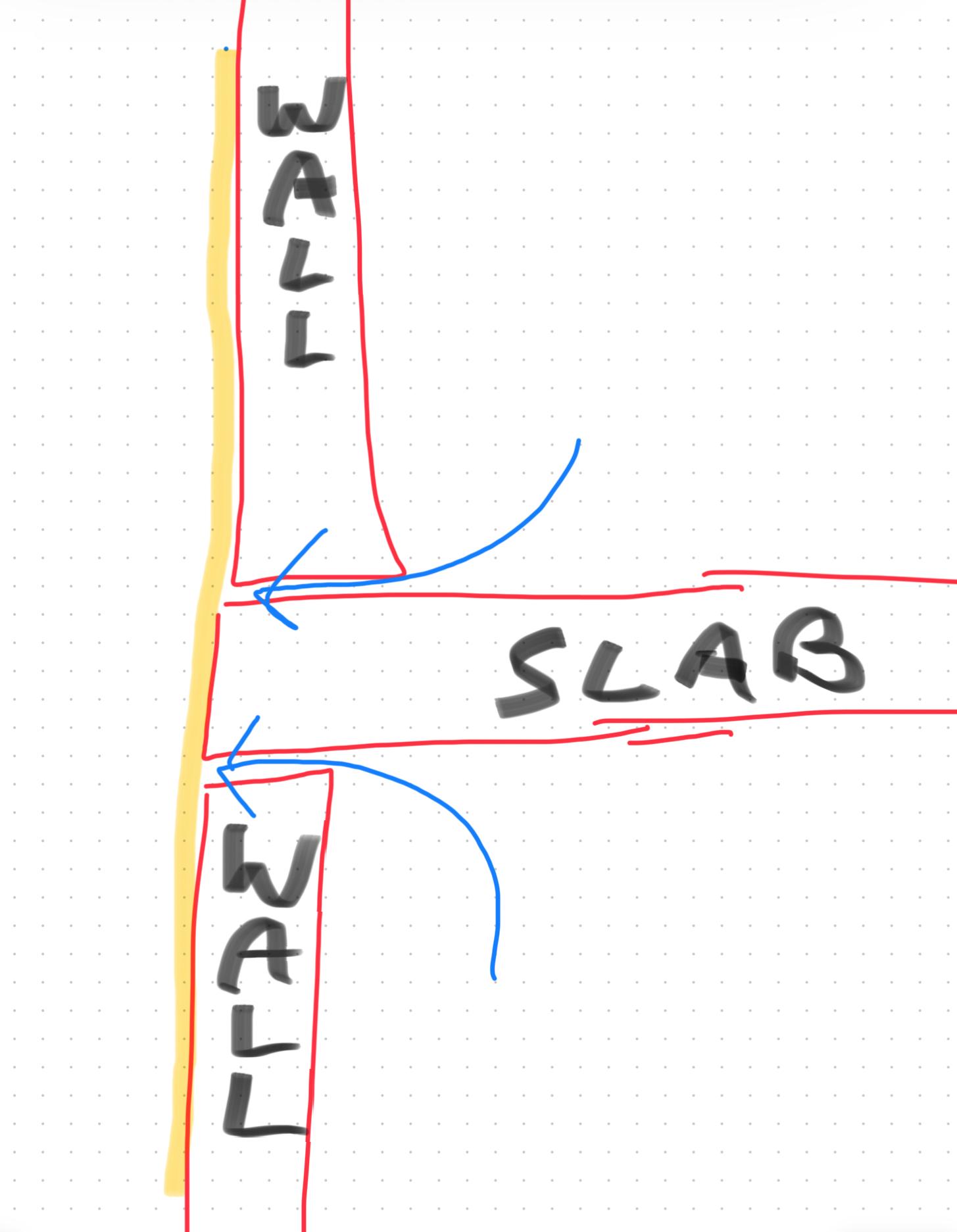
The evertex coating you used has popped up on lots of forums with issues regarding bubbling and peeling etc. They must have had some issues with previous jobs because they closed and reopened under the name https://everflexcoatings.ie As far as I can tell it's a very thick paint, probably of very low permeability. When airborne vapour escaped from the interior of the house via air leaks it got to a point in the wall where the temperature fell below the dew point, the vapour condensed to water and as it couldn't dry out it soaked into the original line render, diluting the adhesives of the lime and it fell off as you can see. My theory is that insufficient air sealing was done below and above the first floor slab. There was an easy path for indoor air of high humidity to pass right through to hit the back of the render. Here it cooled and condensed into water. As the original lime was of high permeability, the condensed water was ultimately able to dry though it to the outside so damage was limited. However when the Evertex was applied the water couldn't go anywhere, it soaked into the lime render and then you had problems, gravity did it's part and the water migrated down the wall destroying the render below the slab area too. The almost perfectly straight fault lines in the render are my evidence of air leaks combined with the impermeable paint being the issue. I would almost certainly rule out differential expansion of the slab and walls as they are similar materials, and the distinct two lines at slab level rather than a complete band point towards air leakage rather than a thermal issue. TLDR: Bad air sealing above and below the slab allowed moist internal air condense behind the impermeable paint dissolving the lime render.1 point
-
NO! Er... we have 970 metres of dual carriageway in Newport! It's just we enjoy the scenery0 points


This leaderboard is set to London/GMT+01:00