Gus Potter
-
Posts
2155 -
Joined
-
Last visited
-
Days Won
26
Everything posted by Gus Potter
-
Have seen an ovalish stone resin bath that we quite like, one of the ones that goes all the way to the floor so no bath panel you can take off to get to the trap or to inspect. The edge will be left clear of the wall. The bathroom is on the ground floor. If the first floor then any leaks would manifest in the ceiling giving you a chance to fix it before you wreck the timber floor etc. Minded to do floor mounted taps.. look like a street stand pipe.. just a tad more expensive. Also may do wall mounted taps. Problem is that the waste pipe needs to run in a 150mm deep solum space so can't get under the floor if it later leaks.. plan for the worst.. hope for the best. Also have under floor heating (wet) and all tiled.. any bath waste leaks are thus not easily found and access is a problem. Was thinking.. can you get a flexible pipe you connect to the bath outlet and run that to the trap. The idea is that you would be able to tip the bath up to have a look underneath where there are no tiles.. don't think the bath will move as it is pretty heavy so won't be tipping it up weekly. Not sure if this is daft or not?
-
Have you timber suspended floors? If so have you popped off any plinths in the utility room and looked behind the appliances. You may find unsealed service penetrations allowing the cold air in from the solum. Utility rooms and kitchens are always tricky on new builds. While the rest or the floor insulation may have had a cursory quality control glance, quite often the plumbers / sparks mess about with the floor insulation when there is a "miss interpretation" of the drawings. It nearly never gets put back properly. I know someone who knows someone who is a site manager for one of the big house builders. They get a heads up from BC on which houses are to be air tested! For all... if you are going to buy a new build ask at the show home loudly if the one you want to buy was air tested.. just for a laugh you understand..
-
Tell us he did coat the underside with patination oil as well as on the top.. pleeeese!
-
flush mounting sinks, hobs - pros cons?
Gus Potter replied to puntloos's topic in Kitchen Units & Worktops
Plus 1! -
flush mounting sinks, hobs - pros cons?
Gus Potter replied to puntloos's topic in Kitchen Units & Worktops
The things we know and the things we don't know we don't know.. or something like that. We have an induction hob in a silstone type worktop, the ones you need to get made. Can't really do it DIY unless you have all the kit. Anyway.. although the hole was cut right in the worktop the hob clips are really tight. I thought.. when the hob breaks down how am going to get it out? With hind sight I would be minded to leave the clips off and just stick it down with a bead of silicon around the edge.. but it was too late by then as we had given it a shove! I sealed it with just the tape that was provided and was thinking about running a bead of silicon round the edge.. Yes on a buy to let I can see how you would like to seal the rim. Not much help but that is where we are at the moment and hoping the hob does not break down. -
Roof Trusses higher on one side by 20mm (not level)
Gus Potter replied to connick159's topic in Roofing, Tiling & Slating
No but you have you have what you have. Do you know why this is the case? Try and figure out just for your own piece of mind if this is an indicator of a bigger problem. Maybe post some more info if you are worried. If you can set you mind at ease then this is a good way to go. Don't forget the noggings / dwangs! On something like this you would be looking at (from memory) a level tolerance of 10mm when it was built . But it depends on age as timber creeps over time so it's not an exact science. -
Very much agree with George's take on this. You could get a beam calc done online for say £150 quid. But the vast majority of the responsibility / liability will fall on you as the home owner to provide all the right information.. and if you are able to do that then you would be able to do the calculations yourself anyway. It's not just the "beam calculation" its how that the beam interacts with the rest of the building and making sure the remaining structure remains stable. This chimney and gallows brackets.. it's not something I would entertain for the following reasons: 1/ Gallows brackets introduce a bending effect into the old walls. Walls in and around chimneys can look ok on the outside but the flue gasses often rot away the inside badly. Thus you have no idea as to how strong the masonry may be near chimneys. Often you can add extra true vertical load down the centre line of the wall to old wall and it is fine but as soon as you add a bending effect it will protest big style. 2/ You don't know what someone will do next door in the future.. they may have already done so and your gallows brackets will over stress the masonry locally as the flues are often offset. 3/ The chimneys act like piers / butresses to stop the party wall from buckling sideways. 4/ In a terrace of houses all these "extra" bits of masonry (chimney breasts, old cupboard walls / coal stores etc) add what we call " robustness" that contribute to stopping the whole terrace from moving sideways. If everyone chips away at this then the stability of the whole terrace can be called into question as this can lead to what we call disproportionate collapse. That is one reason why the councils have clamped down on gallows brackets and types of alteration that compromise the whole row of houses. If it was me then I would first want to be clear what you want to do and then look next door. There are are a couple of possible easy options here using some smallish steels. The steels don't need to be big as they don't carry a large amount of vertical load. But that small amount of "off centre" vertical load is enough to make the party wall very unstable as it introduces a bending force as well as ondinary vertical load. One option is along the lines of this. Run a beam from the front to rear elevation just inboard of the brick flue inside face. Then run a short stub back to the centreline of the party wall. You then build up over the stub and pack to support the bit of the flue above. Here you have the practicable problem of how do we get a long beam into the roof space! You can split it into two or three bits and join it together when you get it into the loft. The other is to run a beam from the party wall back to an load bearing internal wall if you have one. Then you need to work a bit of magic where you know you have spliced beams and that the joints will move when you load up the beam. There are a few easy tricks of the trade you can deploy here at low cost. In summary I would say.. 1/ Avoid gallows brackets. 2/ Talk to an SE. Once you get your head around it you may find that you can do more for no /little extra cost? That could offset the SE fee? 3/ Make sure you get access to next door and take photos in case you get the blame for cracks that are not your fault! 4/ If in England etc read up on the party wall act. 5/ If in Scotland.. talk to an SE.. we don't have the party wall act.. good in some respects.. awful in others. Hope this helps
-
Previous strip foundation needs refilling in prep for a Slab on grade
Gus Potter replied to SHughesNI's topic in Foundations
Yes keep us posted. The frost protection is an interesting one. For all. You'll often see BC / NHBC saying you need 450mm frost cover. But why? From memory if you go back to say 1936 the housing stock was pretty bad so the government set up the NHBC as a gov body. Their remit was to carry out research and develop better housing for us all. Some time later the BRE were formed as an off shoot, much later the NHBC became the insurance comapny that we all love. To deliver better housing we needed some standards that "worked in most cases for mass housing". We know that in a bad winter the frost will get into the ground some 9" -12", in a really bad one maybe a bit deeper, especially if you get a cold east wind blowing at the same time. Here is one theory.. we had concrete founds so we made them 6" thick ( 150mm = two courses of brick) then we wanted say a ventilated solum space and we needed to get some drains round the house but did not want the drains to be below the founds, or at least not below the underside of the founds. Folk also planted things round the outside of the house so they needed some soil depth here. In summary 18" (450mm) to the underside (formation level) of the found seems like a good number. Frost heave happens when the water in the soil forms ice crystals they expand with great force and can lift a found. For significant frost heave to occur you need the following to all happen / soil conditions. 1/ Sustained temperatures below zero deg C so the freezing gets deep enough... that is the obvious one. 2/ A continuous supply of unfrozen water to allow the ice crystals to keep growing... the water table usually. 3/ A medium that has small voids so that when the ice crystals expand they have something to push against to cause heave. One way of explaining this it to look at say a sandy / silty / CLAY. Here the clay is in captial letters indicating that the dominant component is clay. For all.. you'll see this capitalisation cropping up in your ground investigation reports. Excuse the spelling / grammer (I'm left handed) While a true clay is pretty water proof (we build dam cores with it) the above type of soil will probably have sand and silt lenses in it that provides the water path for the ice crystals to grow = frost heave. On the other hand you could have what is called a "well graded" sand or gravel. Well graded means that the soil particles are more single size.. open textured... like a French drain aggregate. If the water table is well below (say 800- 900mm) the underside of the founds then the water can't get anywhere near the underside of the founds to freeze. If so then no frost heave other than a tiny bit where the surface water on the soil particles freezes.. and that is not a lot. You'll get much more movement than this between the house heating and cooling between winter and summer. A big fall of snow ion the roof and so on. You could also technically have a house on large sized stones with big voids, if the water table is down a bit then any ice crystals will just grow into the voids and not cause significant heave.. point 3 in some ways. You could also have a found on fractured weathered rock. Here if the water table is say 600mm below the ground level all tends to be fine as the rock would normally have been there since the last ice age.. your house is just a "moment" in geological time so it ain't going to heave.. unless you are doing some big rescaping of the land and you have really soft rock.. chalks require some careful thought. Yes you might get the " rock flower on the very top" swelling a bit but just scape that off. I mention clay soils in terms of frost heave. Technically you could have say a really good pure clay.. say a cracking London Clay that can be used for dam cores. While it would swell a bit on freezing it would then stop as it is so waterproof that no new water can get in to make big ice crystals. Now that all sound great in terms of frost heave.. but it also shrinks like a "..." in the summer when it dries out and when there are trees and so on.. which is why we don't waste too much time on the technical argument about frost heave in most clay soils. However when it comes to other types of soil, insulated rafts , ICF it is worth having a look at all the design parameters. If you find that the frost cover is driving the design then you need to look at why and the above is a starting point on where to look. The last step is to gather enough site investigation info to make your case to BC and others. -
Previous strip foundation needs refilling in prep for a Slab on grade
Gus Potter replied to SHughesNI's topic in Foundations
Not at all. I like your approach and attitude to life. I did something similar a "while ago".. bought a field, build the garage and fitted a shower and second hand kitchen in it, bought a 14"caravan that we slept in so the planners could not kick us out. Then worked away building the house. Hope this helps. My thoughts from an SE point of view and looking at your photo are: Winter is coming so leave the soil dumplings between the strip founds where they are until you are ready. What we are trying to do here is not to let the frost into the ground and soften it. Let it flood as the water acts as an insulator. If a really hard winter is predicted (-18 C for two or more days) then chuck some stuff back over the strip founds say 200 -250 mm of soil.. this will give you a cover depth to the underside of the strip founds of about 450mm.. which is what BC recommend. Design wise I would say.. what is the finished floor level of the house to be then work down from there and see what solutions are viable. Ground bearing slabs are not that hard to design.. if you know what to look for and most folk don't so that is where the SE comes in. Why would they.. most folk have plenty other / better things to do. From an SE point of view most low rise (domestic structures) slabs (could be ICF) are designed on the basis that we have a number of elastic layers; the concrete slab, the insulation say and the ground below. Think of this as layers of a cake. Each layer working progressivly deeper has different properties. Now we also know that the ground is not uniform horizontally. In your case we have some strip founds (hard spots) intersperced with softer areas.. the dumplings. So now we have a 3D model! One design approach in your case is to ask.. what do we have under the strip found .. is there a uniform layer of say clay 3 -4 m down or do we have a number of different layers. We then look at for example how "elastic" and thick these layers under the founds you have are and how much they are likely to settle when we put a building on top. Next we look at what you are putting on top of the soil. Say some compacted hard core, then say EPS and a concrete slab. We then look at the most elastic layer.. which usually is the EPS and design for that. On a large project we may develop a more comprehensive model.. but that cost thousands as you need to use expensive software, have folk that know how to use it properly and a good comprehensive compatibale ground investigation that also cost a lot.. no point in trying to race an F1 car if the fuel is made by me in my garden shed. But we also look at the number of the soil layers and recognise that horizontally they will not be uniform so depending on the soil and number of layers we also design for the fact that there may be some soft spots under the EPS and we reinforce the concrete slab to span over these soft spots. That's a bit of one design approach. Your best bet here may to try and get your hands on some recycled aggregate.. some 6F2 lay that and roll it in with a 8 tonne roller. What you are looking to do here is pinch stuff from road design. Before you do that try and find a local SE that will come by the site and expand on what I have written. I'll not go into any great depth here but you can use a loaded concrete lorry to do a rolling proof test! Yes it's old school stuff but it works! Leave the strip found where they are as although they are a potential "hard spot" the EPS ect will easily mitigate. I would love to work with you but you need someone local who will be on tap you all the way through your journey. Hope this helps. Keep us posted as interested in your project. All the best. -
Yes, a road kill rabbit apparently does the trick. Has loads of good bacterial in the gut.
-
Raising the roof, scissor or raised tie truss...
Gus Potter replied to bobbert's topic in Lofts, Dormers & Loft Conversions
Yes a well designed dormer can really compliment a roof.- 10 replies
-
- 1
-

-
- scissor truss
- raised tie truss
- (and 2 more)
-
Strip footings or insulated raft?
Gus Potter replied to Selfbuildnewbie's topic in Insulated Concrete Formwork (ICF)
Hiya. I'm assuming they are saying an "allowable bearing pressure" if so, that is a good value to have. 100 kN/m2 is usually used for initial design in say boulder clays. Often rafts are used where say the soil is not so good.. say 30 - 50 kN/m2 It boils down to cost. Strip founds tend to be cheepest, assuming you don't have a basement. SE's say always start with looking at strip founds, then if that does not work you progessivly work your way up through the increasingly expensive alternatives. If you have good ground then I would explore all the other options available before going for ICF even if just to rule them out for you. -
Raising the roof, scissor or raised tie truss...
Gus Potter replied to bobbert's topic in Lofts, Dormers & Loft Conversions
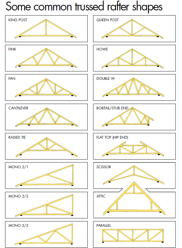
That's a cracking looking project you have there. 1/ Remove the roof.. Yes probably the most practical. Keep that timber! 2/ Option 1. - raise front and back and reduce the roof angle. I would think carefully before you change the roof pitch drastically, you could easily change the character, apprearance.. planning issue? As a guess that looks like about 40 deg.. makes for an attractive, watertight roof.. easy on the eye (well mine anyway). Also in terms of structural design it's a nice and angle as it reduces the bending effects in the rafters as more is converted into an axial load. Option 2 - raise all walls and chimney and keep current roof angle. Now that is an option especially if you have enough matching stone to allow you to hide the fact that you have added say 300 to 450mm to the external wall height. Remember though that you just need the outside to match, you can use a cheeper material where hidden. I would try and keep the something akin to the current roof angle. 3 Install three dormer windows at the front and three skylights at the back (north facing) If you raise the walls then you may not need all three dormers. Remember they are a lot of work = cost. Can you get away with two and say put a feature window in the gable end? 4 New trusses either scissors or raised tie across 5m span of the house. On paper your approach is good.. but this is an old building and they don't take kindly to the horizontal forces that raised tie and scissor trusses can generate at the wall head. Yes you can get special slip shoes to mitigate.. but... then you don't get the wall head tying effect.. see later. Have you put a string line / plumb bob over the existing walls yet? You may find they have been enjoying life and are far from straight and plumb. Nothing wrong with that but it can be a challenge to marry up a modern manufactured truss with an old structure like that. I would have a look at traditional cut rafter roof but with say a steel, timber flitch beam or glulam a ridge beam with simple rafters down onto the wall head. The first floor can then be independant and all that leaves you with a big space and a vaulted roof to really play about with. The main thing here is that with a bit of care you can adjust the rafter lengths and so on to follow the shape of the old building to some extent. At the end of the day it depends on what floats your boat. For me.. if it was mine, (can you feel the jealousy creeping in?) I would want it not to look like I had put a modern square box roof on an old building.. I would want to keep the gutter detail looking "original" and so on... and a good joiner (chippy) can work wonders here. For all: I have copied a bit from and old Wolf Systems design guide which lets you see the typical types of prefabricated roof trusses. The raised tie and scissor trusses can add an outwards thrust onto the old wall heads. They are old walls so SE's are cautious and that can lead to an overly conservative design... underpinning, knocking down bits you don't really need to, replacing perfectly good old oak beams and so on. These "conservative SE add ons" can by far outweigh any savings you may make using prefabricated roof trusses. Over the years I have found on these conversions that the walls tend to lean out at the head. It's rare to find them leaning in. That said though, I did look at one that did but the Farmer had excavated out the inside to make a slatted slurry pit for his cattle. Somebody did buy it and turned it into a house! I suspect the pit was filled in before it went on the market. Let's assume you have some walls leaning out. You are adding a first habitable floor so you put some of the floor load onto the inside of the external walls. This tends to tilt them back the right way. At the same time by using a ridgebeam you take some of the rafter roof load and shed it to the inside walls.. this is load reduction on the external walls which is helpful. You also tie the cut rafter to the wall head.. so that if the wall wants to move further outwards the rafter holds it still as it's connected to the ridge beam.. the rafter acts like a tie. The load is tranferred back up into the ridge beam and taken out away from the external wall or in a place you know is good to go. At the end of the day you play about with the structural design so that you try not to add any more significant weight to the old foundations and that lets you say.. hey the old founds maybe good to go without any major interferance = cost. To make all this work and make the real savings at the end of the day I would always say.. let's look at what we have, how does it behave / work and let's design around that. Every old building is different and that is part of the fun / challenge.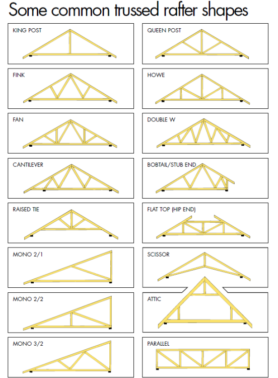
- 10 replies
-
- 1
-
-
- scissor truss
- raised tie truss
- (and 2 more)
-
That's great news. Life begins at 40!
-
From what you say I don't think you are being unreasonable. The following is based on the premis that you have contracted with the Architect to provide a design that meets your requirements and a design information package that is sufficient to enable BC to confirm that, after making reasonable enquiry, your proposals meet with the requirements of the building regulations. I agree. You could end up having to submit endless revisions.. who pays for that and who pays the Builder for the changes? Now that is a good idea. Find a friendly SE and they will easily be worth their fee. Remember that SE's also often know a lot about the Architectural side and so on. The professions cross fertilize. That I find odd as the Architect should at least be providing some guidance here. How on earth are all these different interfaces to be coodinated? What about condensation at the interfaces. Do you have a solum space that you need to infill to install the slab for the UFH? There are lots of things that fall into the Architectural remit. From what you say it raises an eyebrow. To get the best out of BH maybe post your design package after removing identifying info, you'll get plenty info here, as you know, which will put you in a better position to take an informed view. Just check.. the Architect may have copywrited it all so let common sense prevail.
-
Insulating suspended floor from below - VCL?
Gus Potter replied to andyscotland's topic in Heat Insulation
I too have a 1960's house, want to insulate the living room floor. Good news for me is that it's not a kitchen or bathroom so moisture levels will be not too severe. Problem I have is that the joists are built into the inner leaf of masonry on a timber wall plate. Yes.. the inner skin is carrying all the roof load plus two stories of masonry above! I'm still trying to get my head around the best way of doing this. Big worry is that if I cause damp / condensation in the wall plate the whole house will drop! Will keep mulling it over. There must be a way! That is as far as I have got to date, like you that list is a journey.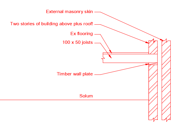
-
Yes Nick good point. Below is a screenshot from a typical truss manufacture. The loadings they use have been in common use for a long time so you can take these as a guide to an old cut timber roof. For ease of reading 100 N (Newtons) = ~ 10 kg so 250N = ~ 25 kg. The load we are looking at here is in the second column in the ceiling tie loads.. called imposed load (loft storage) .. that also includes anything you put on top of the original timbers @Ferdinand.. any legs, secondary flooring and so on. Confusion often arises as there is a difference between long, medium and short term loads in timber design. A bit of wood will carry quite a bit more weight if it is just subject to a load (short term) like a person of "large stature" walking about in the loft checking the plumbing.. but like glass it is less able to carry long term loading such as storage and the bits and bobs ( eg, extra flooring and insulation) folk put up there long term. Loft storage is considered a long term load for design purposes. But if you put a 50 kg tent and can be sure that after you have put in a "secondary floor" that spreads the load about and it will not overload the roof structure then you are good to go. Roughly you often find that if you put in an extra layer of flooring you can add another 10kg per sq m of say xmas decorations. Now to be on the safe side you need a lot of secondary unloaded floor! What folk often do is to say, can I put the tent over a load bearing wall below? Now you need to use common sense and make sure that the wall is truly load bearing all the way down the building. If so then the tent will have little impact compared to the weight of say a load bearing masonry wall.

-
If you want post your plans. It may be that there is scope to have a look at some value engineering SE wise. It may be that SE wise you can't make savings but at least you'll know you have looked at it and have peace of mind that you have looked at every possibility, important before you start to compromise on the things you want.
-
Prices of building materials moving forwards
Gus Potter replied to James Frome's topic in Costing & Estimating
Very hard to predict at the moment, I've heard Network Rail are trying to lock in prices on some of the more specialist work by not going to competetive tender, on the other hand on the domestic side I'm inclined to think things might cool off significantly. In any event having been in the construction industry for nearly forty years, about half that time being a contractor it seems that every seven years or so we get a big down turn.. you set yourself up, maybe buy some plant, even a bigger yard!.. employ more folk and just as it seems you have cracked it and made a little money it all goes downhill fast! That is me using the seaweed test, and if you believe in that we are due for a downturn anyway. Good news ahead for the self builder.. but problem is you can't rely on the plot / house value increasing to make the finances look good. If you do it right though and spend the time on good design and cost control you should still weather most storms. -
Do foundations look right on house purchase?
Gus Potter replied to HazG's topic in House Extensions & Conservatories
Hello HazG Fantastic, still remember when I bought my first house, was a flat but great feeling. You are a step ahead already! Yes, the general concept (particularly in Scotland) is that once you get the thing poking out the ground you have satisfied all the planning condition in terms of a "start" Check the planning portal to make sure they notified planning that they have started work. Before you think about the founds and the floor slab can you tell us why the seller did not complete the build. You'll get loads of help here on BH but to get the best out of it then you need to start at the very beginning.. and work up from there. -
Thank you for your kind words, much appreciated. It took me a bit of time to craft that. It's not perfect but BH is great and nobody jumps down your throat for a typo etc. That said I learn loads here from other folk so for me it's a two way street. You give what you can and your efforts are returned in kind. Hope tomorrow is better.
-
Hi Kelvin. Yes it looks like a Larsen type but what your drawing shows is the outer stud resting on the underbuilding. Could be a quasi Larsen? great proven concept. the Larsen truss. The true Larsen truss allows you to put the load down the inner studs only and this lets you develop a great weather proof detail at the bottom. If you are going for underfloor heating in particular I would go back to basics. Thicken the perimeter insulation up to 100mm PIR and take it down to the top of the founds. This way you actually insulate the dumpling of soil inside the building. Your designers will turn various shades as it will likely be outwith their scope of experience.. but that is what we do in industrial design from time to time. If you keep the floor screed slab back a bit you can carry the perimeter insulation up to the underside of the insulated plasterboard and now you have minimal thermal bridges. Yes in the round use thermalite for the underbuilding.. but check with the SE as you need to be able to prevent building uplift and sideways sliding of the house and that is hard to make work in thermalite. Often we will have holding down straps and fixings between the inner bottom rail and the underbuildings. Let us know how you get on at your design meeting.
-
Welcome from me also. Gus
-
Hopefully this helps BH folk get a further insight into the ins and outs. Here a few extra of my own thoughts. Take two cases. Case 1.. a simple ground beam spanning over a drain resting on a couple of pads at each end. Case 2.. say an ICF basement, raft slab with a waterproofing system. In both cases SE say works out the loads and designs the concrete and sizes the rebar. Then often produces a basic reinforcement layout drawing showing bar sizes, concrete cover, durability etc and a few important details; say the lap length, key corners and so on. The SE will usually carry out a review to make sure that what they have designed can be built "somehow?? " (I hear some of you laughing) and markup up the drawings with some CDM notes and so on. This is then passed to the "lucky" Contractor who has to get on with it. The temporary works are delegated to the Contractor as are all the other problems that go with this type of work. The SE may then be engaged to come to site to check the rebar sizes, spacing and so on just before it is all ready to pour. Now that can work ok on large projects where the Contractor maybe has their own in house Engineers who can do all the temporary works design, carefully check the rebar type, spacing, that the bars are all in the right place and has lots of experience. On small domestic projects this often causes problems as smaller contractors / general domestic builders just don't have the breadth and depth of experience or maybe the resources in house. They often need to get someone else in to do the rebar schedule / provide a price so they can tender properly and so on and this comes at a hidden cost, then the need to install all the bars and shuttering and hope for the best. In summary when things don't fit up on site and the concrete is ordered a lot of money can be lost (tempers fray..) usually by the self builder / domestic client. Designing rebar so it fits and the schedule. Once you have done your "SE" bit the next step is look at the bars in detail and start by thinking "what can go wrong here". Extra long bars or bars that are not basically off the shelf at local stockists could come distorted due to bad handling or may be on a longer lead time.. important later if one or two get damaged on site. Cutting and bending rebar is not an exact science, even with modern machinery. All bars have a length cutting tolerance and when you are setting up the bender the first bar may not be quite right, but still in code tolerance. The ones made on a Friday afternoon may not be quite the same as the ones made on a Wednesday at 10.00am. Some can be over bent, some underbent. Also you get what is called spring back, steel is springy so when you put a bend on a bar all bends won't be the same and this can result in quite a difference and this causes problems at corners as for example. You can reduce the concrete cover to the bars. Remember that the bars when they go into the bender may not be perfectly straight to begin with. If that is not bad enough you have to allow for a tolerance on the shuttering. A shutter that is leaning in coupled with a sprung out bar can leave the bar with little of no concrete cover, and as @saveasteading says in cases they just won't fit at all. Bars that lean in can cause bar conjestion and that means that you can have zones where the concrete is not able to be properly compacted.. to be avoided. Often you say to yourself. Hey if I put laps here I can avoid problems with bars fitting over a wide length between two shutter faces. If I'm using cranked bars in say a basement slab with top and bottom bars can I allow the contractor to move the bars a little in case the cranked bars are a little off. If so, how do I convey this "get out of jail free card" to the contractor. Once you have figured this out you go back and check that the SE design has not been compromised. The bar bending schedule is then relatively easy to produce as you have done all the hard work. Then you check it all again! It's not just burning it's white hot! Take case 1. A simple beam. I'll do the schedule just working off my 2D cad drawing. Often I'll do this for a nominal sum (fee) especially if it's for a contractor I work with regularly or just "good" for the job. If I make a pigs ear of it then I would expect to foot the bill, but that is a commercial risk I take and is lumped in with the rest of the SE design. Case 2. Ah! Quite happy to do the schedule.. here I say to myself.. 2D is not enough, the risk is greater. What I do is to use say Tekla detailing and model the rebar in 3D and put in the shuttering lines. Now I can really visualise where the problems lie and work your way round the model fixing problems, thinking about buildability, pour sequence and size, the weather / time of year etc.. while all the time asking.. have I compromised the SE design. Another aspect here is to make sure you have all the other information you need to coodinate any service penetrations, water bar details etc. Once all that is done then the schedule is the easy bit especially as the software does a lot of the hard work. But again once you have the output from the software I would spend at least a day checking it, just counting bars and so on and a few other things. Lastly you need to check you rebar spec and so on. Quite happy to do this, put my head above the parapet.. someone has to so why not me? If I get it wrong the bill will land on my door step. However I charge accordingly to carry this risk and am careful about the contract terms. Am I just liable for the bars that don't fit or am I liable for any project delay for example. One claim could be a few hundred, the other many tens of thousands. That is something I discuss with the client about what level of risk they want to take on and how much I will charge for the various risk levels. Usually a sensible agreement can be reached where the risk is shared in an equitable way. The main thing is to have the discussion: Is my fee going to result in an overall saving to the client and deliver what they think they are paying the contractor for in terms of build quality and so on. If yes.. then cart on. Another option is where the Client novates you to the Contractor to do this. Basically the Contractor employs the SE directly and carries the risk. But on self build this is complex contractually especially when you are trying to nail down prices to get say funding for the build. In summary. If you are self building then the above is worth a look at as an approach. It's a balance. The more you spend on the design information the easier (we hope) it is for builders to deliver. Also less risk at tender stage as contractors if they are unsure at tender stage about something will just add on a big number and think to themselves.. if I get the job I can afford to worry later about how I'm going to do it as I have a big profitable lump sum built into my figures.
-
Have a look at this guide to good lead work. Easy reading and should help you out. Tells you all about max lengths of lead and the code (thickness) of lead to use and where etc. It' one of my go to guides. https://www.google.com/url?sa=i&rct=j&q=&esrc=s&source=web&cd=&ved=0CAMQw7AJahcKEwjA-KCI3NH6AhUAAAAAHQAAAAAQAg&url=https%3A%2F%2Fwww.calderlead.co.uk%2Fuploads%2Fdocumentsearch%2Fid4%2FCalder-GTGLW-210213.pdf&psig=AOvVaw07OgmkkR7N57A4sfbm148e&ust=1665355815925499