Gus Potter
-
Posts
2342 -
Joined
-
Last visited
-
Days Won
29
Everything posted by Gus Potter
-
Yes sometimes it can be that simple.. no need to panic... easily fixed.
-
Yes once you can put your finger in it.. it is a structural crack! One thing that I have in mind is that the side walls of the extension are resting on the ledge (scarecement ) of the original house founds and the front of the extension has settled... hence the widening gap as you go up. But it may not be that obvious so I need to rule out all other reasonable causes as best I can. There are some trees lurcking about, different ages and varying depths of founds, leaking drains and Network Rail have been messing (piling for electrification) about near the site apparently.. will investigate next week but will put on a shirt etc and some head gear on so I "look official" before I go for a wonder around the public part of Network Rail property. I will go look at as many possibilties I can think of but want to check that they have been doing next door... very important. I'll keep posting when I can so folk can follow the process and how I reach a reasoned and evidence based conclusion.
-
Yes do that. Let the misting suppliers do the leg work for you and explain how their system is compliant or not with you requirements. Remember that it is in their interests to sell you their system. Send them the drawings and give them as much info as you can.
-
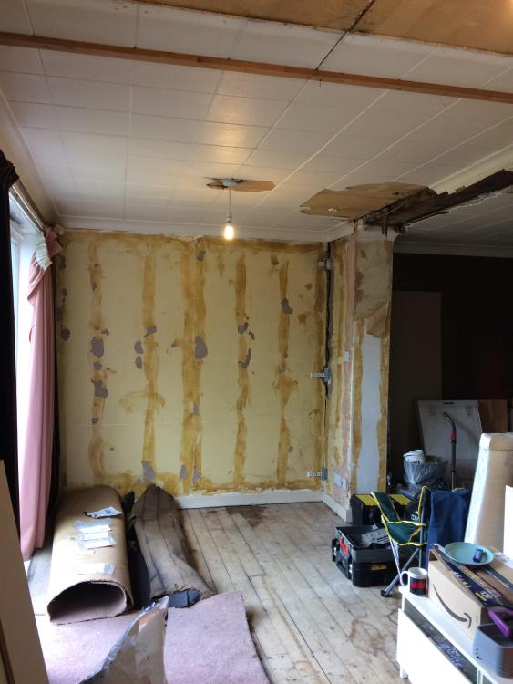
For BH folk that have "movement" Today I was installing tell tales to monitor movement or not. Have a Client that wants to refurbish and expand an existing rear extension. But the existing extension we want to upgrade has parted company with the existing house. You can see the "partin some 1.0 m to the right of the light bulb. I need to know if the movement has stopped or is relatively benign before I go ahead and design the upgrade. The extension is on CLAY soil so expect some seasonal movement. The photo below shows a smallish crack at low level and at the top there is some 14mm of separation. Now the Client wants to install a kitchen along this wall so if I don't get a handle on this then.. well.. trouble ahead! The house is semi detached... the neighbours have just introduced some kind of steel box frame next door as they have knocked out the back of their house.. I think they have added load to the party wall foundation. I want to make sure that my Client is protected as if later if something goes wrong.. my Client will get the blame to start with... best to be prudent as "last man on the job gets the blame" . I'm monitoring partly to see if the folk next door have caused an extra problem. You can get tell tales that do corners but they don't give you much room to get a drill in to fix them. Here I have cut brackets from offcuts of metal framing so have much more room to play with. The whole lot is screwed and fixed with construction adhesive.. so I can be sure the screws don't slip. The tell tales are actually quite fragile so you need to be gentle with them.. again the adhesive cuts you a bit of slack here and allows you to adjust the tell tale alignment. I installed six tell tales and it took me about six hours.. you need to take your time as the surfaces you are fixing to are rough and the tell tales need to align. But there was a bit before today. I spent time looking at the job and identified about six possible causes for the movement, there may be more, I need to sleep on it further. The main thing is to think of everything that could cause movement, be logical, look at probablilty and narrow the field down.. I think there may be more than just one cause here. The nity gritty of the tell tales. They have a cross hair that sits over a paper grid. They come with pins that lock the cross hairs over the zero point of the grid. While you screw them to the wall the screws can't be too tight as they crack the plastic tell tales. It's the adhesive that does the real work holding them in postition. I'll leave them for a couple of days for the adhesive to set and then take out the pins. Hopefully the wall is not moving that much that the pins shear or the tell tales fracture over the next couple of days..! When I take out the pins the cross hairs may shift, hopefully not, then I'll record what happens over the next few months while we get the planning permission in place and detailed drawings / structural calcs for the BC permissions. My gut feeling is that things will pan out ok.. but I need to do some monitoring to mitigate risk and be responsible. In posted this as I hope it helps BH folk see how we go about this and how you could do this for yourself as an excercise. If you go about it the right way, photograph and take records then who can doubt you?
-
Well that is a positive start and there is loads of great info in this thread. This sort of thing can cause concern but if you gather the facts the problem / concern can go away. I'll put my own slant on this so here goes. The legislation in Scotland works on the basis that the polluter pays.. last time I looked the same principles apply in the rest of the UK. Thus it is OK in some cases to have a septic tank..(they are not illegal in Scotland and certainly existing septic tanks in the rest of the UK) a big brick tank or glass fibre type bottle sunk in the ground. In Scotland when we want sell a house we need to register the tank.. it can be any tank.. spetic or a tank that treats the water to some degree often called a package treatment plant. In a septic tank the soil water from the house goes into this and settles out, heavy sediment on the bottom and fats on the top. There is an outlet that is designed to sit below the fat layer and this cleaner water goes into a soak away. Now you can see that the only "treatment" that occurs in a septic tank is a process of separating the fats and heavy material.. there is some Anaerobic digestion that takes place but ignore that for now. A septic tank is designed to make sure the water exiting from it does not block a soakaway, the biological oxygen demand, the ammonia content and potential "pathogen" content is not a consideration as this water soaks away safely into the ground. The main consideration is that the soakaway is far enough away from a water course or potable aquifer so as not to pollute and designed well enough so that the water going into a soakaway does not appear somewhere else.. often occurs if you are on a hill. If was buying a house with a shared septic tank I would concentrate on the practical side then look at the legal: 1/ Where is the tank and what type is it? A septic tank, a packaged treatment plant... there are a few different kinds, the modern ones tend to need less maintenance = cost. Water flows down hill so if the tank is in someone else's garden then they will suffer first! Sounds awfull but if sewage is bubbling up in your garden and the neighbours are not playing ball then you can face an uphill struggle.. causes friction. 2/ Next.. a really important is to know about the soakaway. Where is it and how much space is there round about it. Sometimes you find that the soakaway is not within the curtilage of the dwellings that use it.. say in a farmer's field. Now often there is provision in the deeds that allow you to access the field for maintence of the soak away.. but once they get blocked.. which they do eventually then you often need to shift them a bit as the pores in the soil get filled up.. will the farmer let you do this? If the houses have big gardens and the soakaway is within the cutilage of the dwellings that use it then you have scope to relocate the soakaway to some extent. But again where is the soakaway.. in your garden or elsewhere. Who gets their garden dug up? Now it may be that you don't have a septic tank that discharges to a soakaway, rather you may have a treatment plant that treats the water like the public sewage works and discharges to a water course. This is different but not a problem once you know enough about it. In the round if you love the house then start having a look at the practical side first .. then check the legal stuff.. cheeper to use you own common sense before paying legal fees.
-
Can you bridle around the area like you would do a stairwell, now you don't need to hole the bottom truss chords? Maybe you need to double up the bottom chords or make the trusses if Engineered with a thicker flange or if standard trusses make these out of a thicker (not deeper) timber. That may make the problem go away and give you much more play vertically and horizontally when you actually install the WC.
-
Extracts from BS EN 12056 - 2:2000 For a WC the pipe diameter hinges on the outlet size.. which kind of makes sense..


-
Have you had a look at the cost of the water mist systems? Also they can be much less onerous in terms of water storage capacity and mains flow rate. There are a few companies on the internet that do them and you can send them your drawings to get a no obligation quote and some free technical advice. How many floors do you have? It sounds like you need something along the lines of an grade D system and the number of storeys will dictate whether you need and enhanced grade D or not, assuming a normal domestic dwelling. Main thing it to plan you fire strategy taking into account the early warning (heat and smoke detectors) and the fire suppresion system. This way you build confidence that you have the over all design right at a sensible cost.
-
Also ask about using a cluster of timber studs under the beam end.. much easier to fix timber to timber. Let us know how you get on and what solution you go for at the end of the day.
-
Can you post the drawing again as the notes are hidden a bit odd? Also can you post a ridge detail and what you are doing up there? Do you have dormers? what is happening there at that interface? Are you putting an ensuite in the attic? It does look like you have some kind of hybrid roof, I have nothing against them but you need to understand how the tiles are fixed, vapour control.. what you have posted looks far off what you need to certify the design is ok both in terms of insulation and tile fixing. Oh and lastly has anyone thought how all that is going to work structurally? Can you tell us a bit more about that?
-
Advice Needed - Bonnet Hip Tiles
Gus Potter replied to ProblematicPanda15's topic in Roofing, Tiling & Slating
My backside. A hip should be straight up the line of the apex, even and pleasing to the eye, who told you otherwise? But to make a cogent argument you need to start on the inside of the roof and see how the rafters frame into the hip timber. If the joiner has made a pigs ear of that then the poor roofer is fighting a loosing battle.. in fact the roofer should have told you.. I'll do my best but your timber roof is crap. If you can show that the timber roof is ok then next look at the tile battens and so on.. go through it step by step, if it transpires the roofer has cocked up then fair enough. However that hip is a mess. Try and understand what has gone wrong and then work with all the folk that had a hand in building the roof to make it look a bit better. I think geometrically the problem has started at the eaves as the roofer has not understood how the angles work. It is really hard to get your head round this so mistakes are common. But I think most of the problem lies in just bad workmanship, not using a stringline and not using the correct mortar. -
Ah what's the saying.. You can take the Engineer out of the Contractor .. but once a Contractor you can't take it out the Engineer. I think you just need to live with the fingers and that contracting is in your DNA..
-
Loads of folk have made some good points. Here is a thing. There are two kinds of soil investigation.. a factual one and an interpretive one. The factual one just gives the results of the investigation. I get these and it is then up to me to work out what loads I can put on the ground where. In this case I carry the can if it goes wrong.. obviously I want to avoid things going wrong. The interpretive investigation passes the liability to the Geotechnical / Soil Survey Company. Here I get a report that says things like.. Bearing capacity of the soil is 100 kN/m^2. Plasticity is this / swell shrinkage is this and recommended foundation depth is this... taking into account environmental things like trees ect. Soil is "acidic" in nature thus recommended concrete grade is this. For all.. some soils can be contaminated some acidic and aggresive to concrete so you need to select your concrete grade based on this information. Ground water was found here but could vary by x.. very imprortant as you don't want you raft floating. Now a lot of these companies I deal with are very helpful and give you a heads up if you pay for the more expensive interpretive report. They tell you things over the phone like.. we have worked locally so here is what to also watch out for and here is what you can disregard. But to sumarise. Before I commision a soil investigation I do a desk top study just to get an idea of what kind of founds may work. No point in going for a raft on rock / good chalk. There are load of more efficient ways to skin the cat. Yes basically you are. In terms of working with a remote Engineer. Yes it can be done. I do some jobs this way where I never go to site. BUT.. this only works if the Client fully engages and spends time learning about their site, the ground and how their self build / extension is going to work. In other words the Client puts in a good effort and becomes a fully invested part of the nitty gritty design team.. imagine yourself as a young graduate .. you are not daft but you don't know very much but are happy to learn.. and once you have learnt you get to make the important design decisions in terms of say structure .. how the drains work and so on. This will take time but if you adopt this approach you will gain a huge amount of confidence. You'll also know that later in the project.. say if you go on more on your own then you can always call up the professionals that helped you at the start if you get stuck. They say that site investigation should take up about 3 -5% of the budget by the way. A lot of professionals have a wide range of knowledge. Architect's know about structures, SE's and Qs's about design.. some good builders fall into the same category. In the round though if you spend the time to learn it can take you away from the day job that often pays the bills. The upside is that you reduce your risk and the process can be very rewarding personally... and that is hard to put a value on. @Barny Keep us posted.
-
Have you had a look at the extra load potentially that you are adding to the roof structural timbers. That may cause a problem if you come to sell. I am starting to see a bit of uptake in folk wanting a report and structural calcs for fitting PV on existing roofs. Assessing old roofs is challenging.. but a lot of fun as you get to delve into the history of the structure. You may think.. big old timbers, I think yes fair enough but the nails holding it together are rusty! for example. Also a lot of these old timbers were are working on the edge.. they look big but tend to be on their span maximum. Over time some of the bracing may have been taken out, the batten fixings are nail sick, loss of stiffness in the roof etc. Next.. you are putting on PV panels.. surely the roof under should last as long as the panels as they are a big investment.
-
An introduction... Renovation + 1950s + subsidence = a challenge!
Gus Potter replied to alfaTom's topic in Introduce Yourself
Double post here alfaTom... as I'm on a roll. Last post was about the ground but once you know how you building works what next.. how do you design to take account of the movement? To start.. what do you want to do internally. First I look at where the movement takes place. If we wanted to change some non load bearing walls inside then look at doing them in light weight frames, could be timber or metal stud for example. But these panels are quite stiff, but not heavy. You have a square and stiff panel attached to an old building that is moving up and down, probably differently at the edges of the panel. An easy way of dealing with this is to introduce shaddow gaps around the edges of the stiff panels so the movement cracks are hidden. The beauty of this is that it allows a huge amount of flexibility in the interior design.. and future proofing. You can change each panel without having to redecorate the whole room. Floor coverings.. well go for flexible floors that can take a bit of distortion.. say 25mm! That leads you down the timber / carpet /Lino tile type route. You could have small areas of ceramic tiling.. but that will come at a cost. Externally you can use drain pipes to hide joints, sometimes plants.. a treliss.. If you want to make structural alterations inside, say knocking a hole in a wall then you end up with point loads on the founds / underbuilding. To get around this you can use a box frame that "tricks" the found into thinking that nothing has changed above. Going back to you original post I would explore every avenue before commiting to underpinning. -
An introduction... Renovation + 1950s + subsidence = a challenge!
Gus Potter replied to alfaTom's topic in Introduce Yourself
Yes do that before you embark / commit to anything. You could potentially save thousands here.. pick the wrong solution and you could lose thousands more! My immediate thought is this.. well I'll start with a bit of background info to explain... and Linconshire is a great example. For all. Often you may think that deeper founds = more soil bearing capacity = more load you can put onto the ground. But in parts of the UK we have "upside down ground" yes deep down there is rock / good sand / gravel etc but this can be far down.. Here the ground nearer the surface has a stiffer crust and below there is softer material that doesn't behave well. In other words digging deeper causes more problems than it solves. A lot of houses in Linconshire / small industrial buildings too have deliberately shallow foundations that sit in the stiff crust near the surface. The load is then spread out so by the time it reaches the softer layers the stresses are reduced on the weaker layers. The reduced stress causes the lower layers (weaker soil) to compress less and this reduces the settlement. @alfaTom If you look at your results you can see that the shear vane value reduces a huge amount with depth. We use the shear vane value as part of the calcultation to determine the bearing capacity of the soil. Also you can see that the soil classification changes with depth. At all levels you have what is called a plastic soil.. more prone to settlement. But the deeper you go the more plastic the soil becomes.. in other words worse. The trial pit result shows that the soil changes to something possibly more favourable at 3.4m depth as it is starting to transition to a sandy layer which is more ameniable.. but you may need to go a good bit deeper to get to something sound. There are loads of houses in Linconshire and elsewhere that are built on the stiff crust. The house does go up and down a bit but the secret is that it all moves up and down at the same rate and that is why many of the houses have not fallen apart. You have two different types of loading on the soil.. from the single story part and a two story part. Both load the soil differently so will move by different amounts, hence the cracks you see. Do you know what came first? This underpinning stuff.. what are the companies proposing? and how much? I think more time needs to be spent understanding how this old building works and the ground under. Then you design for the movement when you want to make changes, save a load of cash. You SE has said that the cracks are not a big problem so the building as it stands is not structurally unsafe. If it was my house I would be asking the underpinning folk.. are you sure that you are not going to make things worse and can you prove it! Looking ahead you may want to extend and go for high insulation and energy efficiency.. say Passive design concept. Here what we do is excavate out the soil, stick in loads of EPS and deduct the difference in soil mass. we play about with and take advantage of the light insulation and balance that with the loads the old house is putting on the ground so we can make a good attempt at making the old bit and new bit move up and down in the same way and that reduces differential settlement. Just if we do this we need to make sure the new bit does not float as EPS is lighter than water.. we need to look at water table and flood risk. Once you get your head round the fact that your building moves up and down you then design your investigation strategy around this. You gather the facts and prove it SE wise.. they did it for the Pizza tower.. we can do the same in Linconshire. for less cost! Crack stitching in this case on this type of soil often just results in moving the problem somewhere else. Often we want the building to be flexible.. like using lime mortar.. so we get lots of little cracks rather than a few big ones. Keep us posted. -
New extension cracking - advice please
Gus Potter replied to John543219's topic in Introduce Yourself
What is on the inside? another masonry leaf? If so does the crack appear on the inside. If so you may have a problem on your hands as the tying together of the building needs to be checked. How long is the wall? On the other hand it could just be the blocks shrinking and the crack manifests at the weak spot. -
Yes I think they do but from that value you need to take of the cost of an SE assement. I have surveyed some steel portals.. with a view to extracting extra capacity, say by adding an extension or a mezzanine floor. Have had reasonable results but.. you need to be very careful. You need to get yourself there and examine it in detail. I would be very wary about trying to reuse a concrete frame.. there are not just issues around strength but bar cover. When these things were made there was often no quality assurance.. if you don't know how the thing was cast and how well then how do you justify it will perform? Last man on the job gets the blame! Now if you are an SE make sure you take a micrometer to measure the flange and web thickness as for a while folk were passing off Chinese steel as BS sections. They look the same but the web and flange thickness is thinner and the steel grade who knows? For all.. if you are doing things that require steel box sections for example then there are two fundamental types; hot finished and cold formed. The cold formed tend to be cheaper.. but don't do the job. If you are going to buy something second hand then you need to really do your research.
-
Invaluable knowledge disseminated. Thanks for that.
-
This all sounds very complex.. a few watts here and there? In my bathrooms I have UFH, but going for an electric heated towel rail, say 150 -250 watts so that will be on and off in the summer, UFH off. Enough to make the bathroom feel warmer, actually quite a bit warmer as well insulated. But are you off grid? Look this thing about UFH.. we sit here doing theoretical stuff about weather compensation, floor coverings , all sorts of techy stuff, flow temperatures etc. All of that takes complex controls that break down, valves get sticky after a few years and the folk that supply the say Hive controls keep updating their software. Yes it may look great on paper just now and you may think I'm a philistine. but I was doing this stuff 30 -35 years ago! So I know about the hidden long term costs. Just have a think about how much it is going to cost you to replace the moving parts in five years time say! A twelve way manifold.. the flow control stats! Software updates.. the usual replacement of zone valves.. and if you need to drain down the system.. the inhibitor cost.. it seriously racks up the running cost. But in real life folk try and make do so you end up paying for something technical that works for a bit and then is crap. The intrinsic beauty of UFH is it's simplicity. In my current house I have UFH. The water goes into the manifold at about 30- 40 deg C. The flow through the loops is controlled by some hand turned gate valves. I have a couple of room thermostasts. I have adjusted the flow in the loops maybe twice in the past four years. The maintenance costs are well so far well pretty much none. Yes, on the odd occasion it gets too hot or not hot enough.. but it really is on the odd occasion. When I balance that with the low maintenance / environmental costs I do get the last laugh! What I'm saying is that folk are trying to make UFH into something it is really not suited for.. by introducing all these controls that also need future maintenance. Then folk try and calculate things to some finite degree for flow temperature and zoning.. but they then stick a big sofa over the floor or a rug.. which make all the calcs invalid. If you have a well insulated external envelope then the heat is trapped inside.. you don't lose it.. but you can open some internal doors !
-
Drywall screw length, is 35mm too long?
Gus Potter replied to Thorfun's topic in Plastering & Rendering
Posts overlapped there! -
Drywall screw length, is 35mm too long?
Gus Potter replied to Thorfun's topic in Plastering & Rendering
No 35mm is probably the shortest length for fixing plasterboard if into timber. For plasterboard 9.0mm or 12.5 mm thick I use a min screw length of 38mm. The rule of thumb is that of you are fixing something to timber the embedment length of the screw needs to be 2 x the material thickness you are fixing. Thus a 12.5mm plasterboard needs 3 * 12.5 = 37.5mm. One key thing about fixing plasterboard is you use a bugle head type of screw and screw it in so it lies just under flush of the face of the plasterboard without breaking the paper face. It takes a bit of practice unless you have an auto feed type of screw fixing tool with a depth setting. I would encourage you to do it with an ordinary battery operated screw driver as when you get to corners you may need to use a battery drill anyway. If you go onto the Gyproc website and Utube you can watch videos about how to fix plasterboard correctly. Gyproc tell you how close to the edge of the plasterboard the screws can be and the correct screw spacing for walls and ceilings etc.. There are two edge distances. One is if the paper is left intact at the edge of the board, you get this with tapered edge plaster board, the other when you have cut the plaster board and you have a weak edge, you also get this with square edge plasterboard as the paper does not continue around the edge. Main thing is to read up and then have fun! -
Low Level Brick Spalling / Brickwork Fracture
Gus Potter replied to azureblue's topic in General Structural Issues
Good to help out. Yes looks like some potentially significant movement has taken place. Photos showing the wider context would help a lot. Don't forget to include the roof so folk can get a full picture of how the building may be loading the wall. -
Yes Fourier could be applied but does it work with an infinite depth of material when you are dealing with a soil?
-
Yes it's a bit of a mine field. Starting with the design codes a lot of the ground floor heat loss calculations you get using the online calculators are based on on BS EN ISO 13370 (2017) and BRE 443. I'll leave suspended floors out for now as a different approach but take ground bearing slabs. The following is a rough explanation.. but this is kind of how it works. You have UF in some kind of screed or could be in the structural slab, that sits on insulation. We know the thermal conductivity of the insulation. But to make things efficient we need to look at what is under the insulation and around the edges.. the ground will heat up a bit and once it does where does this heat go? Heat leaks out in two dimensions, down and sideways. Now often the online calculators often attribute a thermal conductivity (the Lambda value based on clay soil) of the ground below of 1.5λ (W/m.K) . Imagine we had a huge warehouse.. that ground has an insulating effect. Now as we don't have a warehouse we modify the calculation for the size of the slab.. and that is where you get the perimeter / area value from as this takes account of the heat that leaks out the sides. A small slab tends to have a P/A closer to one, a large slab say P/A of 0.6... big area vs perimeter. Now when you work out the perimeter area you need to make a judgement on whether is is just the edges of the slab next to the external walls or do you need to include the edges that face into the building.. matter of judgement on how you are detailing it all but you can make savings here if you are struggling. Often if need be you can offset by adding a bit more insulation in the easier parts of the build. Turning to the maths. We start with the thermal conductivity of each material, its thickness .. add up and reciprocate to get the U value. @SteamyTea and @Carrerahill et al. The ground thermal conductivity works I think on the principles of an elastic half space.. an infinite depth, same kind of principle pressure in soil modelling but coupled with flow of electricity through a bus bar. The maths I think are based on the Laplace equations for three dimensional flow... which can be water / electricity or heat. Now @RobTristram if you start to struggle you can put extra insulation down and around the perimeter. Say take 50 -75mm of insulation board down the inside of the underbuilding to the top of the founds. This could get you out a hole and will actually work. @saveasteading knows more about this and the practicalities. For me I would would take the online U value calculators assumption of perimeter thickness of insulation (often 25mm). Then if I at least double the depth and increase the thickness buy 3 times I would have a stab at demonstrating that I can reduce the P/A value by say 25- 33%... not below say 0.6. Now that thickness seems a lot but if doing a TF / maybe dot and dab insulated plasterboard on masonry it can work a dream as it marries up closely with the thickness of insulated plasterboard... you get some continuity of insulation. Life does have a bonus from time to time. Once you have got the thermal conductivity established you can then look at your delta T and play about with that.