Gus Potter
-
Posts
2341 -
Joined
-
Last visited
-
Days Won
29
Everything posted by Gus Potter
-
That is indeed civilised. The main thing is that whether you are an Architect, CE or SE you realise that you carry a lot of responsibility. They all can be a great profession but you can often be held responsible for your actions and that is often not commonly recognised in day to day life. There are other job that pay better with less personal responsibility.. banking for example?
-
Hello @ETC Thanks for the clarification. I suspected I had not got it right. SE's need to keep run off cover also. In an ideal world when you retire from say a practice the younger folk take on the "office" and agree to pay it off in installements while taking on the costs of the run off cover.. call it succession planning. I work with some younger Architects and they have been discussing CPD, I thought (wrongly) that you had to do this now. CPD comes in all forms, some is technical but all construction professionals should have an appreciation of what is going on, not just the construction industry but the world in general as this drives informed decisions. That is what makes a true professional. For our SE stuff CPD can come in many different forms. Believe it or not me posting on BH can be counted as a couple of hours over a year.. we say that is pro bono and justify it by saying.. it's "good for the sole" we may also do some charity work and so on. Thanks again for the info and explanation. Now I know!
-
As the mould / damp bit is at the bottom I would take off the plasterboard on the window ingoe where it is at it's worst. Yes there will be a bit of disruption but it is the best way of getting to the bottom of the problem.. UPvc windows are fine .. it's the fitting of them that 99% of the time causes the problem. Two basic things I would look for and suspect.. 1/ Window fitters are notorious for not closing and installing the cavity closers properly. They will shove something in for good looks but particularly on a retro fit you often have mortar snotters and wall ties in the way. They are pushed for time so often don't care. 2/ You have a cill that should be sealed to the bottom of the window frame so that the water drains out through the front, usually done with a bead of silicon when the cill is fixed to the window before installing. Check to see if there is dampness when you open it up. To make sure get a hose and spray it on the window for 10 -15 minutes and look at the bottom corners.
-
Yes some Architects give up their Archictect's registration... RIAS in Scotland as to maintain your registration you have to do CPD and so on which can be quite onerous. You need to keep paying your professional registration fees. The main thing is that once they give up their registration, "retire" the can't call themsleves a Chartered Architect as it is a protected title, I think they may be able to call themselves Chatered Architect "retired" @ETC do you know? However there is no bar to continue working away and insurers are quite happy to keep writing the PI cover. Why would they not.. someone who has that amount of experience is less likely to get it wrong than someone just starting out? The main thing is; if they finally hang up their boots you make sure they have run off PI cover that usually runs for 5 years or you can say.. We will carry the can after a year, or less and just enjoy working with someone who knows a lot. Now often if say an Architect has been working for a practice they will be over the vat threshold, once they wind downand start working solo their turnover drops below the threshold so great for folk wanting an extension say... not vat on the fees to pay. I would encourage you to look carefully at what is on offer.. you are going to get a wealth of experience, sage advice from someone who has seen and done it all for probably a not bad price?
-
At a quick glance the bit to the side is fairly benign SE wise. But if you extend to the rear then I think you will have building stability issues as others have mentioned. This can often be resolved using a steel box frame.. but it will stick into the room a bit. That sounds bad but often in practice it lets you still have an open plan space that you can separate into different "zones" say dining room, kitchrn and so on.. still feels open plan if you can post more drawings showing the rear elevation. Initial guess would be about 6.0K for a box frame to open it all up.. but we need to see how the roof works first!
-
To add a bit and for clarity. When retaining walls get to a certain height they can become expensive if the ground is not playing the game. An easy way to mitigate this to introduce restraint at the top. For all.. sometimes you can brace the top of the retaining wall off the house.. and that can save thousands!
-
I shall oblige a bit but don't disagree with you .. To touch briefly on the the laws of economics and so on (see for example Ruskin) and the divesion of labour. Over time, the professions and the way we work, the things we are employed to do have become more specialised. Take Structural Engineering.. we have folk that can make highly complex computer models. To give you an example.. at the higher end a good finite element package subsciption will cost you 25k for a year and you only get to run say 5 or 10 full scale models.. that is 2.5 to 5k a pop! Now it takes a long time to learn how to make a model like that and make some sense of the results. You are probably not going to know much about all the other things that need to come together to get something built. Also you need to be able to convince others that your model is roughly approximate to what happens in real life as folks lives are on the line here. But if we are to make progress we can't be stuck in the past. we need these models to deliver efficient design, it's about verification, comparison with other computer models and so on. In summary design is often driven by cost.. to reduce cost we often need to specialise.. make ourselves more efficient but that gives us less time to appreciate and engage in holistic and good design. You can see this on BH all the time..comments like the SE is not responding and so on or the Architect is blanking us. Hopefully the Professional bodies will come to their senses and recognise that while at the moment they think they have invented a new wheel they have actually not. The best Architects, SE's and CE's, Building Surveyors etc have a rounded knowledge and will at some point be schooled again about who pays their wages.. folk on BH for example.. and be taught about the business aspect of being say and Architect and the fact that you ned put put in a bit of elbow greese to make a go of it. Yes to start with but some of us then become Architectural Engineers.. there are some great examples world wide. When I was at Strathclyde Uni they ran a course called Architetural and Structural Engineering which was recocgnised by the Engineering Council. It was a good course for students that wanted a half way house.. I think they all got jobs at the end of the course. Don't think I have obliged you on refection but hey ho.
-
Hiya @PXR5 For me I would have a look at this all over again.. a design review now you have got a bit of a heads up and starting to appreciate the costs / things involved. In terms of appreance I would look at where the sun rises and sets, how you are going to use the space between the wall and the house. Would be helpful to have some more plans and so on.. do you like lots of plants or do you see this as a place for kids to play and a spot for your outside bar/ bbq ? let us know if you can. A bit of thought now can reallty make or break this. May be worth you while posting? The next is in no particular order it's just my thoughts. Here are a few SE / Geotechnical / risk thoughts. To get started on this the last thing you need is for your neighbours to get upset. You don't want to do something that will cause the land to slip so it impacts on their house but in real life their garden may tolerate say some 25mm of movement top end without complaint.. especially if they have grass.at the rear. A 2.4 m retaining wall can be a big ask if you are on a budget. My worry (not least) would be that when your neighbours house was built they maybe made up the gorund so you have a layer of made ground that will slip over the original ground. Lets assume the worst case for now. Much has been said about the different types of retaining wall.. cantilever, gravity, gaboin walls and so on. Once you get over say 1500mm the cost grows exponentially.. if you have good chalk ground not so much but let's just assume you have some " dodgy" clay with a bit of made ground on top and water coming from above that makes it all unstable. I'm wondering. My starting point would be.. that step back is about 800 mm.. now that could be a reinforced concrete beam ( slab) lying horizontally.. say 200 mm thick with 20mm rebar and a few lacing bars maybe.. at the bottom you could just have a small slab braced against the house. Then in between you could have a reinforced masonry wall all pretty striaght forward and easily buildable.. not figured out the sequencing of work yet but just thinking out loud. if you can get the concept structurally then the drainage is the next part.. but it is the structure that will eat up the money. Now rather than having a cantilever retaining wall or a gravity wall you now have a wall that spans on the top between the return walls? My gut feeling is that this might be a good cost effective option worth exploring. Also I'm thinking with a bit of finesse you could make this a great feature, maybe extend the beam to create some kind of detail that looks good I don't know but there may be some mileage in nutting this out so it looks and is more useable than just a retaining wall at no extra cost. In summary can you tell us about the space, where the sun is and what sort of finishes you think may appeal and what you want to use the space for?
-
Yes and no. A lot of my work is small domestic projects.. used to do more big ones but every one is a one off and some can be very challenging on the odd occasion technically to bring in on a buildable budget and still look good. Pretty much all of them involve an element of SE work and associated architectural design work. Now I know that there are not that many folk like me who wear both an SE hat and an architectural designers hat but they are there. They way I work it is to tell a Client what I do. Listen to them, ask loads of questions about how they live and what they would like not just now, but what they want to do in the future and how they view their home.. could be an asset.. could be a forever home. When doing so I chuck in ideas and say.. part of the design process and my roll is to identify what you don't like as this narrows the field. Then say.. I'll come up with a few ideas.. some you may like and some you may think are absolutely awful.. just tell me straight up.. that is NOT what we want.. It is a good model and I do ok out of it. It takes a bit of guts to sit in front of a Client and say.. I'm may suggest things you may find horrible.. but this it is ok to do this and your job (the Client) is to say.. Gus that is crap and not for us! Once make your Client feel comfortable that they can just say.. that is not our bag / crap or.. we like concept than you are well on your way. This should be taught to budding Architects! and SE's. @SteamyTea If you put in a bit of legwork to find someone like me in you local area and most importantly are prepared to pay a reasonable fee then it can be a great way to work. It has taken me a long time to get to the stage where I can competently do the SE and architectural design but in the round can also save Clients money as I have a list of builder contacts and so on. Yes you can learn to do it all yourself and it can be a satisfying process. To do it right will often take a bit of time if you are a novice. You can do the BC stuff yourself, planning and so on.. all the answers are on BH. SE..? you may be for example a builder who knows that it will be ok.. but if you come to sell will the buyer believe you? Find someone local.. they are there and often you'll only find them by word of mouth. You may only need them to do a small part but just having someone there who knows a bit can be of great support. Hope this makes some sense?
-
Reinforce or replace ceiling joists?
Gus Potter replied to retrophit's topic in Lofts, Dormers & Loft Conversions
It can be as often you find that you get your dog washers, mark out the timber and drill.. all looks good but if a drill hole is near a knot they can be ferociously hard and the dog washer won't bed properly.. then it all goes downhill as it's tempting keep tighening the bolt and hoping for the best.. you can wreak the old and new timber that way. The main thing as I said earlier is to look at the shape of the old timber and the grain.. it's often not hard to do and it you get the enjoyment of practicing a craft .. for all on BH.. just take a few minutes to get it right. The principles will stand you in good stead. But if the old timber is too cupped the glue won't cover all the surface area.. let common sense prevail. I mentioned earlier a good long lap length. Two reasons. 1/ A long lap length creates a stiffer beam so you reduce deflections. That works in your favour. 2/ You may have someone ask.. but you are creating a laminated beam here, like a bit of ply or certain types of Glulam beam so what about rolling shear. Rolling shear occurs in a bit of plywood for example where the different plys are glued together and at the glue joint the grains of the timber want to roll over each other. The glue may be good but the cellular structure of the timber and capilliary tubes roll over each other.. hence rolling shear which for example you need to sometimes check in timber portal frame joints and the like. The long lap length allows you to head off these hard and time consuming calculations / nasty SE questions at the pass. Glued joints can be great at times but they are not the silver bullet for all your dilemmas. Lastly if you are considering glueing things then make sure you use a structural glue and remember that it only works if the mating surfaces are clean, dry, not frozen (working temperature) and kept dry while the glue cures. -
Are we mad to project manage ourselves?
Gus Potter replied to SarahG's topic in Project & Site Management
Great posts from all and fantastic advice. Rule of thumb.. If you are doing your first self build and doing the PM and leg work you can save between 10- 15 % on the build cost copmapred with just getting a builder to do it all for you. Now to get that extra money if you don't PM it you need to earn it and you pay tax on it.. factor that in. The next question is.. will it be less risky financially to do over time at work / concentrate on my carreer? Also equate the pleasure / self satisfaction you may get from having more control over the build as that has a value, although undefined. Lastly ask yourself how do I cope with risk and uncertainty.. that is really personal but some folk can and some don't do so well. I'm sure you have already asked yourself these questions but some folk don't. That said it can be a great journey but there are ups and downs along the way. -
Reinforce or replace ceiling joists?
Gus Potter replied to retrophit's topic in Lofts, Dormers & Loft Conversions
Well done you for posting and asking the questions you are and compliments on your model. Funnily have just done a design for something very similar. I'll split the post into two parts: Your original post has three photos.. call them photos 1 ,2 & 3 Part One if you were not adding load to the attic floor: Photo 2 shows the joists spliced in mid air. Often you find that there were back to back cupboards in these houses and someone has taken away the cupboard on one side that supported the end of the ceiling joists. One way of fixing this is where the joist does not rest on the wall is to extend it. Say it is 500 mm short of the new support.. and the support is 100 mm wide. Get another bit of timber and cut it 1800m long.. nice size as you an get 4 bits out of a standard 4.8m length of timber. That gives you a 1200mm overlap. Now the old timber will be imperial size.. new ones are often metric so watch out for that. Now get some Cascamite structural glue.. read instructions! This is important. You need to look at the end grain of the existing timber and see which way the circular pattern of the grain runs. The side of the old joist will be "cupped" Turn your new timber so the end grain pattern runs the same way so that when it dries it tends to cup the same way as the old timber, if not it will pull the joint apart or split the timber. Next offer it up and pilot drill the new timber. Clean the old timber and new and cover both sides in the glue. Now screw them together with 5 x 80mm screws staggered at 200mm horizontal centres. Keep the glue off you.. messy stuff. The screws do the clamping while the glue cures. The glue is stonger than the wood so job done.. no need to check the screws for strength.. other than to say the screws provide an alternative load path if something goes wrong with the glue. When you look at the ceiling joist spans you'll see that by extending the now short ones they are spanning no further than the longer ones. Lastly don't forget to put in the noggings / dwangs. The above sorts out how you remove these back to back cupboards you find in these houses when you want to take them out an make straight wall. Provided you are only going to put around 25 kg / m^2 including the self weight of the flooring ceiling etc.. which leaves you with about 10kg per sq metre load for xmas decorations and the point load from a plumber. In summary this about the safe working load you can put on these old ceilings. Sometimes you can put on extra load but this needs to be over the supporting walls below provided they are truly load bearing. Part two: Adding further load: You need to start in the solum. On the ground floor you'll probably have brick walls on a found than can transition to thinner (3") cinder block on the first floor. But often the first floor cinder block is built off the floor joists and offset from the structural walls on the ground floor. You should consult an SE as there are quite a lot of unforseen implications. Don't mess with the roof at this stage until you get a better understanding of the issues. For example I often see that folk have on the ground floor widened the opening between the front sitting room and the rear room to make it open plan.. it needs a bit of thought. What you do up top has an impact lower down. That said if you want to post more drawings showing how the walls on the first and ground floor line up I and others will chip with potential solutions that you can mull over. Easy way is to do some floor plans with gridlines. Once you nut this out at the lower levels then you turn back to the attic floor. If you are going to do this then why not design it for full domestic loading to be on the safe side. It may be that in the round you might be better off spending your money on a rear ground floor extension that will add real value to your house? For all: On the face of it you may think hey.. I'll strengthen the attic floor by putting in big timber running continuously from the front to rear wall and let them rest mid point on an internal wall.. On the face of it that looks good..it reduces deflections a good bit but there is no free lunch as what you do here is to create a two span continuous beam. The bad news is when you do this the central support attracts about 60% of the overall load and rather than 50% if the timber was formed in two pieces..simply supported.. things can start to protest if at a lower floor level the load does not go straight down to the founds for example. -
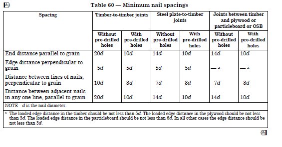
No you also need something at the bottom to stop rafter uplift. The birds mouth needs to be held in close contact with the wall head / lintel. You could maybe use a truss clip but on the outside face of the lintels. Will be nicely hidden here, but you need to fix them before the sarking / tiles. If you want to go for a "sturdy" job use the 7090's all over.. but some of the nails will be to close to the joint between the double lintels.. nail edge distance. You best bet is to assemble is and do a trial fit with the 7090 brackets.. use common sense.. do they look right if not try a truss clip. Generally a truss clip has 6 nails into the lintel / head binder and 6 into the rafters all with at least 19 mm edge distance for the nail in the loaded direction of the force if using a 3.75mm diameter nail... 5* 3.75 = 18.75mm ish.. Now that is quite hard to get right on site when you have angled timbers resting on a say a head binder. Have copied a table from BS 5268 for reference. But if you fit say truss clips on the outside the problem often "goes away"
-
Thanks Andy.. given me food for thought.. every day is a school day.
-
You are quite right. I expand. Firstly an appology.. My choice of wording lacks substance not least. With hind sight the use of the word "flair" .. wrong word to use as it sounds demeaning.. that was not my intent, far from it. Yes I do. But some jobs.. say knocking down an internal wall to create an open plan space are very much my bag.. SE.. not an Architect's as I have enough experience to deliver good design right the way through to completion.. I wear two hats and I have studied hard to be able to do so.. yes Architecturally.. the lines get blurred here.. but if you want to argue the toss I would say I'm just as well qualified to do that type of job as you as it is about the project holistically? Look at the other side of the coin.. you have loads of experience as an Architect.. I bet you can design a house / structure that will stand up structurally and be safe.. you just need an SE to "stamp" the paper work. I work with Architect's who I would quite happily trust to design my house with no input from me if I was say unwell. The two professions cross fertilise.. why can't an Architect use judgement to design a safe structure? For thousands of years they have done pretty well at it without SE's @ETC I'm fortunate to be able to work with Architects who are very talented, some are ageging but they are the best folk to work with as we just gell and focus on design rather than having a pissing up the wall competition.. about our titles.. that is good for the Client and we all like to work together.. the Client picks up on this and feels they have a team that is genuine... and that is partly why I'm booked up with work well into next year. For all.. Architects ..one of the reasons is that it takes a minimum of seven years study and hard work plus a lot of luck to even be considered for your Architect's chartership. Architects don't just draw stuff and wear sheepskin coats (although they are.. these coats as my wife tells me are coming back into fashion.. hang on to that coat ETC.. my fatherinlaw has one.. have my eye on it! ) they also know about contract law.. have a deep knowledge of the building, planning, fire regs, legal expertise.. land boundaries and a whole load of other stuff... long list. @ETC I'm definitley not knocking Architects, As an SE there is mutual respect so again apologise. There are indeed bad Architects, but some truly awful SE's who just don't communicate with their Clients in an reasonable way and just get stuff wrong. To finish. Rather than use the word "flaire" what about "art".. Our SE profession is often described as an art and science of design.. Architecture is the same just more emphasis on the art? There is no doubt that an Architect can bring something to the table that others do not have... be that design skills.. innovation, sage advice.. and in the round they may save you money, design you a house that you love, can sell on and make a profit.. For all and for me you need to find the designer that suits you and that requires a bit of leg work.
-
Learning to render external walls
Gus Potter replied to OllyIB's topic in Landscaping, Decking & Patios
Hey that looks ok.. seen a lot worse.. looks like you have something to work with here. Firstly the perpendicular joints at the bottom.. are they open and do you know how the wall is drained at the back? You'll get loads of folk chipping in on BH.. the more photos you post the more info / suggestions you'll get. The length of the wall looks ok in terms of retaining the soil as it has some good returns to brace it. If you want to finish it yourself I would start with the steps. What do you want to put on top? Could be slabs or at the high end a porcelain tile? Next is the risers to the steps.. how do you want to finish that? Then the copes at the side of the steps any thoughts? Is BC involved? Do you need a hand rail as the change in level is more than 600mm? Once you have nutted that out then turn to the render... that is the last bit. Any copes need a good drip so they need to be at least 40mm wider than the wall on each side.. after any render. I'm sure @nod will pitch up with the best solution. Main thing here is to sort the drainage behind the wall so you don't get frost blowing off the render. Once you have nutted out this then yes you could render it yourself.. but it takes a bit of practice so it may be that when you look at all the other bits it's worth getting someone else in to make it all a top job.. the money lies in finishing the steps and the copes / maybe hand rail. I think that is where you could learn to do it yourself and save the money.. one step at a time.. where as rendering.. you only get one go! -
Interesting question.. Gut feeling is you need to study the regs in detail.. and also refer to BS 7671 .. IEE the wiring regs and the safety regulations. Personally I would avoid it like the plague.. as soon as the power goes off you'll need to reset them all and BC I think will have something to say about that. I get the home automation thing but remember you may wan't to sell your house later to someone that is less tech savvy.
-
Learning to render external walls
Gus Potter replied to OllyIB's topic in Landscaping, Decking & Patios
Post some photos and you'll get a lot of help / guidance / suggestions. -
Advice re Chapel new build
Gus Potter replied to lakelandfolk's topic in General Alternative Energy Issues
Pile in folks, lots of folk on BH will be happy to help. To get the best out of this then it all starts in the ground and you work your way up from there. If you can post more info then will be happy to chip in with what I know as I'm sure others will. -
You have hit the nail on the head there. If you are an SE you are responsible for folks lives.. if some goes badly wrong you could kill a lot of folk. @saveasteading If you are a Civil Engineer and your dam fails falls down you could kill thousands. Yes you carry responsibility.. and it can keep you awake at night to say the least. That said there are a lot of checks and balances. The very first thing you do is to ask yourself "does it look right" if not it is probably wrong.. that takes experience. If you are on BH and asking a question as it may not look right to you.. then on balance you are probably right.. I encourage everyone to ask. Sometimes the question from the "lay person" is vital as professionals can get locked into a way of thinking and.. subject to "commercial pressure".. That simple question could save the day! That is part of the checking and balancing process. There are many more so if you have a good design team (that includes you) there is no reason to loose sleep. So to all on BH.. keep asking questions!
-
My own view is that much depends on experience, knowledge and demonstrable skill. I have worked with some SE's that I would not let within a country mile of my own house! I work with an Architect that has been at it for 50 years.. he designs stuff and I say to him why do you need me? .. he says.. for the SE paper work young lad! Then you have all ground in between. I think the secret it to work out what you need and find someone that can do what you want and have experience to say.. hang on.. here is a bit of friendly advise, I'm invested in your project.. let's not drop a clanger.
-
Hi Mortar. Have not checked you figures as kind of off duty here. These brackets look like a Simpson AE35. You have to wrap the top tab over. Your train of thought is good. You mention wind.. probably won't govern unless it gets close to a mansard type roof which you don't have. It's the practical side of things.. on a loggia folk will pile stuff up and use the posts to hold it all still.. that is where the risky horizontal loading comes from. I would stick to the 7090 brackets. Other way it to use ceiling ties.. but that compromises the vaulting effect to some extent. As an aside for all on BH. If you have an add on to the house with one side open and the rest clad you can encounter quite a lot of horizontal wind forces. This is what we call an open sided building.. has a dominant opening. You find this with hay sheds. In the spring you have the columns, it is just empty (hopefully) and the wind blows though. But say mid winter.. the bales are left at the sides and taken from the middle.. the wind blows in and can't get out the sides so it lifts the roof off for example.
-
Top response from @George Agree. Will do no harm to ask. To provide a bit of background. I started out as a building contractor, got interested in structural design so went to uni at forty to study structural engineering. Served my time training and now work as a sole pratitioner as a Structural Engineer and architectural designer. To be a good designer you need to have experience and a flavour of holistic desgn. I make a living doing what I do. Designing extensions, attic conversions, barn conversion, some steel buildings, some industrial, the odd new build, bit of ground works, garden buildings.. long list... it's a fun job but with responsibility... no free lunch. Now I think I do a good job.. but I do get some jobs that require the flair that only an Architect can bring. When this occurs I call up my Architect pals and say.. this job needs YOU do you want to collaborate? It is the sensible thing to do for me. I'm not a bad arctitectural designer but I know my limits. I know from years of experience when to call for help.. swallow your pride and this delivers a good project.. you learn from it and this makes you a better designer. That said I make my living wearing the two hats.. it is a competetive business this building malarky! In terms of insurance. From talking to my Architect pals I carry a lot more PI insurance cover under my SE policy than they do... in fact significantly more and as @George says I'm quite happy to provide the documents if asked. But.. I don't make a point of it when touting for business.. after all you are saying to your Client.. hey if I cock it up I'm well insured.. the point is you DON'T cock it up! My SE cover also covers me to do the architectural design and spout my thoughts on BH. In summary though for all on BH. The best thing you can do is research. Some folk on BH have loads of experience, know what they want and just want someone to produce the paperwork to get BC approval and check it won't fall down. Others are just starting out and maybe need someone who can guide them.. hold their hand while they cut their teeth on their first project. Yes it is ok to use an architectural designer @TryCbut make sure you do your due dilligance.. take references from past Clients and so on. Try and find someone local to you that can nip round once the project is underway and check on the builder. The main thing it to find the person that suits you and you gell with. Then explore what they know and what they can do for you. If you have put in a bit of ground work you'll soon know if they are up to the job or not. All the best with the project.
-
Steel to support a garage door
Gus Potter replied to puntloos's topic in New House & Self Build Design
Hang on! I may be over thinking but my first reaction is.. the 203 UC columns and beam are probably working to provide part of the horizontal stability stystem to the house. Easily over looked but critical for safety. Can you post more of your plans. Also post if you can the connection design between the column and beam as this will give a clue as to what the columns and beams are intended to do. Please don't swap these out until you check with your SE. -
Stud wall spacing options & ply faced studs?
Gus Potter replied to ruggers's topic in General Joinery
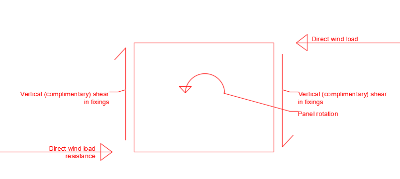
Unfortunately it often partly ends up that way, a non load bearing racking wall can catch you out. Advise you stick with your SE's specification. In written form you have a timber frame panel that carries no vertical load but it needs to stop things moving sideways. Say the top of the panel is loaded horizontally. This horizontal force gets transferred to say the floor below that resists the horizontal force. Now you have two forces acting in equal an opposite directions but they are separated vertically. This introduces an overturning effect into the panel. We call this a complimentary shear force. The static laws of physics say that for a body to remain still every force has to have an equal an opposite force. Thus even though your panel is not carrying a vertical load.. only a wind load the vertical fixings at on side will be subject to uplift and at the other side a downwards force. That is why you may wonder why your SE has come up with what may seem an onerous spec.