Gus Potter
-
Posts
2341 -
Joined
-
Last visited
-
Days Won
29
Everything posted by Gus Potter
-
More foundation fun - straw bale garden room on clay
Gus Potter replied to Nick Thomas's topic in Foundations
Well done having a go at this. Unfortunately it's not a simple task... I can see you have had a go at calculating the sliding resistance. Call this the global behavior of the structure. I have not looked at you calcs in depth but you are missing two vital things, the first is factors of safety, second and fundamentally when the wind hits the side of the building some goes round the sides and some over the roof. But there is already wind over the top of the roof so you need to squeeze this extra air into the envelope around the building. This increases the air velocity and particularly a flat roof starts to act like an aircraft wing and the roof lifts up. The uplift forces are large so you need to deduct this from the self weight of the structure. Now normally the sliding check is fine and not the critical check as say masonry structures are heavy.. bales less so. The structure could also hold together and overturn.. roll like a ball. My gut feeling is that even with a bale building this will probably not be the critical check. What I think will be the critical check it to make sure that the columns you are forming on the front elevation are able to carry the wind loads as individual elements. Around the sides of the door and at the corners you could get very big uplift forces.. unless you make the roof very stiff. In other words I think that even on a windy day the front wall will start to skew sideways (you also need to transfer what are called shear loads and the bales I don't think will do this well).. then you won't be able to open the doors... take this as an early warning you have got it wrong. To sum up the above. Wind loading is complex, there is a lot to it and the knock on effects are significant. For me.. you have a limited life structure, not occupied all the time.. you could compare this to an open sided farm building in terms of sideways stability (your front elevation with windows / doors), a marquee or similar temporary structure. When we design these we take a more pragmatic view, settlements are less important. What we say is we need to stop two main things happening. The first is that it does not suddenly collapse (without warning) and second is it does collapse say in the wind that bits don't fly away and hit people first and then other buildings ect. I think you really need to stop the front of the building moving sideways and will struggle with bales. One solution that springs to mind is to make the frame around the doors very stiff and strong so it resists the sideways forces. We do this when making big openings in the walls of buildings that are intended to hold things up and stop the building moving sideways. You door frame could be a portal (two columns and a top beam very well connected together) or a box frame, I think this may be best to look at first... the box frame You could make the structural door frame a feature to compliment your attractive design? To get your head round how the sideways forces work make a portal or box model out of 3 or 4 members.. bits of wood. Hold it at the bottom and push it sideways and see what happens. Look carefully you'll get a downwards load at one side and an upwards load at the other... this uplift load is the dangerous one! This load needs to be resisted by tying down. Encouragement! I bet there are loads of folk that would love to be able to do what you're doing and can see you are making a great effort. If you can do this for 3 -4k materials folk will chew your arm off! One way of really understanding this and how it will roughly behave is to get a cardboard box (or a few), cut holes in it to the scale of your windows / doors. Make a roof for it and pin / tape it with match sticks ( to represent your Hazel sticks) to the top of the box. Tape the thing to the dining table and start to push it sideways.. see what happens. This can be great fun for both adults and kids.. before you test it to destruction observe it first or you'll use a lot of boxes! This might sound a bit daft but this is how we teach SE's! Keep posting! -
Yes at the moment, as others often point out 1kW of electricity into an ASHP for say 3 -4 kW out.. depending on the outside air temperature but as gas is say 1/3 the cost of your electricity it ends up roughly the same. @Fallowfields you have probably thought all this through but for me if you are rural then I would look at your location and altitude. For example my sister lives on the island of Tiree. Here they benefit from warm seas relatively speaking when say compared with the North sea off the East coast of Scotland or say the sea off Newcastle / Norfolk. They also get a lot of wind. The air temperature never drops that low, say -4 deg C but even then only for a short period of time due to the warm sea all round. They have two ASHPs that really deliver, are economic to run.. they are delighted with them. Reports are that they never hear them having to work that hard, in other words a big drop in efficiency. But as they are rural.. well very the electricity can go off.. no heating and no hot water. The house is well insulated, pretty air tight and they have a gas hob run off bottled LPG and electric ovens. They actually find this cost efective as the hob uses not much gas although catering for a good number of people most days. They also have a wood burning stove. In other words the house has some redundancy built in. Before committing to ASHP I would have a look at your location. If say Wales / North Scotland at 250 - 300m + altitude then you could experience several days where the temperature is below -10 to - 15 deg C.. and regular days when the temperature stays below zero C all day and drops further at night.. what then and what if the electricity goes off? I'm not saying don't put them in... just that your location may influence the overall performance. You other option is oil fired boilers.. but I think their days are numbered (I had one in a self build out in the country and at that time it was great, oil was cheep and it ran a UF stystem over two floors of the house) in the sense that the oil is delivered by companies that don't often play fair and as demand for them drops off then probably the maintenance cost will go up and the oil price will also likely go up. Maybe in ten years time you'll get you oil delivered by an EV tanker? You could maybe set up you system so it can an easily take an ASHP later, use a cheep oil boiler and tank to start with and wait for the price of ASHP's to come down? It will impact on your energy performance calcs so you may need to add more insulation ect to compensate.. but that is no bad thing. Of course if you had a big plot you could have a ground source pump.. ideally a stream / burn with good all year round floor or right next to the sea so you can extract heat from that... but few of us are that lucky.
-
Planning are insistent on a dormer
Gus Potter replied to Fallowfields's topic in New House & Self Build Design
Like your idea here. Good luck and let us know how you get on. -
More foundation fun - straw bale garden room on clay
Gus Potter replied to Nick Thomas's topic in Foundations
I think it's a great idea @Nick Thomas as a project to do on a budget of 2.0 k.. quite a challenge for the walls and founds, with the roof extra over. Have not dug out my book on bale building but keeping the water out of it is a biggy. That means things like a big eaves overhangs to shelter the top of the wall and mitigating spashing up of rain.. @Nick Thomas mentions 300mm to the bales which is well above a normal spash zone. Also you want to get plenty wind circulating round about to dry things out.. not sure about how close it should be to the retaining wall for that reason. The vertical loads on the bales are not huge.. they will compress over time but it is not like a house designed for 50 years with more onerous loading from say floors, tiled roofs. If it was me I would make sure if the bales start to misbehave then devise a way you can prop the roof / jack it and insert a more traditional timber frame instead so you don't lose your shirt or do the bales again.. tricky as they need to settle in as you build. Normally a garden building like this could cost 15 - 20k (if you went to a turnkey outfit) once serviced with the slabs outside / drainage etc and that would be for a square box. But here we have a bit of character in terms of the shape and form.. and for that you could pay a lot more! Keep posting Nick! -
More foundation fun - straw bale garden room on clay
Gus Potter replied to Nick Thomas's topic in Foundations
Well done for giving this a go, thanks for posting as very interesting. Fair enough the walls are light in weight and I assume so will be the roof. How are you going to tie it down to stop the roof and walls lifting up in the wind? Are you going to use the long spikes to pin the roof wall plate down a good bit into the bales? Bit of house keeping on the maths mainly for all in case they use the same sums. 5 tonnes = 5000kg. Convert to Newtons 5000 x 9.81 (just say 10) / 1000 = 50 kN (not 5). If you have 2.5m^2 of pad area then roughly the pressure at the bottom of the pad will be 50 / 2.5 = 20 kN/m^2. If it is a temporary structure (say snow loading with a return period of 20 years as a ball park figure add some 0.35 kN/m^2 to the roof loading unless you are at a high altitude UK wise. A good bit of that soil you see next to the wall will be backfill (made ground).. ask how are the founds for the retaining wall formed. How far do they protrude into your garden? Is the soil you see just well compacted fill? The main thing here to watch out for is that if you are digging next to a retaining wall is that they are designed for two main things. One that they don't tip over and two that they don't slide into your garden. The sliding is important here. The sliding forces are resisted often by the friction under the found and also by the soil on your side and this can make a big contribution towards sliding resistance. I would avoid disturbing more of the soil close to the wall on your side or lowering the ground level on your side close to the retaining wall. I would give the OSB a swerve as I have my doubts about it performing well in this application.. it is thin and you have fixing issues.. and any long term moisture is not good for it. What about using cheep fencing slats with some 3 -5 mm gap between that are treated, these are more breathable than say OSB? Anyway it keeps the ethos of using more natural rather than highly process materials (lots of glue) such as OSB. If you have doubts get a bit of OSB and leave it out in the rain / in a bucket of water for a while and see what happens to it. As the thing is light weight how are you going to stop it blowing over sideways in the plane of the retaining wall? I assume you are going to make the roof like a stiff beam that transfers the sideways wind load to the rear wall? In high winds you could easily get 100 kg/m^2 wind uplift on the roof unless you live in a very sheltered spot. At the same time you get the wind blowing on the sides of the building wanting to push / suck it over sideways. I think it is these wind stability issues you need to concentrate on rather than the founds, although they are important.. settlement won't generaly hurt anyone (unless left unchecked) where as the thing collapsing or bits blowing off and hitting folk in the wind is a concern. -
What insulation for 38mm service void in MBC passive wall
Gus Potter replied to markharro's topic in Heat Insulation
No the spark won't and you are heading for big trouble if you start to insulate cables that are designed to be in a void for example. Your spark will have carefully sized the cables based on if they are in a void or have insulation close. You are now adding insulation on a whim. This is very serious and you need to talk to your spark. I have seen fires occuring in extensions to houses as a result of design changes like this... the house down the road from me went on fire for this kind of reason. Your other designers (and that now seems to include you as you are making technical design decisions) should be alerting you to this.. or do they not have enough experience and that includes you too? Now I may seem like a bit of a tosser but if you are making design descisions like this and you get it wrong then your insurance is invalid and the rest of the design team will probably leave you carrying the can! In summary I can see you are enthusiastic about what you are doing .. which I very much appreciate.. but you probably don't realise that something that seems innocuous (you are tring to make the house warmer) can have a dangerous impact. Now if you don't believe me about the wiring implications.. have you checked if what you are doing is going to shift the dew point in the wall and do you know what could happen if you do? .. you won't probably significantly but I say this just to make a point. I laid it on thick above but for your own safety.. give the spark a call on the phone.. if you don't then there may be no electrical IEE completion certificate from the spark.. and that is often a problem. -
True to you word! Excuse the spelling, quick response. Visually your soakers don't have enough upstand.. but I think you'll get away with it as the roof pitch is steep. I would recut the top line of the chase. Put a timber batten up the line of the roof, put safety boots on and hold the batten with your knee or get help to hold it at each end.. the easy way and much better, and recut a few mm higher with a 9" grinder with diamond disc, marked for depth of cut. Aim for 25 - 30mm depth of cut into the wall. Get your top side of the chase straight. That is the bit you will see. Get a brush and clean the chase, then get a Henry hoover / Dyson and really get rid of all dust from the chase. I'm not joking! Go to B & Q and get some SBR bond. Apply the SBR bond to the bottom of the chase only. Follow SBR instructions, let it go tacky.. if it dries out it is no good and makes the bond worse! Don't get the SBR bond on the slates and clean your tools pronto after. Cut the batten down to 25 mm less than the depth to the top chase. Hold it against the wall. Make up a mix of 1 part cement with 3 parts sand with some mortar plasticiser. Use the cut down batten as a guide to re level the bottom bed of the chase when the SBR is tacky. Clean up, keep it moist and go for a beer and let the mortar harden for a few days. Now you have a neat top cut and have sorted the bottom part of the chase that you need to be able to jamb the lead into the rebate. If you leave low spots in the bottom chase the water will get back into the wall and the flashing wiil get distorted when you are trying to fix it in place. If doing it DIY fold up your flashings but keep them to 1200mm long in length, then install as per Cookson Lead work guide. Be gentle when jambing the lead into the chase.. then point up and seal the chase. Make sure you use Patination oil and apply it to both sides of the lead (the bit you see and the bit you don't) and edges of the cut lead. This sounds like I'm laying it on thick but you have some good looking stone and slates there.. don't spoil it with crappy flashing work. In this case I would say the flashing should stop 10 - 15mm from the top of the slates.. stops capilliary action. As the soakers don't have enough upstand then just along the top of the soakers run a V shape line of lead mastic at the top edge. You can do this V by cutting a slot in a standard matsic tube nozzle. Ths will create an extra ledge which will mitigate the lack of upstand depth of the soaker.
-
Cracks showing under first floor landing
Gus Potter replied to jayc89's topic in General Structural Issues
Yes it could just be seasonal movement. Often folk see cracks and think "oh no the house is settling and going to fall down" in the next week. Observe the door over the landing and see how it sits in the frame when shut. Often if things start to drop then the doors start binding. If you want you can cut thin shims out of say a coke bottle and monitor the gap to a reasonable degree. If you can slip in 5 shims and a week or two later you can't then you can get a feel for how things are moving. You may find that once you put the heating for a few days the shims come slack. If the weather has been dry and warm then turns wet you should be able to detect that in the shims. This will give you an idea of how your house behaves on an almost week to week basis. You'll be surprised just how much things move, but it can also set your mind at rest.. it's just the old house doing what it does. To provide a bit of context. The major house buiders are tackling more and more difficult sites with less than favourable ground these days. They improve the ground, often by soil mixing using lime / cement etc. The new houses are designed not to settle more than 25mm over 50 years so even on a new house you can expect quite a lot of potential movement in the first few years as settlement is often not linear. Bonner makes good points. If you try the thing with the coke bottle shims let us know how you get on. Make sure you use don't mix the shims up.. keep them all together in groups for each gap, use tape to keep them together if need be (they are a cheep version of feeler gauges but not calibrated) or this could start to live in your head. The nice thing is that they are pretty flexible so can get round the odd bendy bit of wood. On doors push them in until you hit the door stop so you maintain the depth of penetration each time. -
That would help, lets us see what you have on your plate.
-
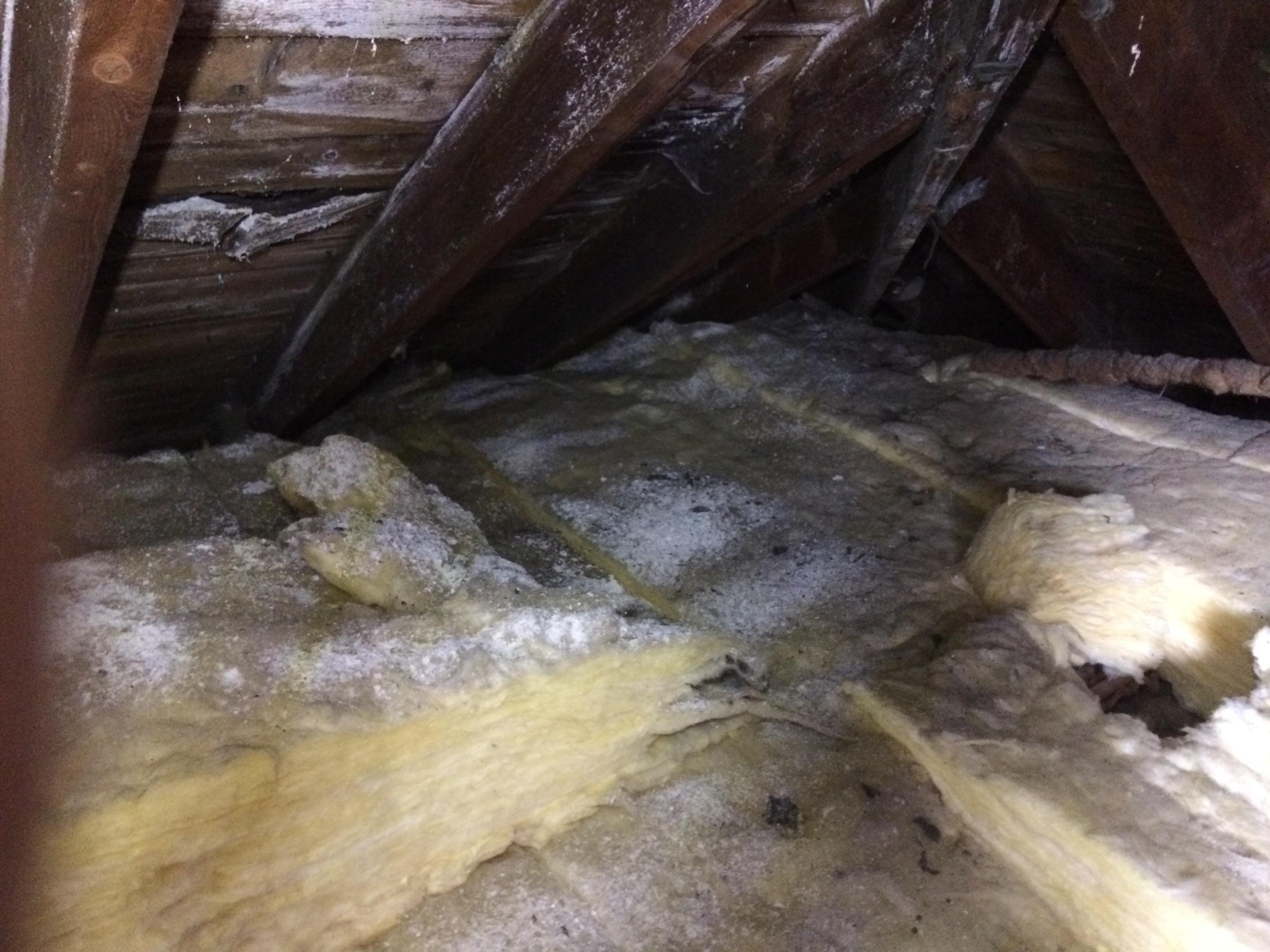
Thank you everyone for giving me the benefit of your advice. Very much appreciated. Looks like some type of white mould. Will get it checked out and also check for asbestos just in case. Thanks again folks.
-
Planning are insistent on a dormer
Gus Potter replied to Fallowfields's topic in New House & Self Build Design
Yes that can work. If you do hips.. it does soften the roof. Well done you sorting that out. You can do a Dutch type hip.. but sometime SE wise they are "hard to do".. but there are work arounds if you want to preseve the floor space in the roof.. you can do some cranked steels for example if you have a big house and have plenty money... that said it works fine in say in Surrey ( added property value ) but less often in regional parts of Scotland or Wales. -
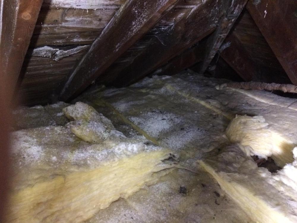
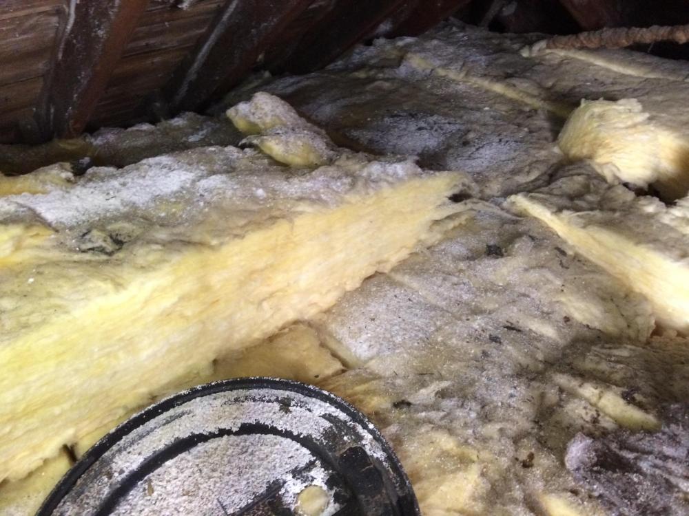
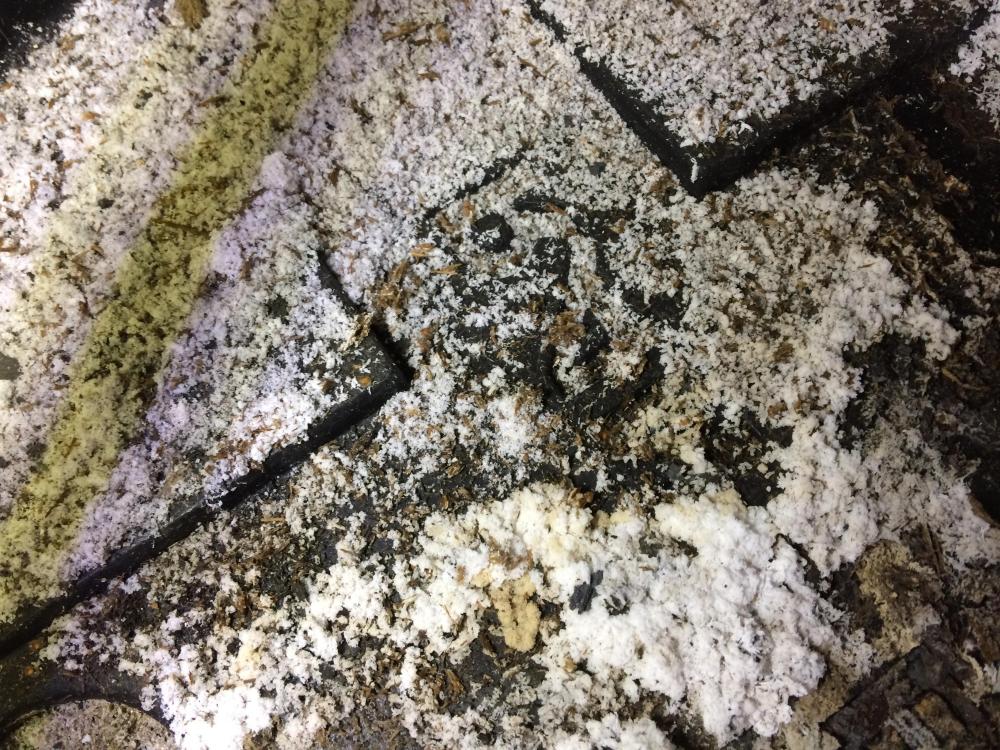
Thanks for chipping in. I need a bit of help here to understand what I might be seeing. I was wondering.. am I missing something that is obvious.. sometimes you can't see the woods from the trees. That is a good point. To be honest I touched the residue on the plastic lid (then followed all the safetey protocals) It felt like salts that you would get growing out of say masonry. It was like a powder, and not binding together and not gritty fealing. The thing is that there is a lot of it Could be rot but there where no indications of mycelium growth and the assocaited root propegation or fruiting bodies either dead or alive. The roof timbers all looked sound. Yes in relative terms.. the thing for me was that the plastic cover that was lying about had it on top.. so I think it can't have come from below. I have seen lofts where there is snow type stuff lying about but that is often when they have had cavity wall insulation installed. This looks totally different. I'm stuck to identify what this is? If the Asbestos folk come and test it then they may say.. no asbestos. But my Client has young kids so if it is some kind of chemical I can't take the risk and I can't expose the Builder to the risk either.. I have seen what I see and professionally I cant "un see it"
-
Planning are insistent on a dormer
Gus Potter replied to Fallowfields's topic in New House & Self Build Design
Ok to go back to the original post and what @Kelvin is discussing. The process at our design end is logical. Your starting point when you encounter problems is to review what you are doing. You look again at what is within you permitted development rights and identify where you are breaching those. You make a list of the breaches. I know it is a new build we are discussing but I always go back to the very beginning on every project and review what we know and PD rights form part of that review. Next you look at what is round about in terms of what has been built. If you live out in the country it's different from being in a town... but you still can't have a crap design that looks bad. Ignore the technicallities for now, just look at what you see and how different things have been introduced to the built environment. Use your eyes and remember / photograph what you see. This is important as it will form the basis of a planning application... it will also help you to not build a house that does not fit in.. think .. who wants to buy a house that does not fit in? Think about when you come to sell. Is a surveyor going to clock that too and reduce the value? I mentioned massing earlier (too much of one building element for example that dominates the overall look) but there is another aspect to this which is proportion. The different elements need to be propotional to the rest of the building.. your common sense will help you a lot here. If you think about it.. at the moment you want to maximise space / reduce complexity.. but in a couple of years time you may come home and realise that your house looks ugly. Another thing is how you use and introduce different materials. You could for example build a new house that has a part traditional farmhouse look and then add on an "annex" with say a Zinc roof and timber cladding. You may find examples of this locally where you have old 17 centuary houses that have modern parts added to them. Here what we do is to say.. we have the old and "a distinctly different but complimentary style". What we do here is to say.. we are appreciating the traditional design but adding something more contemporary but sympathetic to the 17 centuary ethos. I think you need to do more work on this and look at it in the round as your forever home? If you do this then there is a good chance you'll get what you want within you budget. Now if you can satisfy the above or something along these lines then you stand a good chance of getting the planners to agree. -
That is the reward spelled out in a nutshell. You get a very deep and long lasting satisfaction from it, you don't need to broadcast it as others can see what you have achieved when they visit.. your hard work will speak for itself. You just know you have done something few folk can do. It is your castle, home and unique.
-
That is amazing that you managed to do that. One small stone and the game is a bogey. I do wonder what your house is sitting on? For all, if you are not as lucky as @JohnMo you can sometimes use a steel plate buried in the ground as this gives you a big surface contact area. If you plan ahead you can use your strip found (steel piles give a good earth) to give you an earth in poor conductivity soils. Here you pour your founds but make sure the layers of reinforcement mesh in the found are electrically bonded. This gives you a big contact area with the soil, much more than a earth rod. The steel mesh in the found is protected against corrosion by the concrete. If you get the spark in early they can test to see if you have continuity all round the found. Now if you tie your mesh in the founds together properly continuity should be no problem. This requires forward planning.. but that is another added joy to self building.
-
I think what you are doing is great. I love your enthusiasm for this and in general. You are testing my knowledge which is great for me, appreciate that.. a big thanks from me. As primarily an SE it is important for me to be able to distill sometimes complex things into language that folk on BH can find usefull. Here are something other things to ponder on your drive. You might want to explore using solid timber flanges top and bottom.. basically copying an engineered joist.. but they often use laminated timber. This will simplify the design. You router out a slot in the timber and fit the web into that. I think you will get more bang for your buck this way. Next is your glue. Have a look at Cascamite glue which is a proper structural glue. Lastly for now if you can get a hold of an engineered joist off cut and split the web from the flange you'll often see that the web is slightly tapered so it jambs into the routered slot in the flanges. You may get a fright as often the web departs from the flange easier than you think! But your idea of using the timbers to connect the web to the flange also works.. but it is labour intensive and will need a a lot more thought to get something that is reliable and consistent in terms of how it is put together and has no weak spots.
-
Good question. Yes, new builds partucularly in Scotland have a more onerous set of regulations in terms of compliance. In terms of cost here is something I do. I have a Client who is a property developer. They target bungalows at the end of a street. There are a lot of streets in Scotland that have two storey houses with bungalows parked at each end. The idea was that you had families living in the two storey houses and the granny / grandad lived in the bungalow at the end of the street. Last week we looked at one, this threw up 4 initial options that ranged from renovating, extending side ways and upwards, splitting the plot for two houses or doing two semi detached two storey houses. My Client is going to make an offer next week on the property. Now the demolition and rebuild option saves the vat and potentially there is money to be made if we build new... but that carries a serious planning risk and there is a delay factor when dealing with planning. To be sensible we look at.. can we make money / at least break even by renovating or extending sideways.. that is the back stop position.. you don't want to loose you shirt. If we get the property how hard a fight are we going to have with the planners and what are we going to find that is a risk (as an SE I know there is a bit of a settlement problem in this area for example).. on the upside once we get our hands on it we can then decide what to do. To answer your question.. each project is different so there is no difinitive answer. I would interrogate your Architect / Builder further and make an evidence / risk based decision. The BC regulation compliance is probably further down the list. Funnily a lot of the building regs are really good for you and help you get a good quality house that will hold it's value.
-
"The mathematics of it are pretty simple." I have a graps of basic statistics and probablility but you have the edge on me here. That said I can follow your first paragraph and agree with the thrust of it. "It is the interpretation of the results that is important." Absolutely.. it's like using finite element analysis.. manure in manure out, and all models must be verified but manual fag packet calculation. "So I could design and build a set of identical beams, some for my shed, and some for a new roof on my house. They would both do the same job and be subjected to the same loadings. But the ones on the shed, if they did fail, would have much lower consequences that the ones in a new roof. So to be safe, SEs allow for this and do what @joe90 does, over engineer." No, SE's are not that blinkered and you mention the consequence of failure correctly. Your shed could be treated as non habitable building. If could be treated as an Agricultural type building with low occupancy and say a 20 year design life. If so then we reduce the loading (quite significantly) based on say a return period of heavy snow and a reduced roof access load for maintenance. Houses are mostly designed for predicted loading that could occur over 50 years, Agricultural buildings can be designed on a 20 year snow event for example. Also on an Agricultural building we have often slacker deflection limits as we don't have internal brittle finishes that can crack, doors jamb and so on. If you are going to be designing beams for your house then be careful.. and remember that if you sell someone may ask you to to prove all is ok! If you experiment and gather data on your beams then you could have the same size of beam you have investigated but longer spanning for your shed as the loads are reduced and the deflection limits less onerous. Keep us posted on your experiments.. it lets folk see on BH how these Engineered joists work, the plus and minus points and what you are doing kind of removes this "mystification" where folk are trying to cost up the things.
-
Planning are insistent on a dormer
Gus Potter replied to Fallowfields's topic in New House & Self Build Design
Post some photos of what you have round about and your proposed front elevation. They may be getting hung up on what we call massing.. the roof area looks too dominating and they want it broken up.. but are not actually telling you what their issue is... and this is really common. Once you understand why they are pushing back you can look at your options. You may find that down the road there is the odd Dutch hipped roof.. that softens the angular shape and the massing effect. Also do you have a chimney? these can be used to break up a roof... even if a false one... I know you want something simple and not prone to leaking. but just a thought. -
Is the water table low and the sand bone dry? Did you actually drive one spike in 9.0m? If so is your house on piles or something?
-
They are. On BH there are plenty folk who have done their research and have a good idea what they want already. If you get your Architect or SE in early then they can do almost a watching brief, give you the benefit of their knowledge and sometimes say.. are you sure you want to do that?.. have you thought about this and that and here is a better way for you to consider. I often say to my Clients, (sometimes they have firm, almost entrenched views) see some of the ideas I come up with.. you won't like them, but that is ok as it's part of the design process and don't be afraid to say so. But on occasion they may say .. we never thought of that! Good design often means at the start throwing everything on the table, most of which gets ruled out.. then you concentrate on maybe one or two options and develop that further. From time to time I work with a QS if the Client wants more certainty, but like all things that comes at a price, and as @Kelvin etc have said not all QS's are briliant! As a designer I most often work on a fixed fee. My fee is built up between my Architectural input vs my SE input, two different rates apply depending on the mix.
-
Then by intuition you should get a bit of velocity behind the flow to clear the short 600mm run. Crack open the beers and have a long lie tomorrow.
-
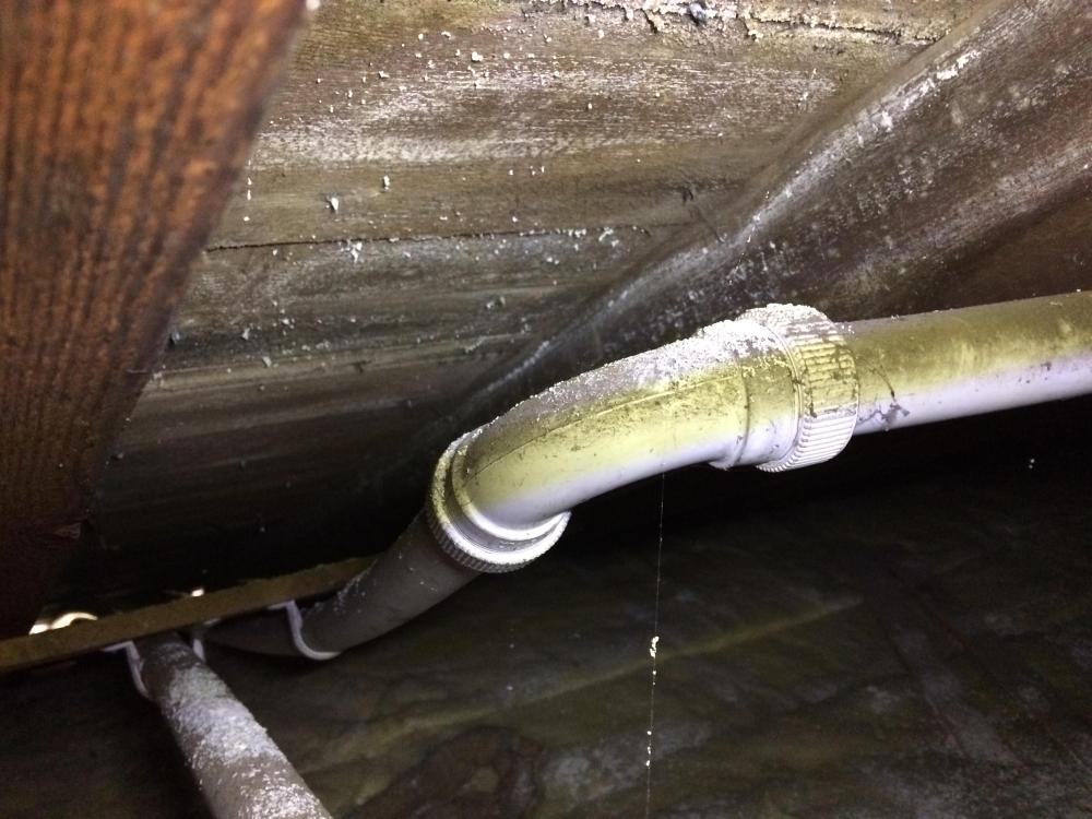
Has anyone got any ideas on this? I have a project; two story semi detached house built circa 1935 with a sandstone exterior skin , probably brick inner skin, no cavity thus it has solid walls externally, internally a set of brick load bearing spine walls. Roof is traditional cut timber with sarking boards. The non load bearing walls on the first floor are lath and plaster on timber studs. What I'm doing is demolishing a load bearing internal wall on the first floor which holds up the attic floor joists thus I need to put in a beam and some other structural support. To intall the beam requires disruption to the first floor ceiling which is attached to the attic joists. I know this about the building. 1 The Client has owned it for say two years. 2/ The roof may have been reslated/ repaired but this was a good time ago, maybe 30 years, possibly longer. 3/ The attic has been lined out but not a habitable space and accessed via drop down ladder. 4/ The roof was insulated with glass wool by British gas.. I can see their warning sign not to walk on the glass wool. I think British Gas stopped insulating lofts some 30 + years ago.. maybe wrong.. does anyone know? 5/ I know that old under slating roofing felts can contain asbestos and they were still used well into the 1980's. 6/ In the last couple of years the roof has suffered from significant leaks and the new owner, my Client has to get folk in to fix what they descibe as a couple of "floods" from roof leaks. 7/ There is no record in the title deeds of the roof having been sprayed for wood worm etc, but that does not mean to say it has not been in the past. 8/ The building has no cavities thus cavity wall insulation can be ruled out. As part of my survey and design I go into the attic and open a small door which lets me see into the roof void.. I observe the following. The above show a white residue on the underside of the sarking and on top of the glass wool. The above shows same residue build up on top of what looks like an old tank overflow pipe. The above shows more residue on the same glass wool but there was also a plastic lid lying on top of the glass wool that has residue in it. The above is closer view of the residue on the plastic lid. Usually I put big warning notes on my drawings if I suspect asbestos may be present, the age of the this house.. well it will probably be lurking somewhere. What I also noticed was that there was a small gap between the sarking boards, could not get good photo without disturbing the residue so stayed well clear. But I could see that through the gap there was some kind of sooty black fiberous material, don't know what it was but it didn't look like old bituminous felt... maybe it was just local.. I don't know. In cases like this I always recommend that an Asbestos specialist survey is carried out.. but I'm naturally curious and want to learn / expand my knowledge. The thing is the residue is quite a heavy build up, so maybe not asbestos... anyway Asbestos is not water soluble My thoughts so far on what it could be are: A/ Is it salts washing off the underside of the roof slates, yes sometimes you do get salts on the slates.. but never seen it this bad. But for this to happen the roofing felt would need to be seriously degraded? B/ The residue on top of the plastic lid means that the residue can't have come from the glass wool? C/ If the roof timbers have had a good soaking has the water washed out possible wood work spray. D/ Has loft space been sprayed and what I'm seeing is over residue from the overspray.. they must have gone to town with the chemicals? The thoughts of BH folk would be much appreciated.
-
It should be fine. I thought you were taking about something 2 -4 m long. The bath should empty fine so long as there is a bit of a drop between the outlet from the bath trap and the start of the 50mm dia pipe.
-
You have understood most of it. "load it till it breaks or buckles" What the calculalations and figures do is translate that into how you determine a safe design stength and how much it will probably deflect by if you then made this type of beam and built it into your house. When we design and test stuff it costs money so we don't test to destruction right away. We try and gather as much info on its behavoir before we destroy something. If you look at the load span tables for engineered joists there are loads of different figures for loading and span. The manufacturers don't test every combination. The probablitlity bit is to do with how many beams you test, like say a pull out test on a resin anchor. If you only test one then it does not tell you much. Test three and you can get a better idea of the spread of results. Test five and you gain more "confidence" and that lets you then reduce the reduction factor. Just call the standard deviation. This make the design more efficient. If you think about concrete many millions of cube crushing tests have been done over many years so there is lots of confidence about the spread of results you get when using normal concrete.