
Nickfromwales
-
Posts
31390 -
Joined
-
Last visited
-
Days Won
346
Everything posted by Nickfromwales
-

Underfloor Heating and Viessmann Boiler Set up
Nickfromwales replied to revelation's topic in Underfloor Heating
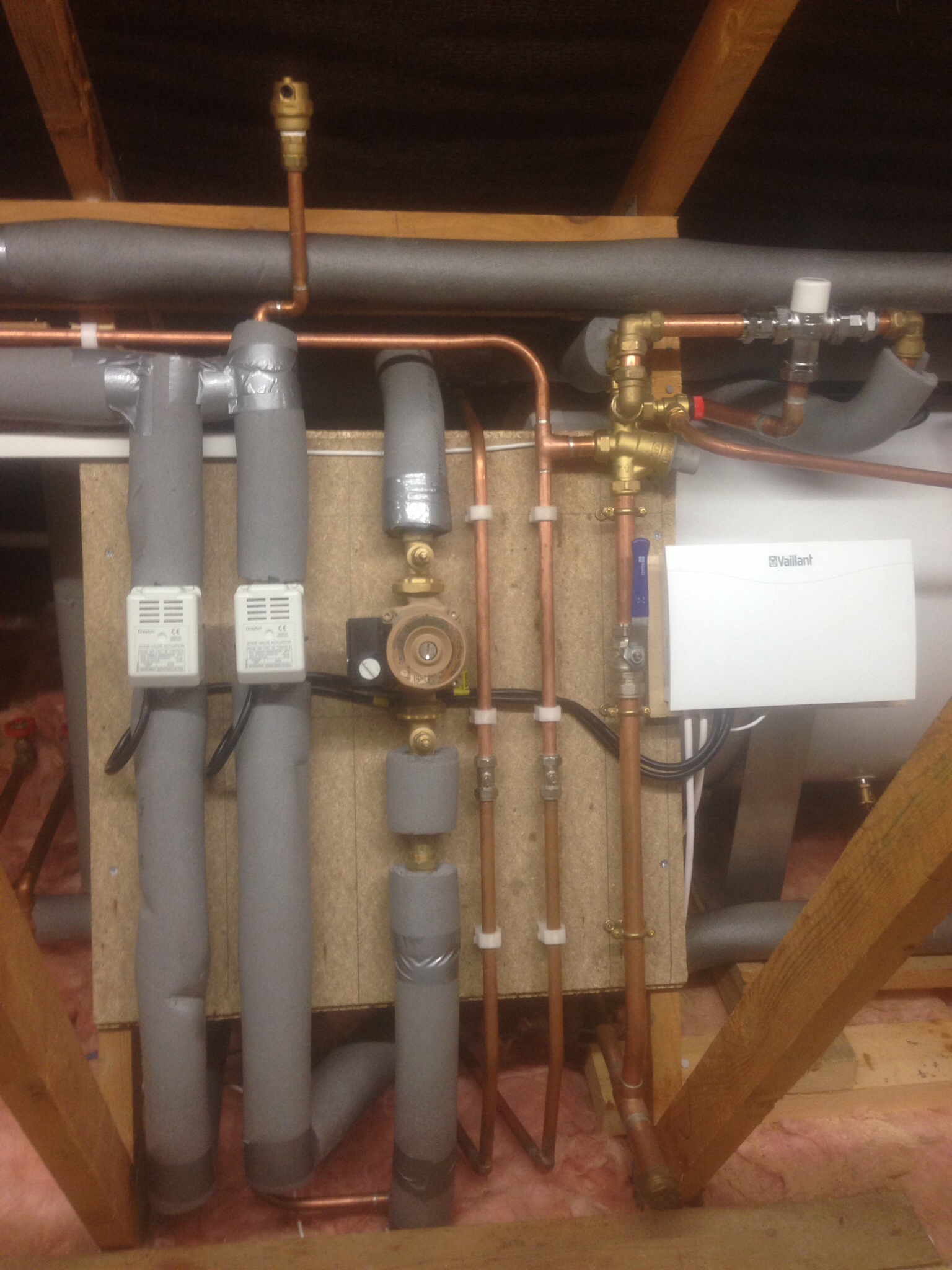
+1 on not bothering with WC’p in a well insulated, low energy dwelling. The house heating system and thermal time constant just cannot adjust linear to that being sensed from outside. I have it going on atm with a very high-spec Steibel Elton ASHP ( aiming for a CoP of 6 ) but will likely have to make WC’p defunct after commissioning as I expect it won’t cope with a PH. In a nutshell, yes, but you should set the flow temp just a bit higher if there is to be a buffer or low loss header. I have just been called to retrospectively adapt an identical setup to yours, and I installed a 50L wall mounted buffer tank which was used as an energy buffer, to absorb the heat from a single heat cycle eg to stave off short-cycling. Quick and easy job.
-
Where each screw head pops, clean the cross out of the screw and see if the screw can be tightened. If so, it’s a case of the fixing not having been driven home properly during the installation of the boards. I’ve done turnkey projects on both timber frame ( which have all gotten soaking wet at some stage ) and ICF builds, and none have had any more than the obligatory 2 or 3 screw heads pop. 16 is indicative of the board screws having not been driven fully home. FYI, it’s pointless fist filling over these, as the pops are caused by movement. Either tighten the screw before filling, or take it out and re set the screw 25mm away from where it can out to get a nice fresh bit of purchase.
-
Your accountant ?
-
The minority shall not create any detriment to the majority. This is an open forum for sharing information and advice for a crowd far bigger than 1. Rest assured, you’ll go unanswered by myself from here. ?. ”Focker, out”.
-
Mine is 6 devices with 100gb shared. Topping up if you run out is not done at a sympathetic rate…..
-
Yup. Then see the inclusive data disappear at eye-watering cost to replace. You’re gotten by the bollaux either way ?
-
We just forget how few trinkets we need to “survive” aka live perfectly well. Fitted a few USB sockets in mine on the weekend, WiFi had to go off for about 30 mins. I was lucky to have escaped with my life
-
"Load shedding" ( usually via a heavy current changeover relay ) https://searchdatacenter.techtarget.com/definition/load-shedding
-
ASHP + Buffer Tank Questions
Nickfromwales replied to Mr Blobby's topic in Air Source Heat Pumps (ASHP)
Its still pretty good as it can be assumed that, with the correct set points on the buffer stat, the return temp to the ASHP would never be 'cold'. I think I am a fan of letting the ASHP run 'long and low', eg matching output to actual requirement in real time. -
I've apologised once, lets leave it there OK?
-
https://www.ebay.co.uk/itm/283804621436?epid=1155212630&hash=item421412da7c:g:pGoAAOSwu~ReYAxN
-
Nope. PV output will be linear to the amount of sunlight hitting it at any one time. That cannot be controlled. Where the electricity goes is also not under your control, as anything consuming power when the PV is producing will take an equal share. Producing electricity via PV offsets the amount of paid-for grid electricity you import, and the only part of PV you can 'direct' at a load is when you have surplus energy AFTER the house CU has taken its fill, and then there is energy trying to export back to the grid. That can be harvested by utilising a diversion controller to manage the excess to an assigned 'dump load', such as heating a hot water cylinder. The electricity produced by the PV will inject, via a dedicated MCB, into the consumer unit for general use. The output, aka generation, from the PV will push or pull on the grid connection and that offers a position where import and export can be identified. That is where your CT clamp MUST be installed. If you fit the CT clamp on the supply plug of the load then electricity is only ever 'seen' flowing towards the load, which is then recognised as imported energy. The clamp would never know when you are producing more than your base load there as it would not be able to register electricity flowing in the 'opposite direction'. That can only be done at the meter itself or at a strategic position on the meter tails, eg immediately upstream ( this can be at the main switch in the CU if that is easier than getting to the meter, providing you only have one CU ). I would agree that anything less than a couple of kWp would not be an economical investment, when considering time / labour / economy of scale.
-
PV and Battery to power security camera options
Nickfromwales replied to pstunt's topic in Photovoltaics (PV)
Power over Ethernet ( PoE ) will do 100m. Can you run a Cat6 SWA? Can be surface mount if you don't want to dig. -
Solar DC cable direct to hot water tank element.
Nickfromwales replied to epsilonGreedy's topic in Photovoltaics (PV)
That’s due to there being no earth or overload / short-circuit protection associated with a PV installation. If taking DC to an immersion you would install DC circuit breakers at the very least, therefore making it a lot safer. -
Juggling different temperatures with one boiler
Nickfromwales replied to hendriQ's topic in Central Heating (Radiators)
Not so sure about that. The TS would have 22mm cold in / DHW out, which you then reduce to 15mm to feed to the whole of house via the combi. The showers and baths would get much better flow rates if connected directly. A combi is very efficient at heating DHW itself, and the economics of pre-heat via the gas device it’s trying to save, are spurious IMO. Generating high grade heat in the boiler to heat a TS, and also to also suffer losses from the connecting pipework plus the heat losses from the TS itself is a very elongated and inefficient path. Do you have solar thermal or PV? Do you just shut off the TS during summer and allow cold to just flow through it? -
Resealing walk in shower
Nickfromwales replied to canalsiderenovation's topic in Bathrooms, Ensuites & Wetrooms
Flip the caps off the screws with a small flat blade screwdriver / similar. Deffo needs to come out and be done properly. -
Resealing walk in shower
Nickfromwales replied to canalsiderenovation's topic in Bathrooms, Ensuites & Wetrooms
That’s better than doing a nice job of sealing it all up now, and then finding it was a waste of time -
Thanks. Property is already airtight to ( provisional ) 0.8 ACH, and this retrospective layer of foam is for insulation qualities only. A sheet membrane or Passive Purple liquid membrane will be employed, if / where necessary, to complete the airtight detailing ( as required ). Cutting back would only reduce the thickness to the specified ~200mm, and would thus negate any compression? Open cell is, by name, open cell, so why the issue with cutting it and exposing its ‘innards’ ? All images above show cut foam
-
This first lot left it like a war zone. Instruction from the lady in charge “push up anything protruding and board over it”. Small print says cutting or compressing voids the warranty. Ffs. 18mm plywood would struggle to pull all this up, let alone fecking plasterboard!!!! I think I may call them back to demonstrate the fitting of the first plasterboard…….”such fun” ?. Their work here is not yet done ?
-
On a job now where a basement ceiling has been sprayed, and a very mixed bag from one set of installers to another. First crew must have been smoking something potent, and left a horrific mess in their wake. Company then sent two great guys who took one look and swore a LOT, then arranged to come back and ‘rectify’……. Latest combo of closed and open cell saw the open cell left a good 4-6” below the level where the PB’s will be affixed, where it just expanded beyond the 8,000 gaps that the second team tried to spot-fill from the first crews train-wreck, with the closed cell a lot better where it doesn’t expand like crazy as the open cell does. So; Question : Why would this company say that if the foam is cut back ( or compressed ) they would void any warranty? Has anyone else got a copy of their contract who could read the small print and reply here please? It is clear that every example I’ve seen, plus the images above, have had / needed cutting back to at least some degree. Did all the above end up voiding their warranties? TIA.
-
Resealing walk in shower
Nickfromwales replied to canalsiderenovation's topic in Bathrooms, Ensuites & Wetrooms
You’ll likely need to dismantle it, and remove at least the glass panel. The section you need to seal to stop this once and for all is not accessible from ‘outside’ so pointless advising you how to go slapping a band-aid over this, sorry! The sealant ( clear CT1 ) needs to be behind the wall profile, joining the tray to the wall panel, for the distance of the profile. This is a hugely common f-up by a lot of installers, as the water collects inside the gap between the wall & shower metal profiles, drops to the bottom, is grid caprice by the ‘outside’ sealant and has nowhere to go other than into that gap between the tray and the panel. Needs doing properly -
0.75 will do one light, but it’s physically weedy and the screw terminals in most outside lights will chew it up if you don’t use bootlace ferrules. I’d not run anything smaller than 1.0mm2 personally, but a 3a fuse and the 0.75 will suffice.
-
You’ll still need a conduit for basic mechanical protection, minimum. This gives a decent mechanical fix too.
-
They are very, very busy atm. If you have trouble getting through just pm me.
-
You need a GSR installer on now, to see this from design through to execution. 3 installers may tackle it 3 different ways, but when you need it signed off at the end it’s best to have the same person or an associate perform this, so they’re familiar with the layout / methods to date etc. Take pics of key areas as you go, before they get covered over.