
Nickfromwales
-
Posts
31390 -
Joined
-
Last visited
-
Days Won
346
Everything posted by Nickfromwales
-
My jobs are mostly for clients And yes, everything I’ve stuck in place is still in place. CT1 is damn good stuff, but you need to use / apply it correctly to get it to do what you need it to do.
-

Service void depth
Nickfromwales replied to crispy_wafer's topic in General Self Build & DIY Discussion
Same as anything that has 230v going into it in fairness -
Service void depth
Nickfromwales replied to crispy_wafer's topic in General Self Build & DIY Discussion
Above 2250 is outside of ny zone, so you could fit flat panel LED slimline fittings in both rooms. They fit, literally, in the depth of the plasterboard + skim coat(s) but they do have a transformer to connect up which need a recess. You can cut into the VCL and make a circular recess, with for eg a plastic paint kettle or pot noodle sized plastic receiver an tape to that for integrity. A cable grommet atop would allow access for cables etc and happily house a transformer etc. The issue will be the insulation will need the same cutting and foil taping first, ideally, for belt n braces before moving on to the penetration and receptacle is created for the actual light fitting of choice. Fire is moot as this area does not have any habitable spaces above, but FR light fittings are readily available in all shapes and sizes, or you can install a integral FR ( intumescent ) hood. Draughts, agreed, but can be mitigated with some effort. Not had any vermin / insects in mine yet. Vapour control and AT are obvious areas which also need addressing regardless, as the cable needs getting from A>B. If the OP wants to create a service cavity just to avoid some detailing at the locations of the spotlights, then a 35mm service void would suffice for flat panels + transformers, but if any type of spotlight is used, the service cavity becomes way to deep if wanting to avoid penetrations into VCL and insulation. -
Avoiding SVP penetrations through our roof
Nickfromwales replied to Bramco's topic in General Plumbing
Are you sure they said a Durgo ( aka Air Admittance Valve / AAV ) ? It is utterly pointless to go to all that length installing anything that does not naturally vent to atmosphere.....Are you sure they did not say a bird cage ( vent ) vs Durgo? The internal AAV's would suffice, and the proposed external rising SVP > AAV is a complete waste of time / effort / money AFAIC. -
Is corrigated flexible toilet waste pipe ok?
Nickfromwales replied to Porthole's topic in Waste & Sewerage
I've been fitting bathrooms for over 25 years, and have used the flexible soil > pan connectors many many times without ever having a single recorded issue. The velocity of the flush is more than ample to see the bi-products of lunch exiting at enough pace to be washed away / over the riffles of the internal corrugations, and as there is a water trap in the bottom of the pan, there specifically to isolate the stench in the soil pipe, hygiene or smell etc will never be a concern. I've removed WC's where these types of connectors have been installed, and whilst there is 'evidence' of what has been travelling through them over the years, I have never ever seen one that has made me think the aforementioned'items' have been hanging around. The supplied pan connector that these guys have abandoned would typically leave a fixed socket for the pan to push back on to. As there is now a flexi in its place you ( they ) will have to pull the flexi out to install it onto the pan, immediately before pushing the pan back onto the bolts and fixed flush water pipe socket. That is the only annoyance when doing this, and you ( they ) need to 100% sure the flexi is firmly pushed onto the WC outlet. I do not use any silicone lubricant when doing it this way so the rubber grips very well. A bit of soapy water helps if it's a struggle, and washed away to leave the rubber friction fix as good as is possible. Express to the fitters tat you wish to know the flexi pan connector has not been installed with such lubricant, as that will stay slippery for a very long time and can proote the connector coming off over time / many flushes. -
100mm vs 150mm insulation UFH under slab.
Nickfromwales replied to Eric's topic in Underfloor Heating
The industry tends to agree that anything over 300mm of roll /wool insulation has more weight than it can support, so the bottom layers gets compacted. Compaction kills off the insulation value of wool so 300mm is the most I've every installed. I also go with 600mm long x 200mm - 50mm thick PIR angled 'wedges' between joists / rafters at the perimeter ( where there are angled eaves ) to make the perimeter; a) more robust for the diminishing thickness, and b) to engineer the solution at the eaves so as to be 100% sure that there is zero contact between roof membrane / felt and the insulation where access is difficult / impossible. Very difficult to detail that with any discernible results with a wool so I gave up on that and went to this 'hybrid' solution a long time ago. -
100mm vs 150mm insulation UFH under slab.
Nickfromwales replied to Eric's topic in Underfloor Heating
It can make a huge difference to just go hybrid, adding 100mm of EPS under the 100mm of PIR Chesp to achieve if budget is tight with still high performance and good results. Folk here who have done passive rafts are all using EPS @ 300mm NOT PIR. Good thing with using EPS as the underlay, is being able to do that with 25+75 and raising the DPM up atop the 25mm to keep it completely free from punctures. 100 EPS + 100 PIR would be a good outcome and save you a considerable uplift in costs. -
Usually, but not always
-
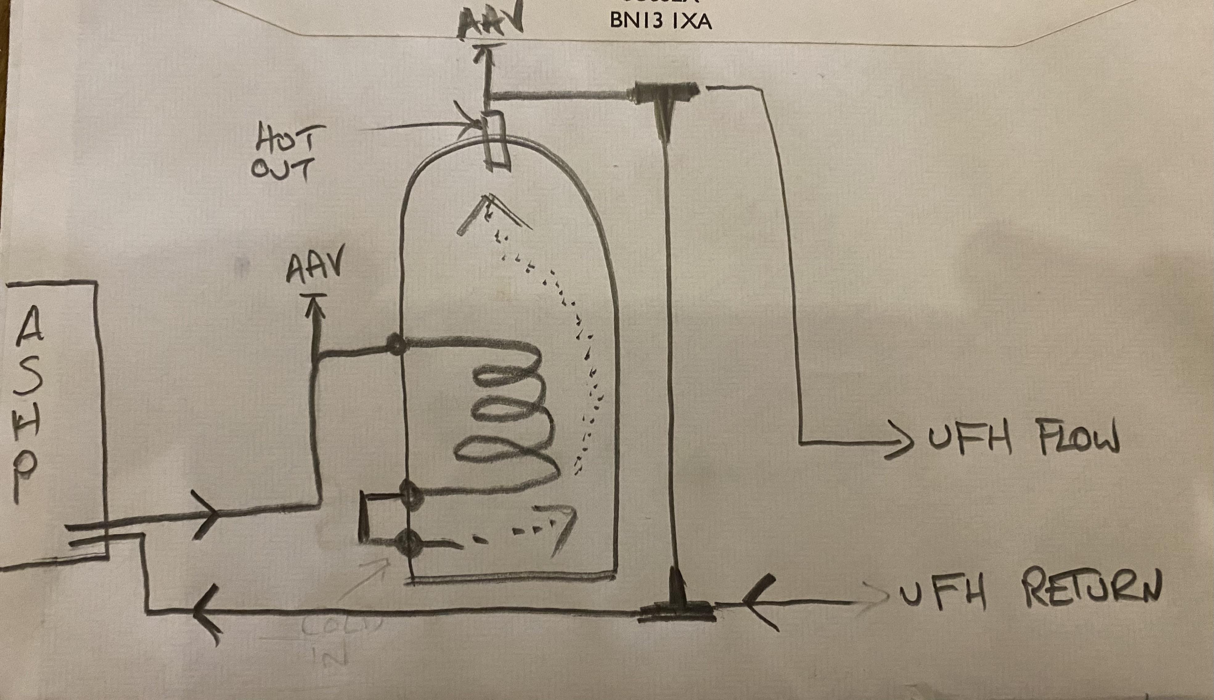
Hi. Yes, I re read this a couple of times before dipping my toe here. The transfer rate of heated water from the coil ( note : 5kw ASHP ) to the surrounding body of water in the vessel is insufficient in linear ( attempts to be linear ) output. Therefore we are advising here that the buffer ( a small UVC in this instance ) becomes part of the whole single system. In my pic there will be both hydraulic separation, initially, and then energy buffering second eg when the house comes up to temp.
-
If it’s a stainless coil then fine, but copper coils should never be left open to atmosphere as the insides get condensation and corrode badly over time, hence my seemingly unnecessary inclusion of it in my drawing. Fwiw, I would still include the coil in the pathway, even if it’s just teed in one side ( highest connection ) and capped off at the lower so it stays ‘wet’. The way it’s drawn by you @joe90 is an energy buffer arrangement, and will do as you suggest eg allow heat to the path of least resistance, so when hearing from ‘cold’ the lions share of heat energy will go almost directly to the UFH ( with any residual head diverting / bypassing through the buffer and back to the HP ). Only pitfall is heat has to creep all the way down the buffer to the very bottom to escape as return to the HP. Have the expansion vessel teed into the return down low so it’s on the coolest pipework possible ( or you get a wasteful heat bomb ).
-
Yup. One TV at a time will each receive undiluted signal.
-
What does your home cinema look like?
Nickfromwales replied to Adsibob's topic in Networks, AV, Security & Automation
In respect of Hollyoaks, no. The grizzlier the death the better. -
What does your home cinema look like?
Nickfromwales replied to Adsibob's topic in Networks, AV, Security & Automation
Dead man walking lol. But, yes. -
What does your home cinema look like?
Nickfromwales replied to Adsibob's topic in Networks, AV, Security & Automation
It would need to be vetted, to separate out victims who are watching such utter garbage but are not yet completely dependant on it, where then they would qualify for a longer term correctional program of rehabilitation. However, I must add a caveat; that if they also watch Hollyoaks then they go straight to for the aforementioned execution without any form of reconsideration. For those, there is absolutely zero hope. ”Nick for president!!!!” Moving swiftly on……. -
Deffo NOT motorised. The motorised Salus ones open in a few seconds these open slowly as the 230VAC goes into a heating element which melts a wax in a sack. That resultant energy turns into force which slowly pushes the pin hammer outwards to open the valve. Can you tell us what the flow temp is when the system is operating? The water temp getting to the 22mm pipes at the manifold please.
-
I would not do this. Conversely I am in regular contact with Trevor of Cylinders2go and he has had to petition Telford to start producing small buffer tanks ( sub 100L ) as there are lots of enquiries for these to be retrospectively installed in ASHP installs where they should have gone on on day 1. You already have it, it’s bought and paid for, so my advice would be to plumb it in as I show above and keep the ASHP as happy as possible. No 2 instances are really the same, so this is general advice, but I’ll put money on it that removing it would be a bad choice. Measuring its success as is is not a fair representation of how it ‘could’ perform, so as it’s there anyway, plumb it as above and see how you get on. Around £150 of antifreeze will need introducing to keep the concentration levels as required.
-
If you feed the ASHP into a coil there is bugger all primary volume, and a far reduced medium for transferring heat energy from one ‘side’ to the other. This is being demonstrated here. Buffers can he volumetric or energy devices, so can be plumbed in in 2 different ways to do 2 different things.
-
LAN C can go into a powered router / splitter and then feed C + a second LAN cable off it. The second cable can go down and behind the skirting and along through the wall to B. Coax at C can be split TBH, if you do not see both TV's using the coax at the same time routinely? If you can hide it at location A, a 5ghz AV sender could be used to get TV signal from A to B.
-
What does your home cinema look like?
Nickfromwales replied to Adsibob's topic in Networks, AV, Security & Automation
All of the soaps nowadays have sod their souls to the devil and "storylines" are in the gutter. People who watch and perpetuate them should be publicly executed without trial. -
Are TV aerials becoming obsolete?
Nickfromwales replied to dnb's topic in Networks, AV, Security & Automation
Maybe just a little swearing, but certainly politics do pop up..........rarely goes well. -
What does your home cinema look like?
Nickfromwales replied to Adsibob's topic in Networks, AV, Security & Automation
The real question is; how loud you can turn this up before pissing off the neighbours......? You can get some very big sound from some very small enclosures, but will you ever get to appreciate it is my issue. I've moved to a semi where I am mindful of the neighbour, and strategize when I give my now modest system some welly, but I could not ever dream of cranking my ol' faithful Yamaha DSP A2 up via my ( since sold ) Kef setup or there would have been murders. I used to run 2x Kef ref 104.2's, 2x Kef Q65's 2x Kef Q55's and a 95c with an active Velodyne subwoofer ( all bought second hand for sub £5k from someone who shed this stuff as soon as the latest replacement arrived at Quinns or A.E. ) and the SPL was just staggeringly good, if you like that sort of thing. I now have gone for audibility second and clarity first, ( with just a bit of subsonic ), achieved by a good ( large ) Samsung sound bar plus an accompanying matched subwoofer, with the sub being hidden away in the corner out of sight where it still rocks the room well enough. Not even close to a whiff of my what my old setup was capable of, but certainly a 'good enough' and compact / discreet enough setup to suit me ( and the neighbour ). I would definitely consider a much bigger and therefore 'visually obtrusive' system later down the line, if |I can ever get into a detached home that is. These days, my sound pollution is contained to my Sprinter, where it does not offend. 3x 12" subs sit directly behind my drivers seat and rattle my ribcage nicely. Kevin and Perry go extra large in there -
There should be a pump sending water to these 2 manifolds, sucking heated water through a remote TMV? ( @PeterW, the same as was at @newhome's when we got there, eg the red Reliance TMV's which governed the flow temps to the floors ). Agree it's likely to be weak / dying actuators, OR worst case the flow and return the wrong way around on that one problematic manifold causing the actuators to 'jump' whilst opening. @steve1986 these wax actuators start to open around 30-60 seconds after they get fed with 230v ( and the wax in the head slowly starts to get melted ) so the elapsed time, where you are hearing this issue, is relative to the actuators going from partially to nearly fully opened. This is deffo being caused by the actuator(s). If you wish to fault find before buying new actuators, simply swap the 4 there over to the other manifold, as a process of elimination, and see if the issue migrates or not.
-
@joe90 are you heating the 'buffer tank' via the coil, or are you using the coil to extract heat? The whole idea of a buffer is to add volume to the primary side so going via a coil will not achieve that. In honesty, I do remember sorting the deal out on price, but I'm pretty sure I did not spec the cylinder you bought to use as a buffer..... IIRC you followed @PeterW's install that he was on at the time where he used the same UVC as a buffer? Been a while of course. Agree that it's a simple fix to reconfigure, but with the caveat that the system volume will increase, thus, requiring an additional volume of antifreeze when you mix ( combine ) the 2 bodies of water. You have 2 filling loops atm? One for the ASHP primary and a second for the internal heating system? Internal UFH on inhibitor only and antifreeze in just the external primary's? Run the ASHP flow through to the buffer coil inlet, and come out of the coil output and feed that into the bottom ( cold in ). Then take the flow from the 'hot out' back to the ASHP as the buffer return. You then need a tee immediately off the top connection of the buffer ( the 'hot out' ) where you will pick up the flow to the manifold, and then a tee lower down the same pipe run to pick up a return for the manifold.
-
Looking for internal dimensions of Wago wiring center (L32 L60)
Nickfromwales replied to joth's topic in Electrics - Other
???