Jenki
-
Posts
832 -
Joined
-
Last visited
-
Days Won
7
Everything posted by Jenki
-

new wiring, all sockets tripping charging a phone !?
Jenki replied to connick159's topic in Consumer Units, RCDs, MCBOs
If you look at the empty boards the isolator is on the RH side, and the SWA incoming on the LH side, possibly moved the Isolator to make it easier and took the Neutral with them. I think just moving it can't make it any worse. and might be a quick fix. However the lack of understanding of this, would make me question the quality of the install I'm sure we've all made silly mistakes, and sometimes a little distance and time can be the light bulb moment needed. -
new wiring, all sockets tripping charging a phone !?
Jenki replied to connick159's topic in Consumer Units, RCDs, MCBOs
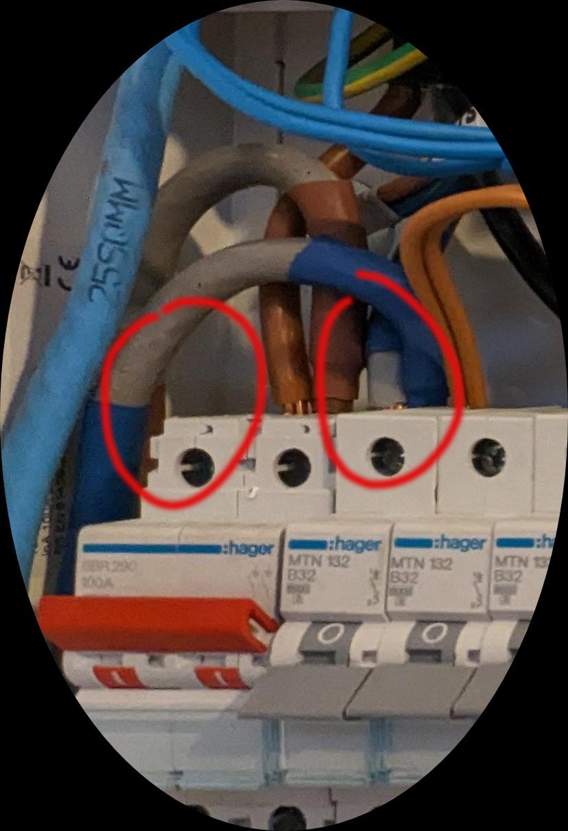
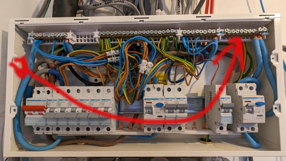
@connick159. The above image shows a blank unit. Forget the two bits on the RH side. On the RH side, follow the blue from the isolator up to the RH N bar. From there 2 N go to the 2 RCD's, from each RCD a blue cable goes to two separate N bars. Yours doesn't seem to do this. You have circuit cables ( on your CU you have N bar above the isolator with circuit cables.) These should be in the empty N bar further to the Right. It is essential that any brown cables connected to MCBs on an RCD, the corresponding Blue cables are connected the N bar of the same RCD. If not it will trip. Hopefully this helps. EDIT: I think, moving this cable from the left to the right might fix the problem. But use the first photo to make sure the logic is the same.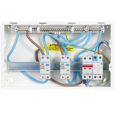
-
new wiring, all sockets tripping charging a phone !?
Jenki replied to connick159's topic in Consumer Units, RCDs, MCBOs
@Nickfromwales Ok. Fair enough. Neutral don't look correct. One out of isolator into neutral bar above isolator , then some circuit neutrals, and I assume a neutral tail supplying the RH N bar. This will cause the RCD to trip. Circuit cables should be correctly located in the right hand 2 Neutral bars. Not with the main isolator, these would be for non RCD circuits? -
new wiring, all sockets tripping charging a phone !?
Jenki replied to connick159's topic in Consumer Units, RCDs, MCBOs
Got me thinking. Looks like there is no neutral in the isolator, but in MCB? This will cause the tripping. Is the idea that the 32mm MCB is feeding the second CU? The Supply N needs to be in the isolator, then out of the isolator into the RCD's input.
-
new wiring, all sockets tripping charging a phone !?
Jenki replied to connick159's topic in Consumer Units, RCDs, MCBOs
@connick159, the replies here are not what you want to read, but you are where you are. We can try to help, ultimately it will take some testing of circuits and that can't be done remotely. So the only help I can offer, is advise that the person responsible for the rewire is out of their depth, and a plug in tester cannot produce the test results you need to find the fault / s. To assist with the awkward discussion about competency My initial thoughts are( and not exhaustive) 1, Why are the cables not glanded when entering the CU's 2, the layout of CU 1 is confusing, i.e LH side isolator, then the RCD's are running RH to LH. 3, all 32A mcbs are on the LH side, regs mandate splitting circuits to minimise nuisance tripping i.e. up sockets and downstairs lights on one RCD and the opposite on other RCD etc 4, CU 2 has no RCD protection to circuits, ( but looks a bit neater) 5 Why choose plastic dual RCD CU and not metal RCBO protected as per 18th edition of BS7671. Good luck and I feel for you. -
new wiring, all sockets tripping charging a phone !?
Jenki replied to connick159's topic in Consumer Units, RCDs, MCBOs
This is a rewire🧐🙈. My OCD can't cope with the wires entering the CU, never mind inside. @connick159 are you sure he's an electrician😞. Did you see him using a larger tester before powering up circuits.? To help us help you can you ask him for his test results ? We might be able to see the problem, (answer will be he hasn't done it yet or doesn't do it..) The dead tests @ProDave mentioned earlier would identify crossed circuits, and or N-E faults. If your electricians fault finding is maxed out at plugging in a socket tester then he's going to struggle. -
Prompted by a side track in this thread. Has anyone who's built an energy efficient / Passive house installed a large tropical fish tank _400L +? With the water sat in the tank at around 26 deg, how does this affect the house? Loved having a large tank in the last house and the above thread made me think It might be a good idea to add a warm fill and waste to a suitable tank location for the future, then the rabbit hole opened up and I started thinking about the effect on the house heat?
-
+1 minimise all joints that's the whole purpose of the manifold.
-
@Super_Paulie I used a TMV, and although the spec doesn't say you can get below 30 deg, I managed to get 26deg accurately. it was a god send. if I was planning again, I would also plumb in a suitable waste for the water changes. (I used a pump and hose for a 500L tank) ADDED INFO. If you add a TMV you can put this next to the manifold and run only 1 feed?
-
ICF How much more expensive ?
Jenki replied to Dave Jones's topic in Insulated Concrete Formwork (ICF)
It's only a low risk area so only require barrier, but rebar connections from footing to bedrock and footing to ICF mean I'll have to seal the barrier and rebar🙈 I'm sure when the final spec comes back from the certifier there will be rebar in the rock, I'm unsure how they think around 45T of concrete can be blown of its foundation of rock but that's what they said, the detailing of the radon becomes more and more difficult 😔 -
Depending on the pipe used, you maybe surprised. I'd trail fit the rad and see if the pipe bends easily enough. The least joints the better. IMO a 90 bend may give you more problems . Also try using the left pipe for the right-hand side and visa versa.
-
ICF How much more expensive ?
Jenki replied to Dave Jones's topic in Insulated Concrete Formwork (ICF)
I'm sure when the final spec comes back from the certifier there will be rebar in the rock, I'm unsure how they think around 45T of concrete can be blown of its foundation of rock but that's what they said, the detailing of the radon becomes more and more difficult 😔 -
ICF How much more expensive ?
Jenki replied to Dave Jones's topic in Insulated Concrete Formwork (ICF)
Just a quick update on my build, and the rebar, which initially was at over 3KM. After chatting with Will at Poly steel, and the guy preparing the drawing for the certificate of design, there seemed to be large turning forces added to the walls, so the foundations (bedded on rock), were going to be huge to resist these forces. The discussions resulted in the ICF walls being designed to stand on tier own ,not taking into account the Roof structure? once the roof (fink trusses - and counter battens) were added these turning forces (Moments) were eliminated, and the result will be a more standard strip footing and a reduction of rebar by 50%. A lesson that even though the cost of the ICF calculation were part of the ICF purchase, the disconnect between the two engineers could have cost considerable £££. -
Foam Gun Cleaner - am I doing something dumb??
Jenki replied to jayc89's topic in General Self Build & DIY Discussion
And proof a little knowledge is dangerous 🤣. I only drink decaf and still here. -
Foam Gun Cleaner - am I doing something dumb??
Jenki replied to jayc89's topic in General Self Build & DIY Discussion
"How harmful is dichloromethane? The substance is irritating to the eyes, skin and respiratory tract. If swallowed the substance may cause vomiting and could result in aspiration pneumonitis. The substance may cause effects on the central nervous system, blood, liver, heart and lungs. Exposure could cause carbon monoxide poisoning." Thanks for the tip @SteamyTea, but the above has put me off..🧐 I'll just buy a new gun when it's fecked rather than me being fecked🤣 -
10mm polycarbonate, I used 6M long polycrub use 7M Bends no problem the pain is connecting the joint strips
-
Wylex Combined AFDD/RCD/MCB
Jenki replied to Onoff's topic in Regulations, Training & Qualifications
@MikeSharp01 , just got this in my inbox Fusebox AFDD. -
Is the porch insulated, are the wall connecting the porch to the house well insulated or are these deemed internal. Answer the above as @joth asked and you will have your answer. As an aside, you mention air tightness is a bit OTT, if you use the heat loss calculator, and play with the ACH figures you soon see the benefits in running costs. And these are yearly savings.
-
ICF How much more expensive ?
Jenki replied to Dave Jones's topic in Insulated Concrete Formwork (ICF)
It's calm now (5mph)😁, but we regularly see sustained winds of 20mph gusting 30. -
If it's multiple joints solvent weld would give a more rigid solution, but both will work, just support the joints and ensure the pipe cuts are clean, square and free from burrs to minimise the chance of flushed waste catching in the gaps. And make sure the fall is correct.
-
ICF How much more expensive ?
Jenki replied to Dave Jones's topic in Insulated Concrete Formwork (ICF)
Foundation course will be poured first, then I'll make a decision if I want to put all 4 course up before next pour. PolySteel have metal ribs t&g and clips that secure blocks to each other. So it's possible to use timber to screw the blocks to each other. You can use this timber for propping as well. I intend to build my scaffold on the inside and use this to assist with bracing. -
ICF How much more expensive ?
Jenki replied to Dave Jones's topic in Insulated Concrete Formwork (ICF)
😬🙈. Me too. All insulation for that matter. -
Cut it back, I tend to use a liquid thread seal, don't trust the PTFE, as you can not see the joint, ideally the female boss will be flush or just below the tile.👍
-
It's hard to tell, but if there is space under the joists for the pipe I can't see why you can't get the pipe in there? Flexi is a bad idea. You will regret it. If it can't be done with solid pipe you need to re-design IMO.
-
I've cut a lot of the these down in the past, does it seal on a fibre washer of PTFE/ pipe seal? If the former, I've found once cut use a piece of 180 grit wet and dry on a flat surface to get a good sealing surface.