Alan Ambrose
-
Posts
3261 -
Joined
-
Last visited
-
Days Won
15
Everything posted by Alan Ambrose
-
Sharing Fee Proposal with other Architect
Alan Ambrose replied to flanagaj's topic in Surveyors & Architects
I think it is a little unprofessional to share the whole proposal without explicit permission. You could briefly describe the scope so the other architect can check you’re not mistakenly comparing apples & oranges. I accidentally copied a proposal from one SI specialist to another when emailing an SE. I was really embarrassed and apologised to both. -
I feel a little more cautious than some here. If the land isn’t actually residential curtilage then using it for garden-ish activities and workshop sounds not so legal. If you’ve been doing that for 7 years without challenge you may be able to claim it’s now residential. But, if not, you might not want to alert the LPA.
-
Planning Appeals - Statement of Case Examples
Alan Ambrose replied to phykell's topic in Planning Permission
Yeah, I think it’s a matter of taste whether you hand over the whole thing to ‘trusted professionals’ or diy a bit. I generally do the latter, but sometimes that’s probably not the right course. Be aware that appeals seem to be taking forever right now. I’m not sure whether ldcs are householder or ‘other’, but I think other are the slowest - probably over a year. One strategy might be to run the appeal but put in a slightly changed application but this time badger the LPA into saying what they *will* allow. Or maybe a pre-app and push hard for a meeting. You might get a bit more traction once they figure you’re not just going away. -
Planning Appeals - Statement of Case Examples
Alan Ambrose replied to phykell's topic in Planning Permission
You’ll find examples i.e. actual cases (probably) on your LPA’s portal (there are on mine). Both appellant’s and LPA’s cases. May take a while to find similar circumstances to yours as (at least my) LPAs search facilities aren’t the greatest. Not sure why you’ll want to write one though if you’re using a planning consultant - as that’ll be their main skill. -
>>> what Wattage p/m2 to go for? Well you could just guess (I did and played it safe at 200W/m^2) - by and large it only affects the warm-up time - the thing will switch on and off to maintain the set-point temp - less switching off and more switching on for a lower wattage mat. If your bathroom is, say, 5m^2 you'll have a 1kW heating source which sounds ample. You could do a quick calc using ubakhus or similar to get the U-value above and below and the likely set-point (28C?), min below floor temperature and min air temperature above. One tip I've seen and used is to either put the themistor in a tube so it can easily be replaced or bury a spare thermistor which can be used later if the first one fails. I've done the latter before - although I can't imagine the failure rate is very high.
-
What is allowed to be left on a building site?
Alan Ambrose replied to Vijay's topic in General Self Build & DIY Discussion
Assume your site has heras or similar around it? Add screening fabric? Sounds like the neighbours just don't like the look of it. You could ask them directly - a little transparency goes a long way. And then offer to put up some screening fabric. I believe enforcement has to react to anyone's complaints even if they think they're nonsense. Also, enforcement appeals are crazy slow, so you can probably spin this out for 3 years if you want. I once had enforcement ask for drawings after a neighbour complained about the height / bulk of a PD cart lodge. Supplied drawings. (Actually I did need to draw them at that time as the building was so simple it didn't need real drawings.) End of. I've an antsy neighbour atm who is worried about drainage. He also complained (to me, not to the LPA) about having windows in the side of our single storey design. He has a 3m high x 1m wide hedge between us FFS. Take your time, try and stay calm and respond rationally. Re the drainage, I sent him our topo and some references to SuDS and asked him if he had any calcs, drawings, images etc. He didn't reply, so I assume he hasn't. I suggested that with some good science and engineering we would handle whatever potential problems we faced. -
Maybe I can ressurect this thread... Anyone have rough costs per ton for budgeting rebar in 2024? This is 12.2T, all simple bar, no mesh, 10 forms, 3 of those just off the shelf bar, H10 to H16.
-
@Pocster oh hail ye deity moderator
-
How to decide how big to build?
Alan Ambrose replied to Ed_'s topic in New House & Self Build Design
>>> the insulation can be left until later Suggest not - you need a waterproof, insulated concrete box. You don't have to fit it out, but you may want to put a plant room, utility, storage etc in there which will mean some minimal fitting out e.g. electricity, light etc. Basements are usually expensive, but if your ground demands deep foundations or is very sloping it may not be a lot more expensive than not having one. -
>>> vondidwred Is that special SE language? 😃
-
From an EE perspective: How long before house installs need a proper circuit diagram and cable labelling like industrial set-ups do? It's a bit nonsense have to guess/figure out what cable end corresponds to what other cable end and draw the circuit out on a scrap of paper/in your head. The situation is quickly getting more and more complex with PV, diverters, batteries, Loxone, wifi controls, car chargers, 'high integrity' backup circuits/CUs, earth relays etc etc - the chances of having the correct picture in your head just by observation are getting less and less. While EEs and industrial sparks sometimes have to debug an undocumented PCB or control cabinet, it's quite the exception.
-
>>> The decorators knocked off everything with lights in the name. They're papering two of the ceilings and wanted to remove the light fittings. It's v easy to trip RCD/RCBOs by shorting N to E when L is swtched off. I would wait until the lights are wired back in properly before spending much time on it. Anyway, it's not rocket surgery - as an EE you should be able to figure it out.
-
>>> I'm an electronics engineer, though not an electrician. I'm safe to disconnect things and reconnect them. So what's a good procedure to track down where the fault is? OK you'll easiy understand this then. An easy way is literally to measure the residual current 😃 in each circuit. Often things like LEDs bulbs & controllers actually have a few mA of leakage current. If those, along with anything else on that circuit, add up to the trip level (or thereabouts) then ... the RCD trips. There's a bit of subtlety about type of leakage and type of RCD (e.g. DC leakage vs. AC leakage) but it's normally fairly simple. So, if you have something (preferably non-contact) that will measure, say, 0-20mA then it's all quite straightforward. Actual electricians might purchase a special device for that measurement if this is something they come across often. Suspect anything which is a more modern non-linear load - LED drivers, induction hobs, anything with a VFD in it, heap pumps, inverters etc. bigclive on youtube, I think, has some teardowns of RCDs - they're actually quite clever bits of electromechanical engineering.
-
How Often Does Your Building Inspector Visit?
Alan Ambrose replied to Triassic's topic in Building Regulations
>>> Should I worry that my inspector is showing little interest in my build? There have been a couple of reports on here that the BC has effectively changed their mind. e.g. in the closing stages of a build figured out that a sprinkler system should have been put in. They don't have any liability for their work, so if they screw up, that's your problem. So, it's helpful I think if you can keep them engaged on site and try to ensure that if there's anything they should be looking at they actually are looking at it. -
Keeping a passive house cool
Alan Ambrose replied to Russdl's topic in Energy Efficient & Sustainable Design Concepts
Huh. neat, thanks. -
Keeping a passive house cool
Alan Ambrose replied to Russdl's topic in Energy Efficient & Sustainable Design Concepts
@mike2016 That's interesting - how wide are your brise soleil? When you say '4 internal cassettes', are those the ceiling mounted ones, kind of like these below? BTW feedback from things that have worked well for people who have finished their builds is invaluable for people like me that are still in the pre-build stage. -
Keeping a passive house cool
Alan Ambrose replied to Russdl's topic in Energy Efficient & Sustainable Design Concepts
@Russdl Did you use any other forms of solar gain mitigation e.g. low-g glass, or only external blinds? Also, did you see any verified shading numbers from Phantom Screens or did you take them at their word? BTW thanks for your post - in my pre-build calcs with PHPP, I've come to the theoretical conclusion that I can focus only on lowish-g glass (64% transmittance, 35% solar gain) and external blinds to bring down the overheating risk substantially.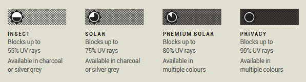
-
Keeping a passive house cool
Alan Ambrose replied to Russdl's topic in Energy Efficient & Sustainable Design Concepts
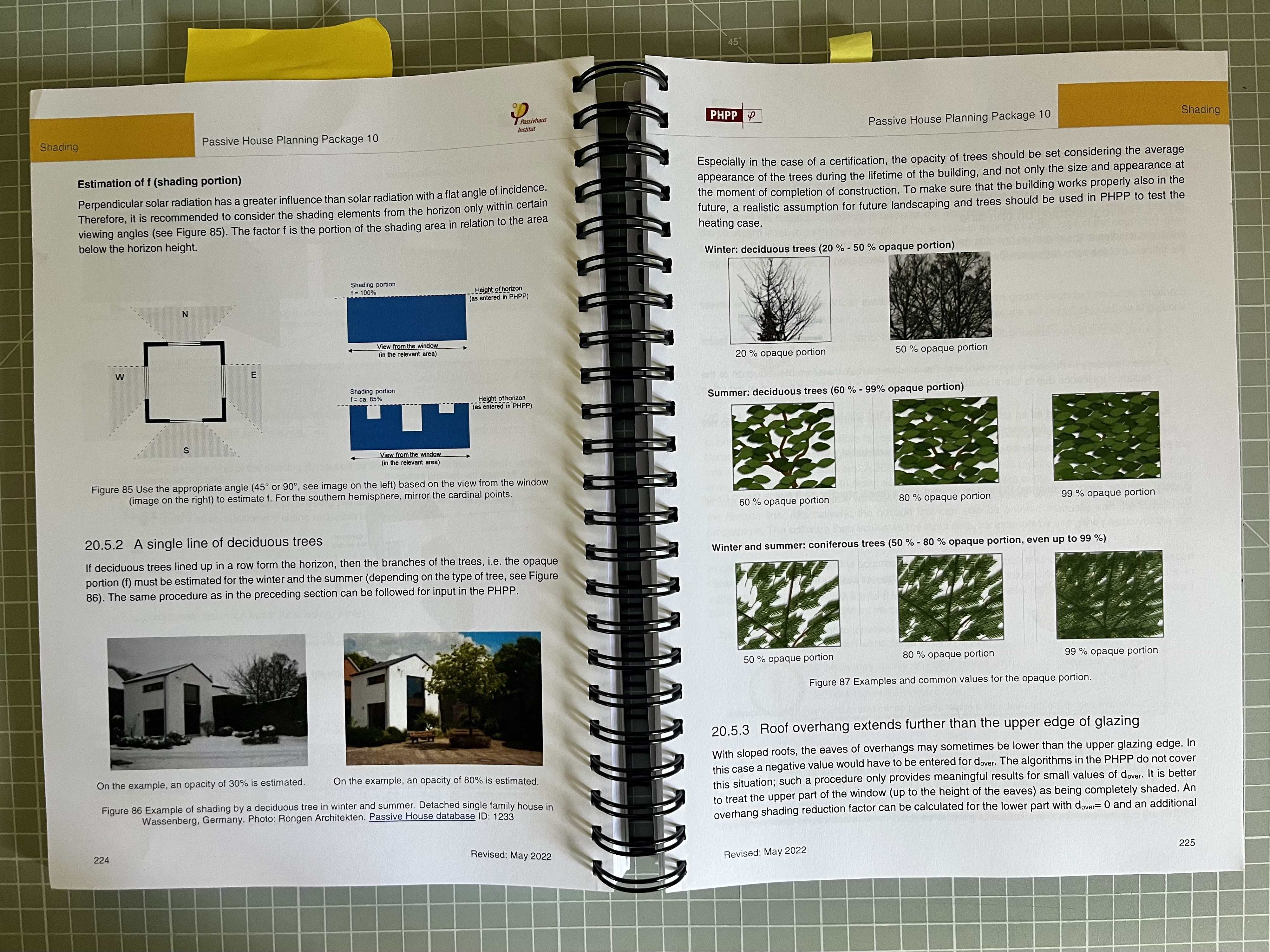
FYI: Part O - "Foliage from shrubs or trees is not a valid method of shading for calculation." An unfortunate choice by the algorithm designers, as that's by far the greenest solution. PHPP has a busy system of shading calcs that includes window reveals, adjacent buildings, eave overhangs, brise soleil, external blinds, low-g glazing etc. It also allows external software calcs. It has a section for trees but nothing for shrubs as far as I can see. TM59 (I don't have direct experience yet) seems to have a similar feature set to PHPP. The relevant PHPP page below: FYI: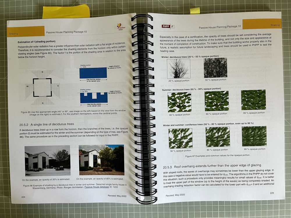
-
Something like: Prop up with acrows checking levels. Remove metal shims. 'Shutter' fairly convincingly as the grout is very liquid. Pour - I'm thinking just up to a level a little higher that the bottom of the RSJ. So the RSj is supported without any air bubbles but, to allow thermal expansion of steel, not too enclosed . (Others may have different views.) Check the levels again straight after pouring 😃. When green, remove and trim any flashing etc. Cover with polythene in hot weather? Takes ~1 month to cure to max strength, so resist the desire to load up quickly.
-
Keeping a passive house cool
Alan Ambrose replied to Russdl's topic in Energy Efficient & Sustainable Design Concepts
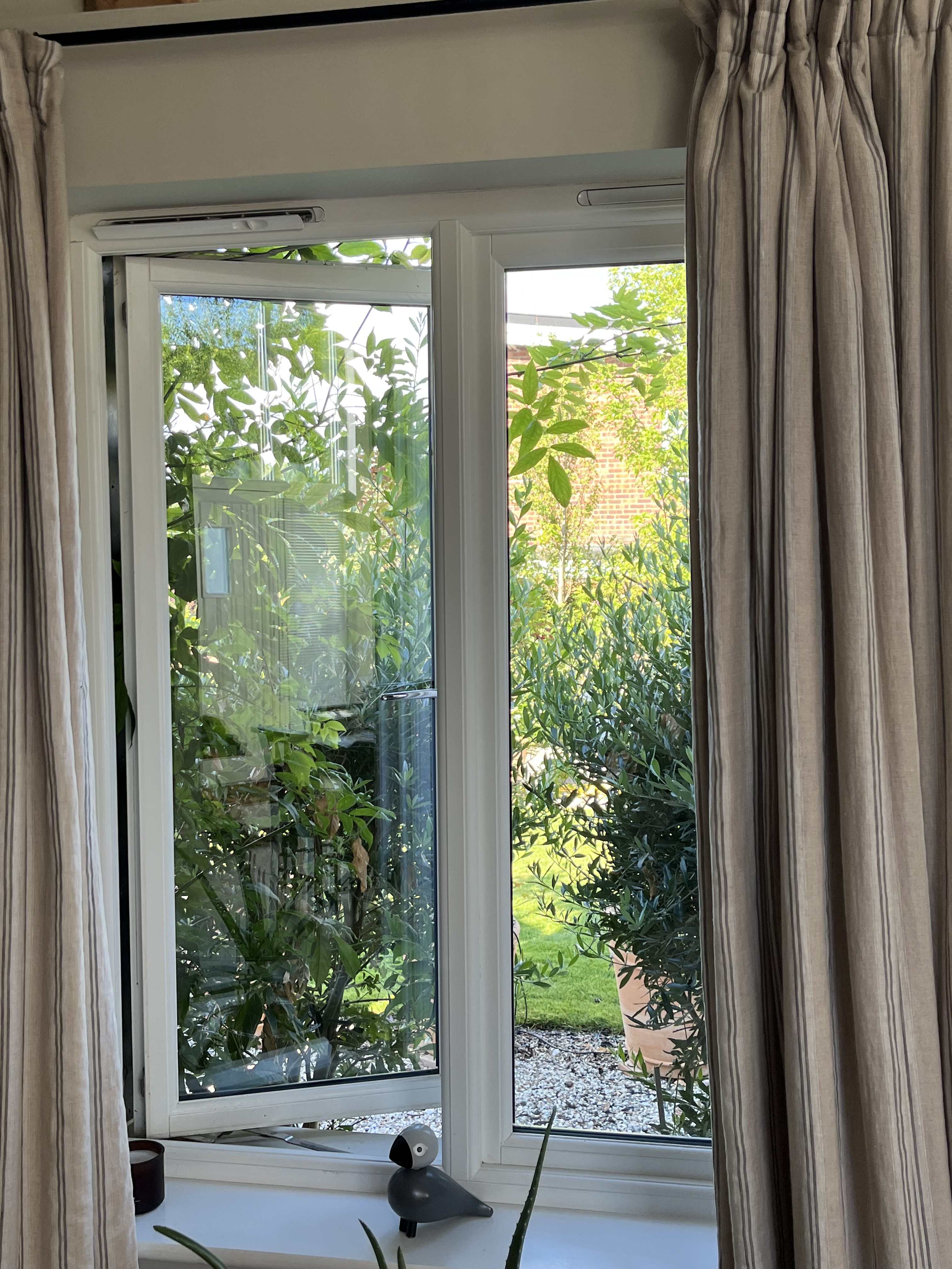
>>> Our secret weapon is a row of trees on the south of the plot Yes, in our existing single storey, we let the olive trees and other shrubs outside the windows grow in the summer and they make for a lovely view out of the window … and they love the sun. In the autumn, I give them a good short back and sides and we get a bit of solar gain for the winter. Very effective. This mitigation is not acknowledged in simple part O - I’m not sure for TM59 and PHPP.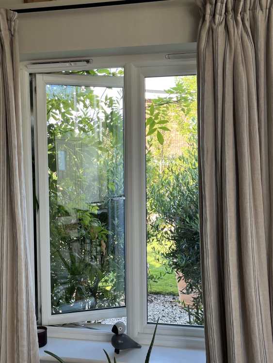
-
OK a lot of those glass balconys don’t have the balustrade and some linear ones obviously not the returns and fixings to the walls. The setup you have makes life a lot simpler. Still all down to the BC and SE. I think it’s posssible they might just wave it through.
-
Hopefully that was just temporary shimming.
-
Cat6a cable everywhere, um, now what?
Alan Ambrose replied to Tom's topic in Networks, AV, Security & Automation
Lots of the countryside doesn’t have 5G or sometimes any mobile signal at all (Cornwall, last time I was there). -
That’s impressive. Know how much is ‘baseload’ i.e. fridge etc? What kind of heating, sorry I forget. Also, per m^2, so we can compare?
-
Does your new glass have a bannister or similar above? If not, it’ll be the torque around the fixings at the bottom that is the problem. As others have said, your BC will almost certainly require SE sign-off. The weight of the glass itself probably isn’t the problem.