


Gus Potter
-
Posts
2339 -
Joined
-
Last visited
-
Days Won
29
Everything posted by Gus Potter
-
Thanks for the heads up Devil. Will aim to be a bit more OT and concise when posting. I you are a self builder you may be placing some reliance on the fact that a BC company is carrying out site "checks". The CDM regulations relate in part to safety during construction and also after completion. If the site checks are no longer taking place then the BC company should advise on what action, if any, is required. Triassic. This could be the reason for asking for a progress report. It may be that they want to limit the site visits to those that are safety critical and rely on photographs for the items that are less risky.
-
No, this should not happen. Having dealt with the system down south and private BC, experienced some real safety howlers etc. It seems like a race to the bottom. They did away with the clerk of works role years ago. It's only a matter of time before there is a serious accident and folk get killed. The thing is folks (Triassic excluded as asking the question) that these checks, controls and balances are for your safety! Undermine them to save a few quid.. why? Just to concentrate your minds a bit on BH. The CDM statutory regulations include self builders, look them up, you don't have to do too much but if someone gets hurt or worse you could find yourself in the firing line. Yes, it's not a hot topic on BH.. but the consequences can be a lot worse than a bit of condensation or worrying about a bit of cold bridging! Thank you Triassic for you post. Rant over for now!
-
Thinner and better alternative to 150mm PIR in cold roof insulation
Gus Potter replied to Adsibob's topic in Heat Insulation
Just a thought. I wonder what the structural issues are. I would start here. Often with an extension you need to get the pitch so you can get the tiles to work at low angle and if two storey get the flashings / cavity trays to function. One way of making a roof thinner is to close up the spacing of the rafters, however you have more wood that is more conductive than say PIR insulation, law of return and so on. I did a dormer attic conversion where I used cold formed steel rafters and stuck a warm roof on top, managed to squeeeezzzzze it in by about 10mm so it did not stick above the main ridgeline of the house. There are standard sizes available and brackets too so it may be worth a look if you are tight for space. A cold formed steel rafter is just like what you see on a B & Q roof but can carry more load than a timber rafter of similar depth I'll leave out the width for now. You can stick a rubber say EPDM membrane on a shallow pitched roof. -
Overthinking flat roof joists/wall junction preserving airtightness
Gus Potter replied to Olf's topic in Flat Roofs
You may be as the cost of maintaining the structural intergity, robustness and tying it all in may far exceed the cost of just adding in a bit of insulation else where. Ledgers can be fine but best to have some compression in the masonry as you need the weight above to top the masonry from rotating etc.. Hangers are not so good at taking horizontal loads, especially if they are retrofitted. When you take away a wall you need to remember that even if it does not appear to be holding something up it may be providing lateral stability to another wall that is, and that wall may be subject to horizontal wind load. That is your starting point. -
This requires a bit of lateral thinking. If you are a builder and you get the structural slab too high then you are in trouble. All other things being equal then it's a bit of risk management. Or they may have cast the structural slab too thin hence the 90mm... to fudge it up..
-
Structural Engineer Not Providing Connection Detail
Gus Potter replied to SteveMack's topic in General Structural Issues
Good points from George showing how you can make a small change that could have a big impact on the cost and buildability. George also mentions the debate about how a steel frame interacts with an existing (assume masonry walls for simplicity) structure. I'll have a stab at this.. to all, please feel free to comment. If you go back a bit, before the days of reasonably priced bifolds etc you often added a modest set of French Doors that maybe were a bit wider than say an existing window. Here, you still had plenty masonry each side to keep the building stable horizontally when the wind blew. Often you could just put in a concrete lintel or a modest steel beam just to hold up say; the wall on a second storey, floor, roof above.. you only had to deal with the vertical loads. But now we are putting in much larger openings and are left with much less brickwork to stop the building from moving from side to side. When you do this you can end up with masonry each side of a large opening that looks more like a column than a wall. One problem that starts to crop up is that a column is much easier to overturn (push over) than a longer length of wall. Also, you have a shorter length of mortar bed to resist the sideways (shear) forces and a few other bits and pieces. @George "I have tended to use the existing building where possible..." The key bit in Georges good comment for me is "..where possible." If the remaining walls won't do the job then often the SE is faced with a dilemma. Can you (SE) say.. well the remaining walls will take a bit of the sideways load and I''ll introduce a steel portal / box frame to take the rest and keep the steel sizes etc down or do I assume that the remaining walls don't make any contribution and design the steel frame to take all the load. Theoretically you can assume the former but a brick wall (and what is attaches to) behaves in a different way from the steel. Steel is more elastic than brick and it (steel) does not suddenly crack. An easy way of explaining this is to imagine that you connect together a plank of wood and the same size plank of steel with the strongest and stiffest glue you can imagine. Put your composite plank over a river and walk over it. (how you do that I don't know ) Both the steel and the wood will bend by the same amount as they are connected together. But steel is less elastic (stiffer) than the wood (called the modulus of elasticity, Youngs Modulus) so the steel will take more of the load than the wood as the wood is more "stretchy". This principle underpins the design of a flitch beam... it's very clever really but simple when you think about it. Suddenly the analysis becomes very complex and thus expensive design wise and even then the structural modelling of this is still only a model. Most SE's for practical purposes on small domestic applications (where the remaining walls are not enough) will design the steel to take all the vertical and sideways loads and limit the amount it moves by, so they don't crack the masonry excessively. This may seem like the SE's are being lazy.. but many know that while you could undertake a more refined analysis you will get tripped up when it comes to designing the connection between the steel and the masonry.. so back to square one. There is also the issue about how confident you are as to whether the builder will actually do what they are supposed to do. For small domestic stuff where supervision may be not as robust the simpler you make it the better, not just in terms of cost but also in terms of safety. To get the best value for this type of work you maybe want look at this in the round. Do you for example need to live in the house while work is going on, how hard / complex will it be to prop and so on. Will the size of the steel connections start to interfere with your window / thermal details ect. How much of a ceiling height can you live with vs downstand of a beam. I often find that the cost of the actual steel is not the main issue, it is the labour and complexity of the fixing of the steel to the existing building and the cost / labour involved in the temporary works. Sometimes you can skin the cat in another way where it's more economic to take the wall down above , take the load of the propping, put your steel in and rebuild the wall after... any takers? -
A few words of encouragement. We have been designing rafts for many years (decades). The method is tried and tested, proven to work. Now we want to have rafts / basements with insulation (ICF) underneath.. the insulation is essentially just treated as another layer of soil... The structural engineering principles are the same, the harder part is the detail so you can avoid thermal bridging and so on, stop the building lifting up when the wind blows say. An old building may well have shallow founds and move about up and down between the seasons as the ground shrinks and swells. A ICF raft founded at the same depth as the original founds is more likely to move up and down at the same rate as the original house. It's common sense.. but you may need to spend a bit of money exposing the existing founds etc so the SE can justify the design. Find an SE that understands these principles and you are up and running.
-
Planning permission for building within RPA of protected trees
Gus Potter replied to Raine's topic in Planning Permission
Ta Raine for the heads up on what an Op is. Raine.. if you put in a bit of work here as it seems you are doing and start to make some contacts you could easily find yourself in a good spot, have money left over.. which will get spent on tv's, a nice hob, crapets, blinds, maybe some new pans if induction hob..etc. All the best with the project. -
Planning permission for building within RPA of protected trees
Gus Potter replied to Raine's topic in Planning Permission
@DevilDamo Give me ten min while I figure out what an OP is, or can you or anyone help? Is an OP the same as on topic.. OT? Devil.. Do the planners fancy their chances faced with an evidenced based Arboriculturalists report covering say the health of the fauna backed up with an evidenced based foundation proposal from an SE in support. It's a bit like contractors getting into a spat when they don't actually have a leg to stand on. As a past contractor myself I have heard that this goes on (caveated etc for the faint of heart) So to answer the question... you have got to be a brave Planning Officer to refuse.. as if they do they could get full pelters while also being asked what the technical grounds for refusal are ..and the clock for them is ticking. For all BH members.. if you are willing to spend the time understanding the technical stuff and can present a recognised technical / evidenced based argument then the council have to consider this. "can the council still refuse to grant planning on the basis of the construction being within the RPA of the TPO?" @DevilDamoMy view is no, but the conditions attached may be so onerous that it is not practical to construct. -
Planning permission for building within RPA of protected trees
Gus Potter replied to Raine's topic in Planning Permission
Hello Raine. I'm new to forums such as this. Have read around ebuild but was their demise due to the fact that they went commercial? You can sometimes make life easy here. Get your SE in early..if your serious then at some point you'll need the SE to design founds etc anyway. Get them working with Arboriculturalists. You'll probably find that with the right choice of folk they get on well. When you couple up the two you can end up with a pretty evidence based argument. In this case the " qualifications" are backed up with calculations and double PI cover? I worked on the SE design for the Tottenham Hotspur ground training ground gym a while back. Lots of TPO's .. RPA's (for all... to save you looking it up.. tree protection order, root protection area.. so you don't compact the soil round the roots and thus kill the tree anyway) the job was a joy as during the works we found the long jump pit that was used in the filming of Chariots of Fire. I spent a good while on gathering info for the desk top study, new about the film and so on (you get to spend time as an SE studying history and old interesting photos) , SI info etc. The planners / council were helpful to say the least.. good for the CPD and CV all round. Interestingly there were objections.. as not everyone supported spurs, and some folk just were just not that keen on footballers..and the "type they attacted" I can tell you that the deflection limits were reduced to accomodate the large mirrors on the walls. Part of the brief was that in order to train effectively you need to be able to see all of your body? In summary sometimes what initially seems to be a problem can be sorted with a different (people) approach.. don't always assume that the council / planners etc are going to be hostile from the outset. Often you get a communication that appears to be "official" ,and "hostile".. some folk are not that good at communicating and don't really mean to rub you up... after all you could be their Mum and Dad! Start off with the light touch, keep the big stick out of sight, hopefully you don't need to use it.. -
Good points Peter et al. You may wonder how he works this out! If you search the net for "guide to good lead work" then you will find extra advise and tips on what to do (laps etc) and what not. Make sure you read about patination oil as you don't want a nasty big lead oxcide (white) stain down the roof after you have done all the hard bit.
-
I'm a relative new comer to BH, but it seems that there are "no friends in the desert" on BH.. Rommel WW2.. maybe a take/adaptation on the French Legionnaires established circa 1831? Onoff still has time to finish the bathroom and the gate before BH birthday... last laugh and all that.
-
SAP fail mainly due to walls
Gus Potter replied to WWilts's topic in Environmental Materials & Construction Methods
Thanks Peter.. I think you have forgotten more than I know, as have many members on BH. -
Great "old school" stuff from Onoff. It's amazing what you can do with a table saw with a bit of care, often no need to spend a fortune on tools you may only use once. @ProDave.. but the job is not finished.. I'm confident that Onoff will (eventually) find the correct imperial slotted screw to fit the countersink in the hinge, installed so that the slot is vertical so that externally the water won't lie in the slot (or for an internal door prevent paint drips) .. don't take my word for it, wait until you see the finshed result..
-
SAP fail mainly due to walls
Gus Potter replied to WWilts's topic in Environmental Materials & Construction Methods
Hello WWilts. Sorry if I laid it on a bit thick there. You could look at timber frame. Design is an iterative process.. (I paraphrase - there are a number of better qualified members than I on BH) you start by listening to a Client's requirements, understand how they want to live now and in the future. A good designer will do a bit of "gaming".. what if you have more kids, what if you need to change jobs and want work from home etc, what are your aspirations.. energy use.. ( to use a cliche). Now as a designer you have an incling as to what the "soft" requirements are. To make this work within a budget it starts under the ground. It may seem a bit odd but if you go for the simple stupid option this can really knock a lot off the builder's price as the tender field is more open for example. I often think and see that folk have spent a lot of money on structure (and associated foundations / labour cost) creating a daft open span, or just the wrong span. Get the basics nailed early then you can then use this saving to upgrade insulation etc and also spend some money on.. heating controls/ rainfall showers and so on, some Farrow and Ball paint, stuff which you get to have fun playing with and can see every day. Remember that a house is not just to keep the weather out and you warm.. there is value in being able to play with it , adjust stuff up and down. Visitors only see the finished result.. not the insulation. There is no harm in showing what you have achieved. Wilts it may take a bit of work but go back and review from the foundations up and you may get a pleasant surprise. -
SAP fail mainly due to walls
Gus Potter replied to WWilts's topic in Environmental Materials & Construction Methods
Consider the simple stupid. Roughly, as a ball park the labour cost on a new build is about a third for standard stuff, on a small extension this can easily touch 50%. (see R_Sole etc for good info) Some BH members are "in the trade" and can get a good discount and avoid the uplift due to complexity. But if you are starting out then maybe you want to make it easy to build. More local builders will be interested in pricing if it looks simple and they feel they can make a profit with less risk. The less risk they perceive the lower your price will often be. See what prices you get back with simple construction (avoid thin joints) then compare this with making it more complex.. remember that often you are working on a small scale unless you are a very wealthy Client. It's hard to do but you need to look at this in the round.. all the folk on your team should be pulling together. One big problem is that you often can't get a builder to price realistically without a descent spec.. it's catch 22. But starting with a simple spec can be attractive for a builder.. and once they are interested you can explore the cost of upping the spec. Good experienced designers will cost more but you get what you pay for and the really good ones will invest in you and give more than they take.. provided you pay their bill on time. To get the higher strength in a block you need more conductive material (density), less air.. air can't transmit load in this context. The thin joints offset this but you reduce your options regarding the builders who want to take the job on as they have to be much more accurate and this take time = extra cost. For me I would start with basic construction.. see how much that costs. Then you can start adding on the extra bells and whistles that appeal to you, energy saving etc, fire risk and so on. @Jason L"sorry, I'm just high jacking the tread for my house, i have a design SAP rating of A 93, with MVHR and i will try and make it super air tight, do you think I'm not going to need any heating on the first floor and in the attic bedroom, just towel rails in the shower rooms" Jason , it may be worthwhile having a chat with your designer about how the building is prevented from moving from left to right say (on the drawings) when the wind blows. You don't have too much on the ground floor to achieve structural stability by the looks of things. It may be a good idea to make sure you have a good handle on how the structure will work, then you can plan the services. If you don't do it this way then the saving on energy performance you think you make make may not be realised as you could end up with beams etc in the way of your ducts... sounds painful -
Onoff. Have you been playing with a biscuit jointer? Can almost see a wee scuff with the plane along the top on the end grain too! Built to last that gate. Oh, and is that a proper brass hinge at the bottom?
-
Basement waterproof concrete (Type B)
Gus Potter replied to Moonshine's topic in Waterproofing & Sealants
Is this an elephant in the room for basements with a high water table? If you stop for lunch, or the concrete wagon is delayed on a hot day and you have some interruption in the pour where you have say no water bar what are the solutions? or do you just hope for the best even though you suspect that your waterproof concrete has a potential weak spot in it.. loss of aggregate interlock? A point?.. you have "insurance, warranties etc" but if it goes wrong you can spend a lot of your life sorting it out, paying for professional advice etc. One idea of self building is to have something that no one else has and be able to enjoy it to the full. -
Structural Engineer Not Providing Connection Detail
Gus Potter replied to SteveMack's topic in General Structural Issues
Hi Steve. This is a bit of a puzzle as there is not much info, but enough to spark a bit of geeky interest! Based on what you have posted so far re section size, forces and so on I can sort of see how something like this may work with the wind bracing and so on, but you are going to need a good bit of space to form some of the (assuming bolted) connections, you need to look carefully; if there are window details, a limit on the floor depth and so on. This could be a problem? What you have posted so far looks like the maximum forces and maybe the fabricator needs more info. Take column 2 supporting beams 2 & 3. Simplistically these beams have a bending force at the ends.. the moments - kNm. Beam 2 moment loads the column about it's "strong axis" and beam 3 loads the column about it's weaker axis. If you combine these forces with the torsional moment plus the vertical load (V) then the column strength capacity looks debatable to say the least. What the SE may have done is to model beam 3 with a pinned connection at column 2 so it does not transfer a moment (axial load ~V) but at the other end (at column 3) modelled a fixed connection and provided this set of more onerous forces rather than the different forces at each end. This may partly explain the fabricator's response. The connection at column 2 in particular is relatively complex and will take a good bit of thought to account for all the combinations of forces. Looking at this I think it's likely more than a ten minute job to design a connection that will be as small as you can get it and thus maybe fit in to the space you have available? You could end up with some pretty big bolts, thick end plates on the box section, stiffeners etc, nearly get it to work then find you have a bolt clash or the sequencing of the works stuffs you in terms of the order you connect in the various beams. This could be a communication issue but I would just ask the SE roughly what sort of connection and size and form they have in mind. Also ask if they can do the heavily loaded connections with "ordinary" bolts which a local builder can manage ok. Or does the SE think some kind of tension control (HSFG) bolt may be required which requires more specialist knowledge and tools to install. Make it too complex and most small builders will back off or add a lot to the price. I dabble a bit with connection design so would be interested to see the solution and how it all fits with your structure. -
Is my house about to fall down?
Gus Potter replied to Adsibob's topic in House Extensions & Conservatories
Unfortunately all may be not well from the one photo posted. At first floor level (the photo?) there is no bracing / lateral restraint to prevent rotation of the needles (RSJs) on plan. What is going on at the ground floor. The needles under the windows are only holding up a few course, the props may lift the masonry here. A lot of load could be coming down that masonry pier between the two windows so all the roof load (depending on span direction) could be on the props here and they could easily be very overloaded, buckle and collapse. The tops of the needles have not been dry packed / packed by the looks of things. When you take the wall down you may get some local crushing of the brick.. movement. Also, the props holding up the pier may not be able to carry the load, especially if they are not braced and footed properly at ground floor level. I would strongly recommend that before you progress with taking down the wall you get an SE to have a look at this. -
Hello RachelG Build Hub is a mine of info. It may take a leap of faith but the more info you provide the better quality response, tips and advice you will get. I have found you can always learn something new here. All the best with the renovation.
-
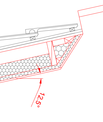
For the splay detail it's worth making sure your tile battens don't have to span too far so a nogging can take the bounce out. Also, if you are up on the roof giving the window a deep clean say then you don't want to damage the flashing if you step too near. For wider windows then the nogging has to be increased in size. This is a part detail but this mono pitch roof has timber sarking boards, counter batten, batten and breathable membrane. The fillet at ceiling level gives you a wider target for fixing the insulated plaster board at the bottom of the splay and you can maintain the minimum edge distance for the plasterboard fixings.
- 19 replies
-
- 1
-

-
- plasterboard
- drywall
- (and 3 more)
-
Structural Engineer Not Providing Connection Detail
Gus Potter replied to SteveMack's topic in General Structural Issues
Good points from all. It's worth asking the question whether the connection design is included or not. For domestic applications don't forget that although the beam sizes may be fairly small, the connections are also small so you can develop pretty high stress etc in these. Typically stress is calculated by Force / Area ... so small force / small area leads to the same/ similar stress concentration as ~ Big force / Big area. A good number of frame analyses packages (this is a bit of software that allows you to join all the beams etc together and quickly calculate the forces / deflection etc ) have a bolt on connection design module. This module allows you to design the connections and export the connection detail to another cad package or just print it out along with the calculations. The main thing is you need to know enough / have experience to make sure that what the software is printing out is not rubbish! A good thing here is that you can play about and tweek a connection to say fit in with the Architectural detail, or you may be forming a big slapping in a wall for a set of bifolds. Here you may have some torsional forces (twisting) in a connection which you can't avoid and the look up tables don't work for this. The software does the donkey work and you can then modify the calculations to suit. I find that there are a good few fabricators, partcularly smaller ones who don't have their own in house SE's (or are just too busy) to spend time connection designing on a small job. If you can hand it to them on a plate where they can just pass it to the shop floor you can make savings that offset (sometimes more) the extra SE cost. For domestic stuff a local SE will say know the local fabricators, how they like to work and play to their strengths and this can bring the cost in the round down. For the unwary.. connections don't always play fair! For example you may think that if you have a detail that shows a 8mm thick plate and you swap this for a 20mm thick plate (thinking it must be better) you have lying about this can suddenly make the connection much stiffer as the 20mm plate is less flexible than the 8mm plate, now you can overstress the welds and welds are often not as ductile (stretchy) as say the steel in the beam.. so you can get a sudden failure. An easy way of looking at this is if you take a ruler and support each end on a small bit of copper pipe, load it in the middle, the ruler bends and the ends rotate on the pipe, call this a pinned connection. All the pipe needs to do is carry half the vertical load you apply to the ruler. Now if you fix each end of the ruler to the pipe (which could actually be a column) it will bend less in the middle but this fixity at then ends introduces a "rotational" force called a moment as well. Now you have a moment connection. Here the top surface of the ruler is in tension, the bottom in compression. You can now see that the end connection has to deal with an extra force that can be quite substancial. On a lastish point, I have found that the easier you make it for a small builder fabricator on particularly domestic work the better in terms of cost. Yes, the SE may be a bit more expensive but the savings can be substancial. I always like to see the options explained in terms of the brief and this allows for an informed decision. -
Structural Engineer Not Providing Connection Detail
Gus Potter replied to SteveMack's topic in General Structural Issues
Hope it helped, although some of it was not specific to you. The main thing here is to keep talking to the SE. There may be an oversight in how the brief has been communicated to you and how you have interpreted it. Some fabricators can be a bit forthwrite too! It may be that a bit of give and take with the SE it will smooth the way. @SteveMack"Also, I wouldn’t mind if it was some simple connections I’d have a go as you suggest but they are all moment connections and 2 involve a 6m 305x305x198 uc connecting to a 400mm deep RHS which is holding up 80% of the gable end of the house. " I'm curious looking at the section sizes as to what you are doing. How all this is connected into the rest of the structure and given the sizes there may be some high loads, more likely you have some kind of sway resistant frame, I'm guessing though. The UC sections you have look huge for a domestic project unless you have a very big house. The SE may be using these sizes to reduce sway and have designed it as a portal frame with a pinned base connection. But, you can also do these as a box frame with side / top plates and this can reduce the weight of steel and spead the loads more evenly over the founds, more mangeable on site and much easier to drill etc to enable connection to the surrounding structure, thus less labour cost, more opportunity to use standard fixings, straps etc, make onsite adjustments when setting out errors occur, for example.. The SE should have provided clear detail showing how the frame is to be connected to the rest of the structure as this is also a safety critical aspect. The stability system is not something that fabricators generally touch. If this is not clear how the stability and restraint system works.. with all restraint fixings specified / detailed in such a way that it is applicable to your project then it's worth querying. If this detail is not robust then the SE may review and you may find that the issue you have resolves it's self. Just as an aside a 305 x 305 x 198 has a 31.4mm thick flange and a 19.1mm thick web. Consider how you can fix a brick tie say to something that thick, site drill it if you are the joiner with a battery drill and find say that the setting out is a bit off? Hope you can make some progess Steve, the builders may have some good ideas. -
Subtle Onoff. I would say port of the left (port side) where the hot should be, white on the right and go a mid postition ( Honeywell) valve for roseeeeeee

