Gus Potter
-
Posts
2339 -
Joined
-
Last visited
-
Days Won
29
Everything posted by Gus Potter
-
Pasquil Roof Trusses from Chorley
Gus Potter replied to jack1962's topic in General Self Build & DIY Discussion
Difficult times. If you have a simple roof although say loaded with attic rooms it might be worth looking at a traditional cut roof. Here you can use some simple steels or purlins at attic floor level to relieve some of the load. Much will depend on your circumstances but it's doable. Prefabricated trusses are generally made from a high grade timber TR26 and I have heard the big developers have "hoovered" it up. With a traditional roof you can go for a C16 or C24 timber that is maybe more "easily" available.. some weeks it is, some not, but at least you have time hopefully on your side and the reassurance that you have the material and that it belongs to you. The main thing is that you can spend time getting all your timber to site, store it carefully and then hopefully this will allow you to manage your progamme as you are less reliant on say cranes, delivery times of trusses and so on? Yes, it's not the most efficient way maybe, but in the round it may be worth a look even if to rule it out as an option. -
What Resin To Use For Resin Anchors
Gus Potter replied to Johnny Jekyll's topic in Building Materials
Conor. I'm left handed so went to check my spelling.. kindling.. these are the small sticks you use to light the stove say. Kidding is just friendly banter.. -
Pasquil Roof Trusses from Chorley
Gus Potter replied to jack1962's topic in General Self Build & DIY Discussion
Jack, you're making headway. Yes, It comes as no surprise to me that they have a "confidentaility" concern. I would not pelt the rep at this stage.. oh and if you are the rep reading this it's not something that you may be expected to know in great detail unless you have been designing and selling trusses for a long time. Jack you may wish to do the following. Write back in laymans terms and state that you bought the trusses from them as they are a CE approved fabricator (which I believe they state they hold) as you wished to be assured you were buying a quality and quality controlled product that complied with the Scottish Building Regulations.. You may wish to also say that it is your understanding their roof trusses are CE approved (look at the data badge for the CE mark) in the same way that structural steel must be supplied by a fabricator holding the CE mark as it is a legal statutory UK requirement, not least to ensure public safety. Make them an offer. Either come up with the technical information or you may contact trading standards, the HSE or the company that have oversight on their product approval. Be friendly but firm. Say you will be happy to maintain confidentiality as you just want to resolve the situation. Also say that you may or may not get your own SE to review the information they provide depending on whether they engage in a responsible manner. Make no mistake here. When it comes to structural safety it is a serious matter. A failure on their part to properly engage with you can have serious financial consequences for them coupled with a loss of reputation. You may also wish to mention that due to say the "shot through nails" that you have a concern that this may have weakend the timber locally and that you are also seeking to have these concerns addressed. Point out that you have lost "confidence" rightly or wrongly as the rep has back tracked on their "gap" 10mm now 1.5mm. Make no mistake here. When it comes to structural safety it is a serious matter. -
What Resin To Use For Resin Anchors
Gus Potter replied to Johnny Jekyll's topic in Building Materials
It's a thing you can recycle.. to light the fire with when the kindling has run out or the pages when there is no toilet roll. Just kidding. -
Pasquil Roof Trusses from Chorley
Gus Potter replied to jack1962's topic in General Self Build & DIY Discussion
Hello Jack. Yes there are tolerances..to some extent.. but it's a long topic. If you are not familiar with the in's and out's of truss manufacturing then one easy way is to turn the argument around when the rep comes and make them do the work. Yes they may be quoting the Eurocodes to you as they know it's not common bed time reading.. What you have here can be called a "lack of fit" in other words, there is a gap. When working in tension say the toothed nail connector is pulled tight.. often fine with a moderate lack of fit but when in compression.. a closer examination is required. Ask your rep to provide you with their test results / or SE sign off that demonstrates the gap you see is acceptable. Also ask them to provide you with the specific code clauses that deal with lack of fit. Explain you want to resolve this so it would be helpful if everyone is using the same hymn sheet and referring to the same clauses. If they can provide above info and show it is ok.. well should be ok? The gap is not horrendous so you may find all is ok. It's hard to give a definitive answer as much of truss connection design is by testing so each nail plate behaves in a different way. They are not keen to provide info as in some ways they are giving away their family silver.. testing and development costs a fortune. No, not really with modern software. The funny angle come from the fact that you are working to datums and this can throw up the funny angles on fabricated trusses. remember we are using computers to design and produce the data files for the machines that cut the timber.. it's not like a cut roof where you have a joiner with a set square. That said I would always aim to use standard pitches and so on as the slater / tiler and joiner still need to loose form the valleys, soffits and so on. Uddingston.. down the road from me so familiar with the factory to some extent. The gable ladders are still "hand build" where as the trusses are set on a "jig" on a very "sofisticated" bit of kit. Yes best to put work on hold until resolved if you can. -
What Resin To Use For Resin Anchors
Gus Potter replied to Johnny Jekyll's topic in Building Materials
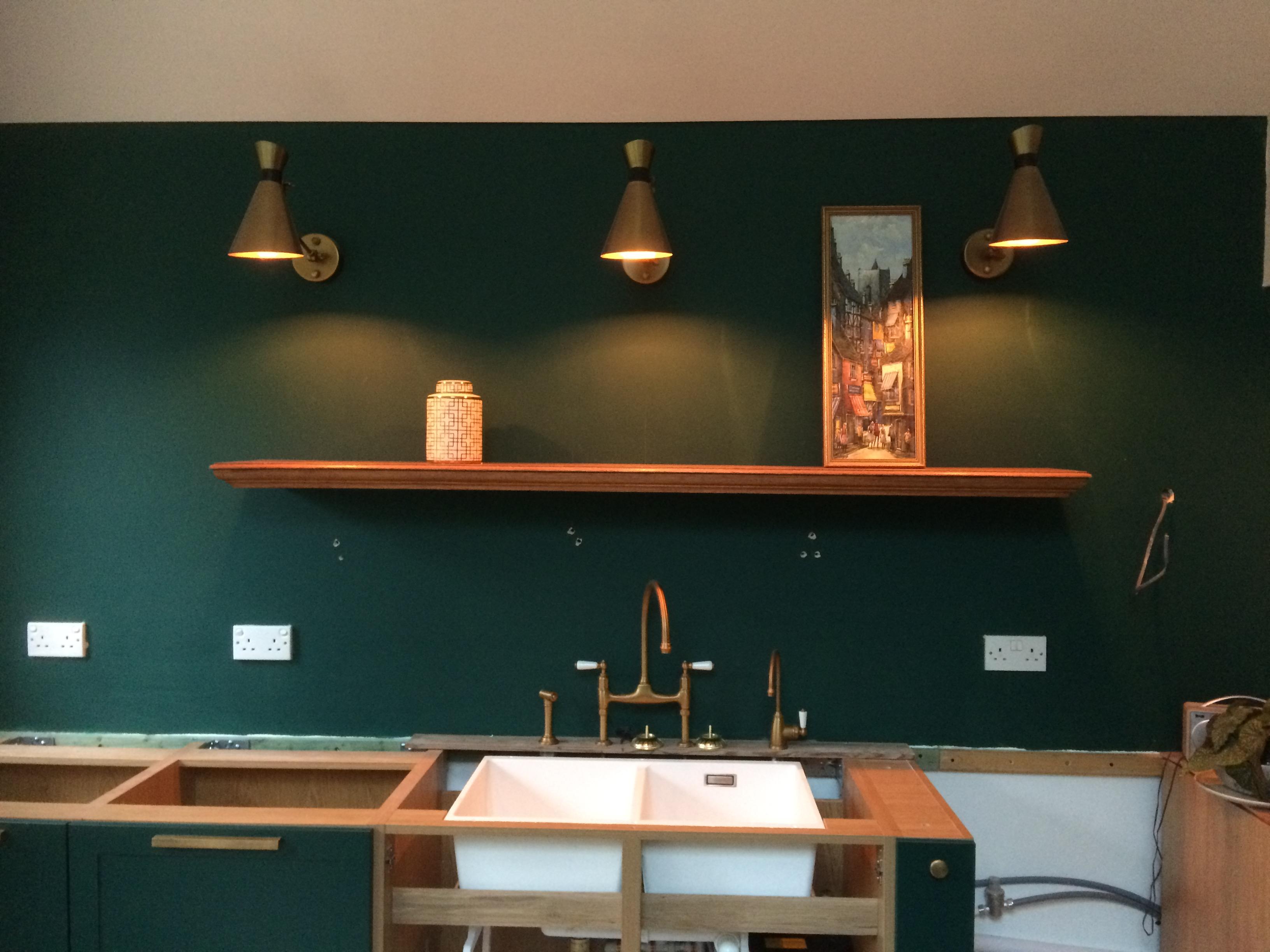
Bit of fun on using up extra resin anchors. Setting up part of the kitchen. The shelf is the top off an old oak sideboard. Will put a false base on it with some lighting to shine down on kitchen worktop and hide the rod /galv band ect. Rods are left over M12's that was used for anchoring structural stuff. Wall is 52.5 mm insulated plasterboard with 30mm of fire protection behind so 80mm of soft stuff. Holes below are test holes to find the studs. Drilled through the lot and about 40mm into the timber studs behind.. they (studs) can take this hole in this case structurally wise. Was going to put some resin in but thought let's try it by just putting a double lock nut on the end of the rod so I can turn the rod with a spanner.. and see if it the shelf will hold a bit of weight by just self tapping /threading it into the timber. It does so far! There is a little flex in it but not putting loads of books etc on the the shelf.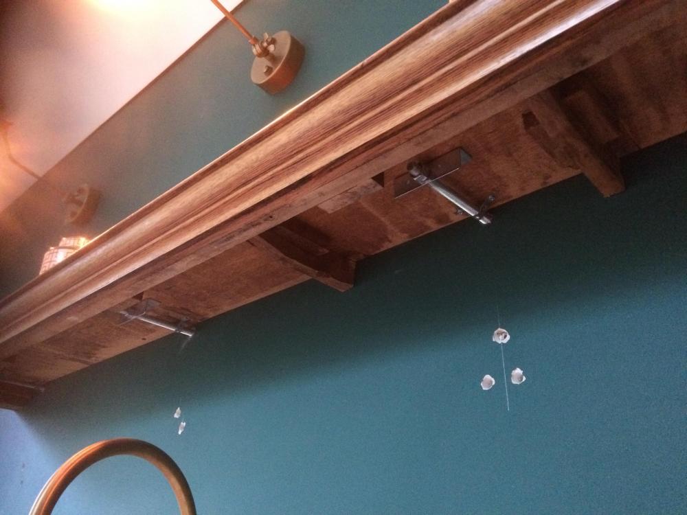

-
What Resin To Use For Resin Anchors
Gus Potter replied to Johnny Jekyll's topic in Building Materials
If you swap the bolts for rods cut to length on site just check what grade of bolt the SE has speced.. this could be 5.6 or say 8.8 grade. You can buy rod online say that is certified as being a particular grade. To avoid any hassle later on get a receipt that shows the grade of rod. If in any doubt get an 8.8 grade rod and nut to match as this usually covers all domestic applications. Some of the rods you get from DIY suppliers don't always have the grade specified and thus can appeal to the wallet at first glance. If you have rod left over this can come in useful to fix, for example floating shelves. -
How much can I safely store in my loft?
Gus Potter replied to vcps2021's topic in General Structural Issues
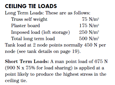
Yes looks like on the same page. The 25 kg per square metre your SE mentioned is shown in the "Ceiling Tie loads screen" shot as "Imposed load (loft storage) 250 N/m^2. Off this you deduct flooring weight to arrive at the figure of ~ 10 kg per square metre. -
Hiya Caroline P. Knocking out wall in flats is quite a subject. It's a great topic and not just relevant to folk with a "portfolio". I hope the following helps. If there is interest I'll make a post on the in's and outs of taking down walls in old stone built flats if you are say a first time buyer. For now Caroline.. The devil is in the detail, you say you have a "management company". That changes the game as if you are managing property, then you become an experienced client under the CDM regulations, it's difficult to argue with the HSE that you are just a domestic home owner. The law differs quite a lot. The next thing is, do you own the whole block or just all or part of the ground floor. Lastly, does the building connect to other buildings, say like tenements or a row of flats in a terrace. Now if you are taking out load bearing walls on a ground floor flat then the SE is going to ask: 1/ Who owns the other flats, or is the block in single ownership. 2/ Is the block connected to another block, do I need to take into account the stability of say a whole terrace of flats or is it a stand alone block. 3/ How do I discharge my statutory duty to public safety by ensuring that from conceptual design to completion and beyond (in service) the design and build is controlled and supervised. 4/ Can I be sure that I am working with a competant team who recognise that there has to be an element of the budget (5-10 % yes folks it's that much! ) set aside for health and safety as required by the statutory CDM regulations. Is there provision for contingency should we need to take action if something untoward happens. Who is authorised to take immediate action should something happen that is unexpected. 5/ The SE will want to know that the builder / contractor has not just public liability insurance but also full contracts works insurance. If they don't have this then the SE's PI insurance provider will run a mile, they will ask... Why is the SE working with builders that don't have a proven track record and industry standard insurance? Why should we take all the risk as the SE's insurers. It's worth while researching this as it could save you a pile of cash and also let you sleep at night knowing you are being safe, not inviting BC to serve you a notice and so on. Caroline, the above sounds a bit rough but that's kind of how things pan out. If this is more than a one off then your Dad and Husband probably need to get some proper contractors insurance, other than that they may be better off just doing the finishing work.
-
Just a thought. You have broker who must have some resonable relationship with the lender so that is positive. Try and establish the reasons for their sudden change of tack. Could it be that they have just taken a different view on how they view the presentation of your financial figures or is it something more fundamental. If it's the former then it may be a case of maybe realising some of your US assets into cash £ Sterling, providing security in a different way that is easier for the UK lender to call up under UK law and so on. It may just be a paper work excercise and you need to show that should you default then the lender can recover their monies quickly and efficiently. Put yourself in their shoes, that is how you win the battles. On the other hand it may be something more fundamental. The lender may be saying to themselves, hey look these folk seem to have plenty cash but once they start knocking things about, demolishing and so on the value that we can call on easily is only the value of the plot and that will be at a distressed sale price.. in other words what would the plot be worth at auction with a structure that could potentially incur demolition and clearing cost, then another journey through the planning system. Although you have equity the lender often thinks.. how easy will it be if these folk default to actually get our hands on the money and what will it cost us to do it if they resist! If it is the latter.. the plot thing, then your broker and designer should be able to help so don't feel alone here. It may just require a different sequencing of the works so that you hold more value in the plot and structure while adding to the value of the security. Yes it will be a pain to do, but it may only require a few tweeks to convince the underwriters that all will be ok. It's hard to predict what exactly will take place during the construction phase as this seems like a "renovation"? The sequencing that was origonally intended at lending stage may need to change due to site "conditions" .. that is a natural part of the construction process. Don't forget you are not alone, your broker will want to help. I imagine you have a designer.. Architect.. they will want to help to get the project off the ground. I'm sure you will find a way forward and later look back and say hey.. was a nighmare at the time but look at what we have achieved and do we not feel good!
-
Hello LSB. Don't worry, the confusion will wear off as you make progress, it's a learning curve, main thing is to enjoy the journey and drains are part of that! Lot's of good info already posted here for you to digest. To add a bit.. one helpful thing to do is to try and not make your treatment plant too deep under the ground. If you do then if the water table rises it has a tendency to float when you empty /clean it. Also, once you go below a certain depth (invert depth) for the tank it needs to be "stronger".. and these ones cost you more not just for the tank but the installation cost too. Your site (paddock) may have a slope so you need to make sure you can get the "Honeysuckle waggon" close enough and not too high above the tanks for cleaning. There is plenty info on the web from the tank suppliers, good laymans guides on this and how you comply with the regs in your local area regarding access, depths of tanks and water table level. You don't need for example to run the access road right up to the tank, but you can't have a bull in the field when the tanker driver comes..health and safety you see. If you have long runs say from the garden out to the paddock then you could look at using 110mm diameter pipe locally around the house. Then do a straight run to the paddock in 150mm diameter pipe carefully laid. Here you could have a 1:80 fall, less even. The LABC allude to the fact that you could achieve a 1:150 fall with a 150mm dia pipe! Fine, maybe not for me at 1:150 on a self build type project but I would ask the treatment plant supplier to give you a 150mm inlet so you don't get a restriction at the inlet to the tank. One way to figure it out is to draw it out to scale on a bit of say A3 paper. 60m run overall straight run say is not huge but it's still enough to make you think. I think with a little more research you'll find just the right solution for you. Using the 150mm pipe for the long run means that you probably only need a few simple 150mm couplings which are fairly cheep comparitively rather than lots of expensive bends and funny offset bends etc . save these for the smaller 110mm pipe around the house.
-
Good idea from Nod. So long as the span is say only over a doorway and the loads are not too high then as a one off it can work. I digress a bit..Have used this on renovations where you have say traditional solid stone walls 2ft thick.On the inside you put a heavier lintel then on the outside you use a solid steel plate, say 100mm wide x 25 - 30mm thk to just support the outer edge of the stonework. On the stone renovations I have gone for 304 grade stainless steel flats.. expensive though but it reduces the corrosion risk to the stonework. Deeno, the other thing to look at is to see if you can put the lintel (look at timber) within the rafter depth. The principle is the same as say trimming out for a velux window. Still probably cheeper than even a short length of 25 - 30mm thk stainless bar, but a mild steel flat bar protected by galv etc is a reasonable price. I would favour trying to trim a timber or two into the rafter depth first though, just make sure you check you are not compromising the ventilation of the roof.
-
How much can I safely store in my loft?
Gus Potter replied to vcps2021's topic in General Structural Issues
Hello all. Hope this helps give you some pointers for typical fink trusses, attic storage and what extra load you can put up there. The truss manufacturers often design to BS 6399 loadings unless told otherwise. Below is a typical example of the ceiling loads for an uninhabited attic. Roughly to convert N (Newtons) to kg you divide by 10. Thus an imposed load of 250 N/m^2 is 250/10 ~ 25kg per square metre. An imposed load can be your holiday stuff, hats and sun cream, or xmas decorations.. basically stuff that can get moved about and remember that you have to hold a heavy suitcase so there is you body weight to add. Now once you add in the weight of the chipboard flooring say 12 - 15 kg /m^2 = say 100 to 150 N/m^2 you are left with only being able to put about 10 to 15 kg of stuff up in the attic all spread out. Naw! really? You may ask.. I'm 15 stones (about 100kg ~ 1000 Newtons) so why does the ceiling not collapse when I go in the loft? Simplistically prefabricated trusses are designed to be as economic as possible. The truss manufacturers take advantage of the properties of timber which are different from steel. One key thing about timber is that is can carry a short term "shock load" like you at 15 stone without breaking. This is shown above as 900N ~ = 90 kg. You'll see an allowance of 75% for load sharing. This recognises that often you won't put all you weight on one bit of timber for any length of time and that there will be noggings (dwangs) and so on that shed some of the load to the adjacent timbers. But when a timber is loaded over a long time it starts to creep and is less able to sustain long term stresses, it is after all mostly celulose. You can see this in say old roofs that have sagged. This will also happen to your ceiling and can manifest in cracks. Also, as the timbers sag too much they can introduce other unwanted forces into the small nail plates (called second order effects) and they will "protest". Sometimes you can add a bit more load locally if you have some "load bearing" walls below, but let's be cautious for now. I'm not saying you can't start using your trussed rafter roof to carry extra load. There are a few ways you can simply strengthen some of these roofs. There is a temptation to start using the space more regularly, put electrical sockets in, maybe a bit of insulation. When you come to sell the Surveyor says.. hold on where are the permissions and calcs for all this. If you are going to put a more solid floor in please bear in in mind the above and make sure you can easily strip it all back out if need be. Please do not cut any trusses as this falls under BC regs and the scope of a building warrant in Scotland. One other point to bear in mind is this. While all may seem fine to begin with if you start pushing your luck and eating into the safety factors that were used in the truss design then you could get a serious failure when we get a big snow fall. It could be xmas time with a house full of kids! In summary if you have any doubt get an SE in, even if it is to reassure. Then enjoy your additional space.
-
Ask your SE how they feel about the following. Lift the existing boards, clean the top of the floor joists, wire brush , hoover the top so that you get a good rough clean surface. Apply a liberal amount of structural glue to top of joist. Pilot drill and counter sink holes in ply and screw fix down to top of joists at 200mm centres. Glue to be a true structural glue such as Cascamite.. not D4 as a popular on BH. The screws are to provide the compression while the glue hardens, the glue does the work. Now you have turned the joists into a quasi "T" beam. The SE will probably need to do some calcs by hand (a few pages mind) as you don't get off the shelf software for this, and also, as it's a bit off the wall they may need to spend some time "researching ".. great job for a graduate though wanting to build their portfolio as you have to go back to basics. Now you have your structural deck. Give it a bit of time to condition, get the heating working. Next tile but use a decoupling matt? ... plenty info on BH from the pro tilers on how you do it. Lastly make it clear to SE and Architect that you will accept any liability if the tiles crack and offer to pay SE as you have "heard" that it can be quite complex to design. The SE may just say.. oh I have an old spread sheet that I used to use, give me a couple of hundered quid and you take responsibility if tiles crack. On short span floor like this tile cracking is much more likely to occur due to shrinkage (drying and swelling) of the substrate rather than deflection of the structural members.
-
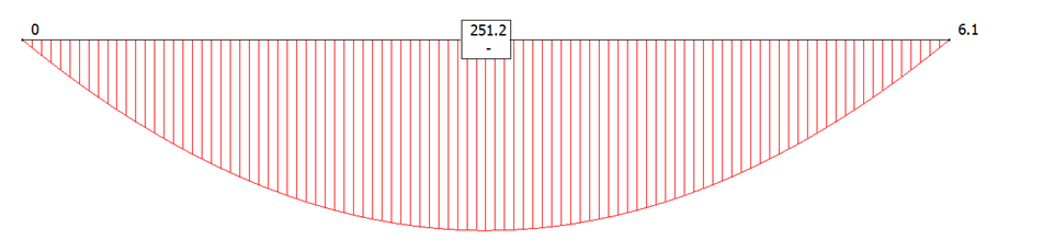
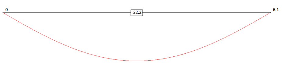
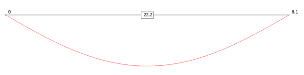
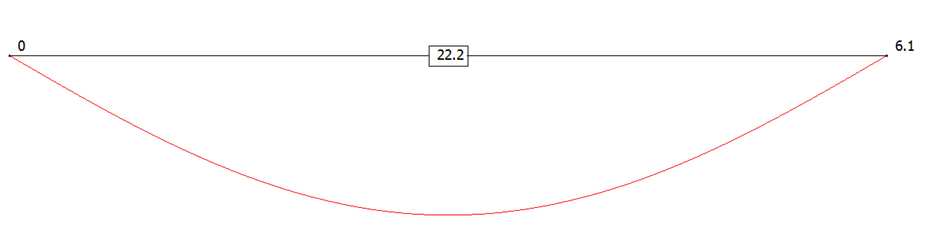
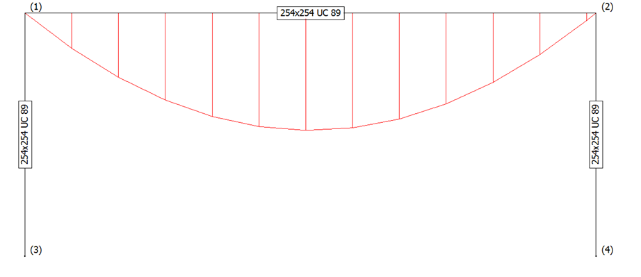
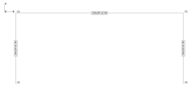
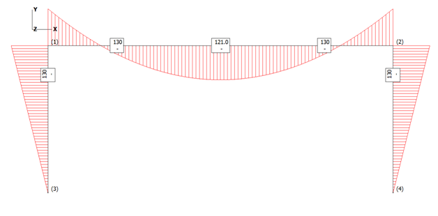
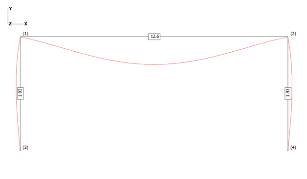
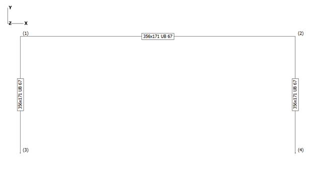
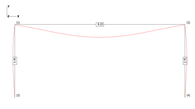
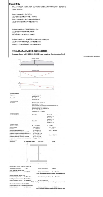
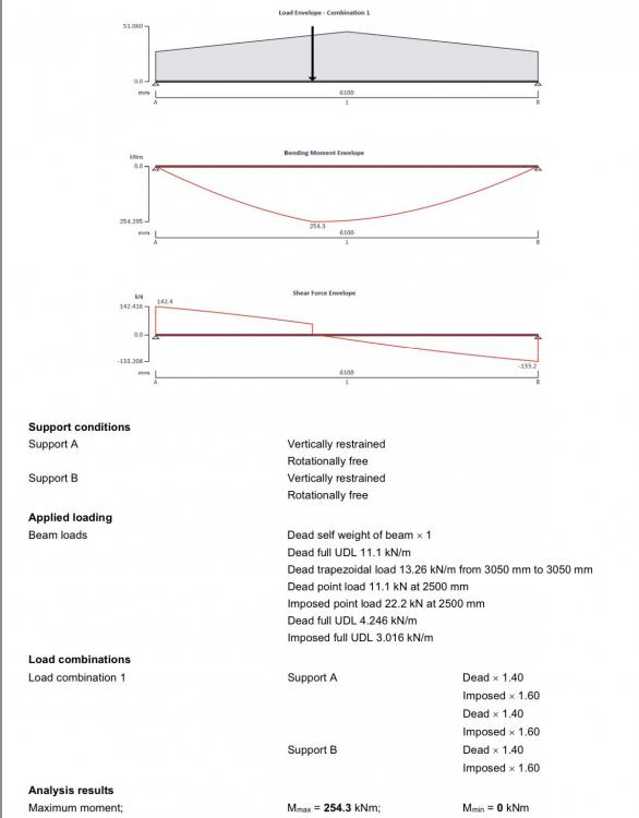
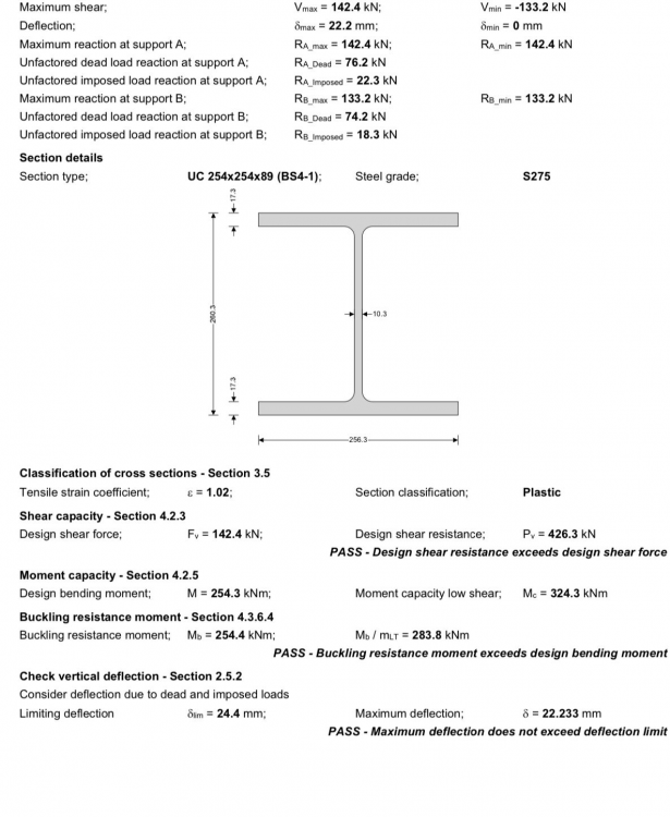
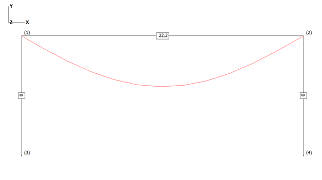
End of Cover Page Hello all and @Heather85uk Bifold doors, sliding doors, deflections and goal posts! Hopefully this part overview will help some BH members weave their way through what can be a bit of a mine field, but exciting too once they are installed and working! I have linked to Heather’s post as Heather has provided a few calcs (copied below) from the SE and in the spirit of BH I have taken the liberty of adapting and simplifying Heather’s calcs to “tell a story”. Heather, I hope you don’t mind. @Heather85uk There is plenty info on BH about limiting deflections and other good practical stuff, but I hope that it may be helpful to take a few steps back to see what causes these deflections and how you can start to get a design to work. Although the post is about bifolds, sliding door openings much of the following can be adapted by anyone who is contemplating making a hole in their house and needs a beam and/ or some columns to hold things up. Lastly, before the nitty gritty / the following is very much a simplification. Please don’t “ladle” into your SE as often there are other considerations to account for. Most SE’s should be willing to explain so just ask.. If they can see that you have put some effort into grasping some of the basics then they will often return the favour and more. Also, if you can get your head some of the concepts I hope it can help you get what you want at a reasonable price. Maybe, the following will give you more leverage when negotiating with door, glazing suppliers. To get started here I have taken Heather’s calcs and simplified the loads as it makes it (I hope) easier to get a feel for things. I have used these calcs as the deflections seem a bit “off”. A good refreshing thing I find about BH is that it’s a forum for solving potential problems. Heather’s calcs show a beam that is what we call simply supported. Imagine (I’ll ask this as this seems to be a common trait we share on BH) you have a ruler and prop each end on a pencil. Load it up and it bends. The pencils at each end allow the beam to rotate at the supports. This is called a “simple support” The diagram below is what we call a bending moment diagram and this represents the bending force in the beam (ruler). You can see that the largest bending force occurs in the middle, just like the ruler. You know intrinsically that if you overload the ruler over it’s length it will often tend to often snap in the middle where the largest bending force occurs. You can also see that the bending force is 251.2. The units are kilo Newton metres (kNm) and are close enough to Heather’s calcs for practical purposes. The diagram below is what we call the deflected shape. This is pretty much a representation of the shape the beam will take up when you load it. It’s a little different on the curve from Heather’s as I have converted the point loads to uniform loads. The deflection value of 22.2 mm is the amount the beam will bend in the middle and is close enough to the value shown in Heather’s calcs for the story! What we have above is similar behaviour to say a concrete lintel, a solid timber floor joist, a metal web joist and so on. The key thing to draw from this is that when a beam has a simple support at the ends it forms a shape like this and has a distribution of bending forces parabola shaped. If you have point loads then the parabola gets distorted to a greater or lesser extent. Heather mentions a “goal post”.. two uprights at each side and a beam over the top. Often you find that when you have a big opening you can get some onerous loads. Heather also has some point loads (maybe floor transfer beams framing in) near the middle of the beam span. Often you find that while you can get a beam to work, when you come to check the supports at the sides you find the masonry or timber frame holding up the ends of the beam can’t do the job. You can look on BH about pad stones, cripple studs and so on so I won’t explore further. One solution when the side supports can’t carry the loads is to introduce steel to form the sides, you form a “goal post” and take the load down to the foundations zone using steel which is good in compression, thus you relieve the load on say the masonry or timber frame at the sides of the opening. Steel is good at performing this function, but as there is no free lunch you often get more thermal bridging and you have to fix the steel to the rest of the structure, be mindful of that. Here (below diagram) the sides of the goal post only serve to transmit the vertical load and relieve the load say on the masonry or timber frame. I have replicated Heather’s beam below but with the same size of posts (columns) each side to form a goal post as it’s easier to make a point. “Don’t do this at home” as in detailed design you would balance the sections to match the bending and other forces and so on. The beam is still simply supported so you can see that all the columns are doing is acting like the “pencil supports” and holding up the ends of the beam. There is no bending force in the columns. They only carry the vertical loads from the beam ends down to the bottom of the goal post. The diagrams below show the bending moment diagram and the deflected shape. You can see that introducing the columns as simple supports has made no difference to the deflection. Still 22.2mm as we still have simple supports.. the pencils. We would hope that the ends of the beam and the columns are bolted (fixed) together in some way, if not you need to ask why not? But.. we can connect beams/ columns together in different ways. For example you can use a thin metal end plate on the top beam which bends like an elastic band (that is what I have done above and is called flexible connection) and then recovers (steel is quite bendy stuff!) so this maintains the idea of a pinned connection. Or, you can use a thick plate with bigger bolts, alter the welds etc. (if need be) which makes the connection rigid..a rigid connection. What I have done below is to keep the same arrangement of goal post / beam but changed the beam end connections from a pin to a more rigid connection. The first diagram shows the section sizes. Again, the sections I show are not quite what you do at the detailed design stage but I hope it makes the principles easier to follow. At detailed design you look to see what you can cut from stock lengths, the weight of steel and so on. The bending moment diagram below shows what happens when you change the end connection from a pin to a rigid connection.. Here you can see that by rigidly fixing the ends of the beam to the top of the columns we have reduced the bending effect in the middle of the beam and are asking the columns to now step up to the plate and do some extra work. The columns are now carrying some of the bending force as well as the vertical load from the ends of the beam. This relieves some of the bending force (moment) in the beam and this also reduces the deflection over the doors. Below is the deflected shape with the deflection value. By changing the type of connection at the end of the beam we have reduced the overall deflection from some 22.2mm down to 12.6mm. Getting closer to say Express Bifold deflection spec but still a bit off, but closer, nearly there! What we are doing here goes back to the ruler concept supported on a pencil at each end. If you had three hands then you’ll find that if you can stop the ends of the ruler rotating then it will bend (deflect) less in the middle. The columns act as two of your hands at each end of the ruler, imagine the third hand is applying the load to the ruler.. Nod, markc MickSharpe01 et al.. good points about beams sizes , the loads, hit and miss welding.. plenty good stuff to digest from them and others. Let’s now look at how you may go about getting something to work with Heather’s loads. Below I have picked all the same section / stock sizes, which means that you have a better chance of getting the connections to work and reduce wastage when you buy the steels.. go for the lightest weight of steel at the conceptual design stage and you’ll often run into trouble at the detailed connection design stage and it will end up costing you more. Often if you plump for the lightest beam then the flanges / webs are too thin to resist the localised forces from the bolts. You then end up having to design a complex connection with stiffeners, more bolts and the fabricator will charge you a lot for this extra work, often more than just starting out with a heavier off the shelf beam. As an aside. This is a good example for the self builder renovator. Sometimes it’s much better to go for the “simple stupid” .. stock steel sizes and simple connection design although initially you may feel you are using more steel. You should save money on fabrication and steel erection costs even though you may have to use heavier steels. Below is the deflected shape with the different (356 x171 x 67kg) set of sections. You can see that we are now down to some 9.2mm overall deflection. Yes, we have a bit more steel weight but we are looking for the easy way, stock items, that will also save on labour while considering that we are self builders rather than a large commercial outfit. What I have done above is to change some of the sections and connection types to show what you can do. The top beam is deeper and I have reduced the deflection down to 9.2mm over the 6.1m span. Feeling hopeful! Heather’s loading is roughly split (before applying safety factors) 50 /50 between live and dead loading. This means that as you are building the beam it will bend as you build up the floors and add the walls over the beam. Before you place the order for the doors you want to make sure you know the true opening as built sizes which will include the dead load deflection. Remember here.. your need to cut the brickie some slack. If they can get each side of the opening level to within 5.0mm that is good. A good brickie should be able to sweeten out the coursing too over the beam. Lastly we are using hot rolled steel beams. These too have a manufacturing tolerance and are not truly straight! Bearing the above in mind. Half of the 9.2mm deflection will take place before you order the doors. The other ~ 4.6mm when say it snows or you have a massive party and load up all the floors with live load. Express say 3.0mm not far off the 4.6mm! But the 25mm in Heather’s calcs? Hopefully the above has given you a flavour of goal posts and what you can do. Now one other thing that crops up in Heather’s calcs is a fairly high loading on the beam for a domestic application. You’ll see this in the calcs as being 142 kN. That is about 14 tonnes. This load is expressed as including the safety factors. Without the safety factors the load at the end of the beam will be about 100kN.. that is ten tonnes.. 10 old Volvo cars, not a small load. The load has to be carried by the founds. I hope this helps folk get a feel for goal posts! If you have an old house or say a house on piles and want to form a large opening then you can take the above principles and turn the goal post into a box frame. A box frame can also further reduce the top beam deflection and spread the load on the founds. In simplistic terms you take the load from above, down the sides of the goal post into a stiff bottom beam. This beam spreads the column loads out so the old founds “still think” they have the old wall above. Box frames are also good at resisting the sideways wind loads. I’ll leave that topic for now.. a story for another day if there is any interest. Hope this helps to give you some pointers and all the best with your journey.


- 3 replies
-
- 4
-

-

-
- bifolds
- deflection
- (and 1 more)
-
Ah.. When the builder lowered the levels did they alert you to the fact that you have corbelled brick found? Looks like you (builder) has excavated a tad more than you should have? Remember that external walls tend to hold up the roof too! I would ask an SE to have a look and at the same time they may sort out your screed levels. Sorry.
-
@cian It depends on what you want to do. Are you having to move to London due to say work or do you just want to chase the dragon of making money on property. Unless you have some serious funds behind you, local London contacts it could be a tough ride if you go at it the wrong way. You are really are entering the den when you play with the London boys / girls / etc ! There are a few folk on BH who have London experience.. I think! However, if you take a pragmatic view it can be great fun and rewarding. Cian. Maybe get some experience of self building / renovating a flat not in London if you can. Turn a profit on that before you stake the big bucks. Prove to yourself that you can develop something off your own back, turn a profit without relying on rising proprety values. That is the test! Do that, gain experience and you are on your way. It's also about the contacts you make. Build trust with a few trades folk, pay on time, they will return the favour..take you seriously.. introduce you to their contacts such as.. Plumbers, Sparks. the skip hire folk.. Once you get a network like this in place and have worked at it then you can look at the next stage with less risk of losing your shirt.
-
Deflection of 25mm from SE, problem for sliding doors
Gus Potter replied to Heather85uk's topic in RSJs, Lintels & Steelwork
Hello Heather85uk. No need. This subject crops up on BH a fair bit. The calcs raise a number of questions and you mention that the steel section is part of a goal post. There are a few permutations of "goalposts" and each permutation can influence the deflection and the choice of beam depth / width and so on. I think you need to take a few steps back first to be able to understand more of the principles, then you can go back to your SE with a bit more knowledge and ask why you have what you have. For example I can see that the beam is designed as simply supported, but why? The deflection is shown as overall deflection but is not split out into live and dead load defection and so on. If you wish can you provide a bit more info. It would be helpful know what is forming the posts each side and what they rest on at the bottom. Maybe a cross section that shows the wall thickness, buildup and materials. Also are your founds cast and how far have you got with say building the substructure? Are there height restrictions on the beam depth over the doors? Although this topic has been explored to some extent on BH if I can I'll write a general post over the weekend that explains more about the structural behaviour of the different types of goal post arrangement for those who are less familiar with the subject, how the different permutations influence the deflections, twisting effects and so on. I'll try and tailor it to your situation if possible and hopefully this will help you find the right solution for your build stage. You may have already read this thread on BH about door deflections. -
Legit to shorten a galvanized roofing strap?
Gus Potter replied to epsilonGreedy's topic in Roofing, Tiling & Slating
Ok to shorten in terms of galvanising / corrosion. Think about it this way. Dive into you local B&Q say, look at where they have had to drill the extra odd hole in the galvanised purlins to hang a banner / AC unit.. the SE's etc are not all round in droves. Just make sure that if you are shortening it you are not reducing it's intended tying capacity. Check the nailing specification and so on. -
No good outcome as they are all into identity politics and some other stuff that does not fit with a modern democracy. For a while I was an advocate for nuclear, great base load capacity until I designed an air cleaning plant housing structure for the decomissioning of Bradwell Power Station. The decomissioning costs are truly horrendous, not just for our kids but our kids kids if you want to do it in a safe way. Hydrogen may well work out but there are many things to develop. Take the basic boiler burner, the flame speed is much faster. The molecules are smaller so we will get a good few accidents due to leaks. Yes we can extract hydrogen from natural gas but we generate some not so nice by products that we need to deal with. Although much was made about Scotland being the "wind capital of the world" the reality is that the shallow off shore waters off the Southern part of the UK are currently more cost / carbon effective. For example the transmission losses are reduced that is why we build power stations close to the centre of population density. However Scotland has a lot of good water that could be pumped / syphoned using the earth's gravity to the South where there is the demand to produce the good grain etc. It's also about sharing our UK resources in a practical way in the short term. There is no doubt that we will improve the efficiency of ground source heat pumps but if every one puts one in their back garden (if you are wealthy enough to afford a garden) then what will the Blackbirds eat? The grass won't grow, there will be fewer worms for the birds chicks? Chill the ground and you invite the unforseen. The reality for me is that unless you get China / USA to change, anything we do needs to be done in such a way so as not to reduce our financial clout on the world stage. If we have no "buying power" then no one will listen to us? It is going to take a brave set of polititians to grasp this nettle, we may, I think need to wait for something really bad to happen before we get real action rather than the gesture politics we see at the moment.
-
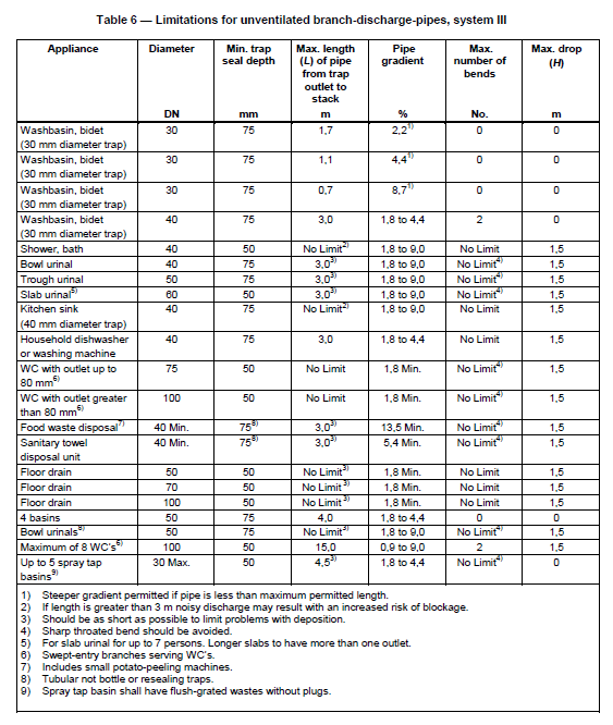
In almost all cases for a domestic dwelling (not flats which often share a common stack) it is a BC requirement. Here is some info which I hope helps BH members. In Scotland for example the regs point you to BS EN 12056 part 2 which is to do with drainage inside buildings. Comply with this code and you are well on your way to complying with the regs. There used to be great stuff and diagrams in the regs to help self builders /renovators but these are getting progressivly stripped out. Here are a few thoughs / observations. If you get a feel for the principles then you can adapt to suit your needs. Often you see a drain pipe poking out the roof..with a grill on top to prevent birds nesting and so on.. the top of the main stack. This open vent serves two purposes. One is to prevent excessive suction building up in the main drain line serving your house the other is to prevent over pressure in the line which will blow the traps.. and worse. Pressure can build up in a main drain line; if the wind is blowing the wrong way down stream (other folk doing daft things like facing a vent stack into the wind), if you have a blockage and a build up of gas (could be a gas leak too and the gas migrates into the drain! nice to vent outside than into your house) down stream if say your neighbour has been putting nappies down the drain. They get the drain folk in and they put a pressure washer down the pipe.. I'll leave the rest of the description for now as to much information can be uncomfortable. Commonly though it's suction that causes the issue. There are a number of ways you can design a drainage system. Some work on what we call "full bore flow" this is more common in the EU except for some roof drainage systems in the UK... you often see these full bore roof systems described as "syphonic systems" in the UK, some toilets work this way but just within the "bowl". Mainly though in the UK we design the drains in our houses (system iii) to not run full bore and thus they don't generate this true syphonic effect. But they do still generate some negative /positive pressure. When you pull the plug on the bath the water flows and pretty much fills the pipe. As the water moves down the pipe it compresses the air in front of it. If you don't relieve this compression it can blow the traps on say a sink in another room and thus fumes will enter that room. Some air passes over the top of the water in the pipe as it is not running full bore but often not enough. Commonly a sink trap has a shallow seal of water so we are only taking about a small amount of pressure, much less than say a car tyre or you blowing up a balloon. Once the bath is nearly empty if the pipe run is long then you have this body of water still moving down the pipe and this creates a suction effect behind it which keeps drawing water. This "residual suction" can be enough to stop the bath trap from filling properly at the end of the drain cycle and not creating a proper water seal. This means that when you say next flush the toilet the smells come out the bath trap rather than venting out through the stack. If the seal is completely broken (the trap is not filled enough) then you invite "lingering" odours from your own house and that of your neighbours unless you have your own private sewage system, in which case it's you own personal "gas". One way we get around this is to fit an air admittance valve on branch lines, say on a long run to a kitchen sink or ensuite bathroom. This works a bit like a snorkle in reverse. It is sensitive enough to let air in but not pressure (smells) out. This allows the trap to fill properly from say the last bit of water in the bath and create a seal. Now one problem arises with AAV's is that the regs require them to be set above the level of the spill over point. For example in a bathroom the idea is that the home owner will see the sink spilling over if they have a blockage rather than the AAV leaking and causing hidden damage. Now that all makes common sense. Some of the building regs are really good! But this does not fit well with modern bathroom and kitchen design as no one seems to want a "box in the corner" of their new sleek vanity unit or kitchen work top. I mentioned adapting previously. Sometimes you can implement an old solution that was commonly found in tenement flats. This is called a "loop vent". Here you create a circuit of pipe in a loop. The top part of the loop does not carry water, it just lets air circulate. Have a look on the internet for loop vent design.. kitchen designers with island units have picked up on this, reinvented the wheel and are punting this as some kind of great new invention. Ashthekid.. hope this give you and BH folk some background info. Oh, and there have been a few other posts on BH about pipe gradients etc...
-
Can you turn the cross walls into load bearing walls? It already sounds like you are intending that the cross walls should provide lateral stability to the external walls. i.e they are shear walls. Build these in timber frame if you like. Roughly where the ceiling ties join the rafters can you stick in a purlin running in the direction parallel to the long walls? The purlin is supported on the cross walls. The purlin can sit above or below the node point to the ceiling tie / rafter. These purlins take out all the spread out of the roof and carry the majority of the vertical load. Not you have relieved most of the load off wall that is causing problems and you can work on it as and when you like. It's (the ropey wall) pretty much left to carry it's own self weight and a small portion of rafter load from the bottom two or three feet of slates / sarking. The same principles can be used for loft conversions where the roof is required to carry heavier loads. This may work fine or you can often adapt the principle to suit the layout.
-
Hello Rob. There are no daft questions, it's daft not to ask in fact. I hope this helps to add to your research knowledge. To add to the great informative comments from other posts I'll touch on the structural side of things. I'll do a bit of general stuff first (tell a story) and then focus a bit on what you have. A bit of background on agricultural buildings... lets go "back to the second world war" Very roughly.. and there are a good few bits missing from the following but I've written this to take you hopefully on the "Build Hub Journey" When this war started the steel industry were a bit more advanced in the quality of the material they were producing. They went to Churchill (well not him really but it sounds good) and said.. look we need steel for the war effort. We have moved on from making steel in our back garden and now have "quality control" so our steel is more reliable and less varaible in quality. As it is less variable allow us to reduce the factors of safety we need to apply. This way we will use less steel for building domestic structures and there will be more available for making tanks etc. I will stand corrected but the Gov said OK. Now the concrete folk said...hang on that's not fair as we are all at war.. let us too reduce our safety factors..but they were still making concrete in their "back garden". In essence in a war situation Chuchhill said OK although there was no rational safety basis for doing so. The only basis was that we were in a war.. frankly, if we had lost it we would have much more to worry about than safety factors of concrete and steel design. Moving on..Rationing was still in place after the war and for a while folk still had ration cards, eating powdered eggs and so on. Folk wanted to see some improvement.. There was a push to mechanise farms, improve production. farmers made hay. Barns were needed to house grains and live stock. No one gave two hoots about the quality of the barn stuctures as the populase were restless and demanded a higher standard of diet. The demand was immediate not least politically. Over the next few decades the insurance industry clocked that they were having to shell out for barns say that were say "falling down" too often. Maybe they woke up to the fact that farmers are quite canny, were stuffing them and "having a laugh".. One part of the solution was to start to bring agicultural barns into the "building regs" They started to codify the design. One other driver for this was also that a lot of kids / young men were getting killed on farms back then. It was what we would call today "carnage" What then happened to some extent was that the farmers went "mental" and said if you impose these regs on us the food price is going to go up. I think a compromise was reached where the farmers got a half way house and this manifests today in the modern agicultural code BS 5502 part 22.BS EN 5502. A key thing about this code is that agricultural building design is based on lower loadings, a lower what we call "occupancy rate" , and have no proscribed deflection limits..the amount it sways / deflection. Deflection is critical if you want to use the same frame for a house. It may not fall down but it will move so much that it will burst your cladding fixings and the place will leak like a sieve. Have a look at modern cladding systems, they all have caveats on deflection. If that is not enough then go back to the loadings and occupancy rates.. they are often not compatible with the regs for modern housing roof loads and so on. As an aside jump now to 1980's. Here (and it still happens from time to time) we were getting a lot of "fake sections" from Asia. They are hard to spot, they look like a BS standard sections.. put a micrometer on the flanges and they are thin! Also they had a lot of impurities in the steel which compromises the welding. They are a "shoogly peg" to hang your new house off. Rob and for all. In reality nine times out of ten you''ll find that the frames are of no use structurally. If you want to delve down an SE will want to look at the base connections, have to make safe assumptions on the quality of the steel / oak frame / timber / concrete degredation / the size of the founds. Then the SE has to look at whether they can sign off on the fact that what you have will last for another 50 years which is often a lender requirement. Also remember that in the case of timbers when you alter the ground level, moisture content and let in air you can promote decay in timbers. timbers buiried in the ground will last for hundreds if not thousands of years.. look at some of the old oak piles etc found in the Thames.. all good until you let the air get at them. To sum up. I would start out by investigating the ins and out's. It's a pity that the planners in some cases insist on the retention of a building frame that has no historic value and is no longer serviceable. They fail to recognise that by trying to retain a frame that has outlived it's service life is actually bad for the environment, can prevent young folk getting on the housing ladder and so on. Rob. Lastly you have a fair mix of frames and different constructions. If you want post some photos of the concrete clad frames.. would be interested to see what you have to work with. Oh and if you are converting an old barn there were just as many chancers cutting corners in the past as there are now so proceed with that in mind.
-
New Member from Cork Ireland building ICF House
Gus Potter replied to Blynchy's topic in Introduce Yourself
Hi Blynchy. BH is a huge resource. It's stunning how much real practical info is here. There is a great mix of folk here. You'll always learn something here. I do each time I visit. Sounds like you are starting out on a journey. Best thing to do is to try and get familiar with the search function on BH..it's not google.. not commercial (so far) so you can find some really eclectic and valuable stuff. You'll need to spend a bit of time raking about but in doing so you'll pick up info on a pile of stuff and the next steps once you get moving on the build. A bit of time spent here will probably save you a fortune. Don't forget that building something yourself should be fun too. All the best. -
Builder cut 4.5cm off joists due to floor level screw up
Gus Potter replied to Loz's topic in General Structural Issues
Hello all. A lot of the following is general info which I hope will be of help if your builder has not done what they should have, or "done what they think is helpful"..some builders do this.. believe it or not. There are a lot of young (still some older ones too) builders that are really keen to please and keen to do the right thing. Their heart is in the right place. Yes it's an interesting subject this..for a good number of reasons. Unfortunately for Loz.. it's Loz's house we are talking about / discussing. Loz.. I was prompted to make the post about the timber grade as for me this takes you back to basics, can take heat out of any potential situation. No point in looking at load span tables etc if you have done something that has changed the intergrity / "provenance" of a component on which the load span tables rely on. Loz.. you mention that the SE is friendly with the builder. This is a normal occurence. SE's / Architect's / Designers / M&E specialists and so on like to work with good builders.. and builders like to work with good designers that can resolve; unforseen on site issues, be able to design and specify easily available materials and so on. That eases the way for everyone.. Also remember that builders can often be members of professional bodies / have extensive professional knowledge. Just because they may wear "shorts to work" does not mean they are unprofessional or lack knowledge! In fact the last few designers I've talked to have all been in shorts! .. COVID you see. For designers and builders (major contractors too) trust and professional respect for each other is built up over time and this has value. In particular, it often drives down the cost to the Client and this is how you get repeat work and recommendation from a Client. Every one is a winner to some degree. In summary don't worry at this stage that the builder, SE, BC officer may have a good friendly relationship. This is far removed from what we would call a corrupt relationship..for which you can not only be stuck off a professional register but also invite a holiday for yourself at a location chosen by our Monarch. Loz and all. Often you find that you know something is not right.. you just know this as a lay person.. you don't need to be an SE say.. trust your gut and ask questions, as you are doing. Loz, the builder may know that too. At one end they may know about the timber grade etc and just tried to pull the wool over your eyes. If they do know about the timber grading it would be a new thing for me though.. Your SE should have some awareness. At the other end they (builder) may have thought they were doing a good thing and solving problems.. helping you out. @saveasteading "Agreed. Mistakes happen and it is sometimes reasonable to find a solution that does not inconvenience the builder. " To add a bit to saveasteading's point. I'll use an example, corollary here. You can often deal with a home warrantly provider who is giving you the "run around". Often you encounter arguements such as "well the cracking you see is visually acceptable" or "some amount of settlement always happens". Dig deep into this and the modern Euro codes introduce a way of designing where deflections and settlements are more open to interpretation provided the structure remains safe! What this means is that often the domestic home owner has an expectation that is not met.. the developer/ builder is off the hook to a large extent unless the home owner is willing to spend a lot making a counter argument. Loz..you could find yourself in the position where the onus falls on you to make the case showing that you may have a "bouncy floor" and or a ceiling that cracks in a few years time for example. One key to unlocking this is to find something that you can point to that has compromised the structural safety. This is non negotiable as it is a UK legal requirement. Nail this and you often find that all the other arguments made become mute. This gives you the big stick as often to fix a structural safety issue you have to strip out and reinstate. Basically you cut the feet from under them. Loz in your case this timber grading thing may be the key to resolving this. Now you have the big stick and you can decide how to use it. But go gentle, particularly if it's been a genuine mistake. Always remember that if you use the stick half way though a project then if you make a mistake later then the builder etc will probably return the favour with a bit extra! Always ask yourself "what is fair and reasonable behavour? Be wise. Loz..Here are a some choices the SE may have. 1/ Be competant to visually grade the timber in it's cut down state (old school stuff but can be done still), recheck the strength / deflection which will now probably fail on overall deflection and look at the vibration. Then produce the calcs and evidence followed by sign off. 2/ Get a certified person from a timber merchants / producer (grade it and then perform the above checks) to do it for them.. the rub will be to make sure that the visual grading will still also be CE compliant.. good luck to the SE on that one. 3/ Chuck in the towel and look for another solution. Loz.. as promised.. here is something worth exploring. If you can accept a small reduction in the ceiling height then bolt onto the sides of the joists you have new 195 x 45 timbers. Alternate which side you bolt the timbers to. Bolt them all the same, say on the left hand side and you will get a rolling effect which is not desirable. Your SE should know this but the builder possibly won't. For the technically minded this rolling effect will happen as you shift both the centre of gravity of the section and the shear centre of what is now a composite section. Loz looking at the floor you have the joist sizing is probably governed by what we call the bending moment and deflection. In other words are the joists strong enough in the middle not to snap under load as they get bent and are the joists stiff enough so that the floor does not bounce too much. Where the joists frame into the supporting walls then you have what is called "shear effects". There is a good chance that the SE can show that at the ends of the joists they will still be ok in shear even though they have been effectively notched on top. Simon mentions this too but unless you have some other loads acting on the floor from above it all may be fine when the SE checks the shear at the joist ends. To expand on other posts on doubling up joists and so on. On the practical side when you offer up the new joists put plenty glue on the top side so they stick to the flooring . Now get the builder to run upstairs and screw the flooring to the new smooth surface of the extra joists before the glue takes up.. this will mitigate the squeeks. Yes, you'll need new noggings mid span (dwangs) but that is a small price to pay. I think you could resolve this fairly easily. It won't cost too much cf knocking holes in the masonry, potential disturbance to the masonry, lifting the floor and so on. Often the key here is to find the big stick. Show you have one and avoid using it, mainly because you often still need to finish the job. Also, if your builder has just made a genuine mistake then it's a fair and moral thing to do. Lastly Loz if your SE comes back and says the joists are failing at the ends due to shear then there are other options open such as using a ledger piece and so on. To finish on a positive note. Many projects encounter problems which can be resolved with a will and in an equitable way.