Search the Community
Showing results for tags 'sliding door'.
Found 5 results
-
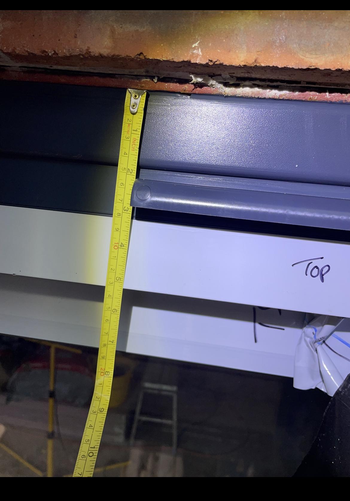
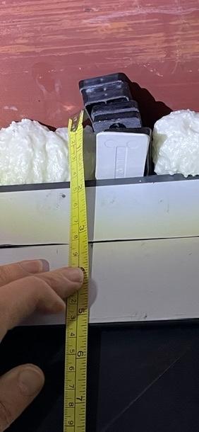
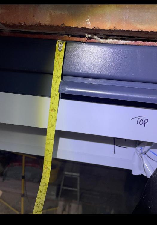
Hi, I'm new to the forum and introducing myself with our first issue. We are building a two storey extension and at the point of installing sliding doors. The floor isn't fully fitted but at the time of measuring there was the floorboards and steel in place. We are putting in ugh with tiles on top so knew the floor was going to increase by 40mm and we wanted a flush threshold so no runner to step over. Our issue is the gap at the top. We have a gap of approx 45mm between our steel and the trickle vent frame that sits on top of the main door frame. Is this excessive? to me I was expecting much less but window company say they have to allow tolerances for fitting, which I can understand but this much? What is your experience? I know inside can be improved visually as the plasterboard will go over, even though means less glass if the doors were measured correctly, but outside I'm left with the door frame, a 40mm trickle vent frame and then a 45mm cover. See pictures and can add more if needed. Would appreciate your views as they just keep saying tolerances, looks ok, to be expected and my expectations to high??? I would dispute this but am I being too high in expectations??
-
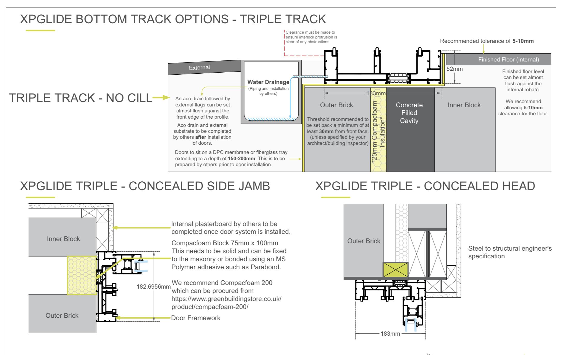
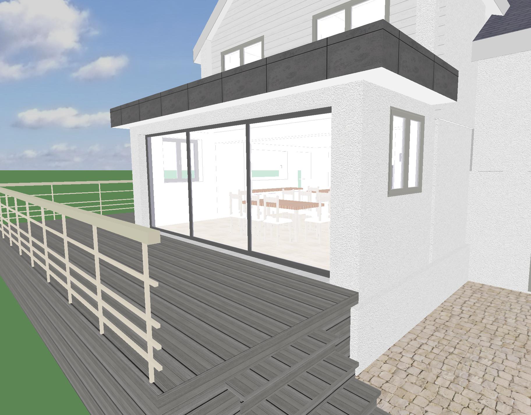
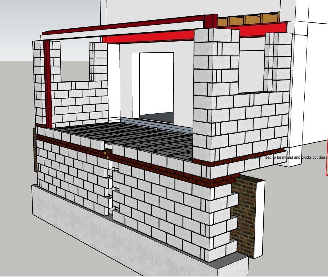
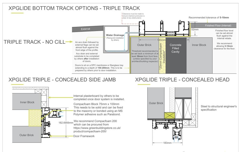
Hello, I'm self building an extension and I'd like help! First question: How do a get a level threshold and avoid thermal bridging with triple track sliding doors on a block and beam floor with a steel sway frame? A manufacturer has sent me this: But, none of those details match my own. I have Building Regs Approval (with Engineers calcs done) to build this: I've started "building" it in Sketchup:


-
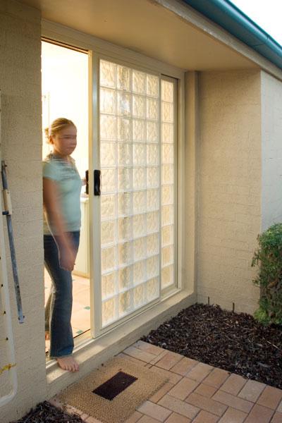
Does anybody in the U.K. make or produce sliding glass block doors? I’ve found one company, but unfortunately they’re in Australia! Something along the lines of this but for internal usage? Any other options or suggestions? https://www.blokup.com.au/gb_rb_075.htm
-
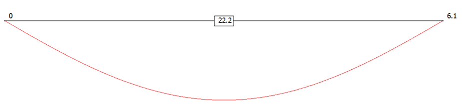
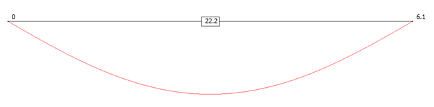
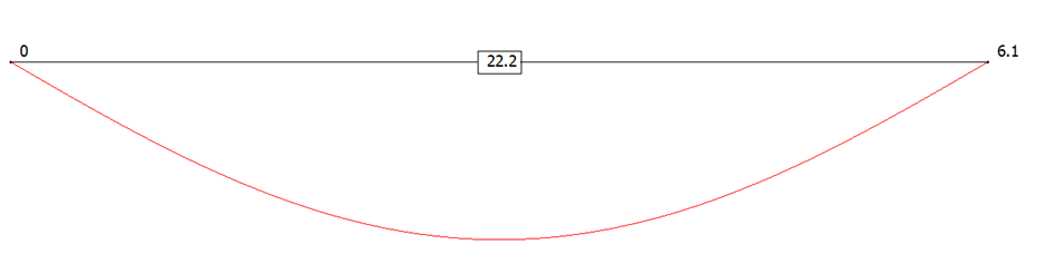
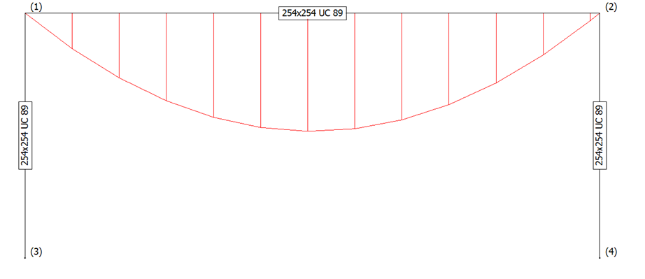
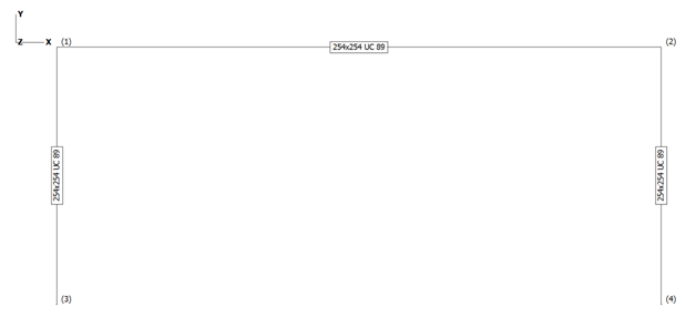
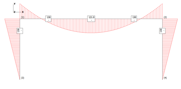
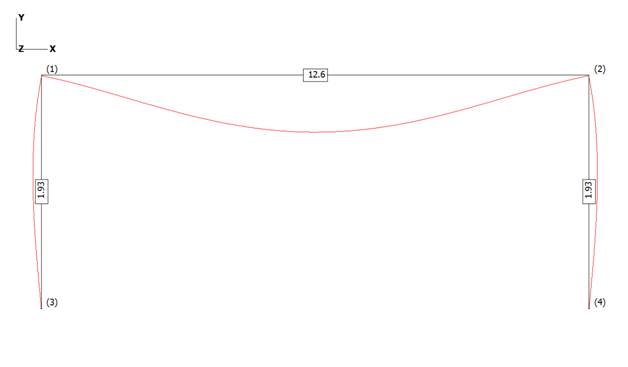
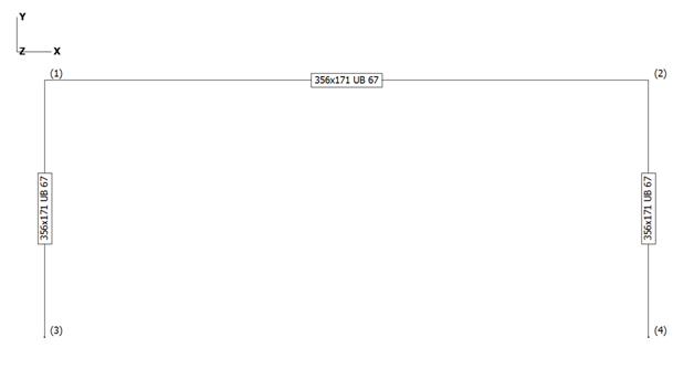
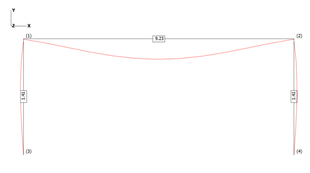
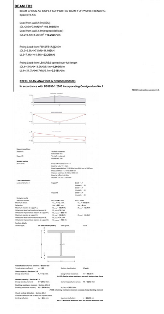
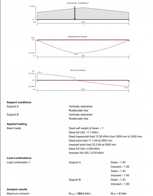
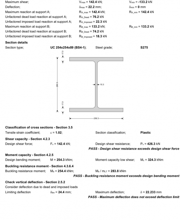
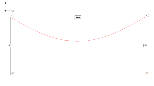
 End of Cover Page Hello all and @Heather85uk Bifold doors, sliding doors, deflections and goal posts! Hopefully this part overview will help some BH members weave their way through what can be a bit of a mine field, but exciting too once they are installed and working! I have linked to Heather’s post as Heather has provided a few calcs (copied below) from the SE and in the spirit of BH I have taken the liberty of adapting and simplifying Heather’s calcs to “tell a story”. Heather, I hope you don’t mind. @Heather85uk There is plenty info on BH about limiting deflections and other good practical stuff, but I hope that it may be helpful to take a few steps back to see what causes these deflections and how you can start to get a design to work. Although the post is about bifolds, sliding door openings much of the following can be adapted by anyone who is contemplating making a hole in their house and needs a beam and/ or some columns to hold things up. Lastly, before the nitty gritty / the following is very much a simplification. Please don’t “ladle” into your SE as often there are other considerations to account for. Most SE’s should be willing to explain so just ask.. If they can see that you have put some effort into grasping some of the basics then they will often return the favour and more. Also, if you can get your head some of the concepts I hope it can help you get what you want at a reasonable price. Maybe, the following will give you more leverage when negotiating with door, glazing suppliers. To get started here I have taken Heather’s calcs and simplified the loads as it makes it (I hope) easier to get a feel for things. I have used these calcs as the deflections seem a bit “off”. A good refreshing thing I find about BH is that it’s a forum for solving potential problems. Heather’s calcs show a beam that is what we call simply supported. Imagine (I’ll ask this as this seems to be a common trait we share on BH) you have a ruler and prop each end on a pencil. Load it up and it bends. The pencils at each end allow the beam to rotate at the supports. This is called a “simple support” The diagram below is what we call a bending moment diagram and this represents the bending force in the beam (ruler). You can see that the largest bending force occurs in the middle, just like the ruler. You know intrinsically that if you overload the ruler over it’s length it will often tend to often snap in the middle where the largest bending force occurs. You can also see that the bending force is 251.2. The units are kilo Newton metres (kNm) and are close enough to Heather’s calcs for practical purposes. The diagram below is what we call the deflected shape. This is pretty much a representation of the shape the beam will take up when you load it. It’s a little different on the curve from Heather’s as I have converted the point loads to uniform loads. The deflection value of 22.2 mm is the amount the beam will bend in the middle and is close enough to the value shown in Heather’s calcs for the story! What we have above is similar behaviour to say a concrete lintel, a solid timber floor joist, a metal web joist and so on. The key thing to draw from this is that when a beam has a simple support at the ends it forms a shape like this and has a distribution of bending forces parabola shaped. If you have point loads then the parabola gets distorted to a greater or lesser extent. Heather mentions a “goal post”.. two uprights at each side and a beam over the top. Often you find that when you have a big opening you can get some onerous loads. Heather also has some point loads (maybe floor transfer beams framing in) near the middle of the beam span. Often you find that while you can get a beam to work, when you come to check the supports at the sides you find the masonry or timber frame holding up the ends of the beam can’t do the job. You can look on BH about pad stones, cripple studs and so on so I won’t explore further. One solution when the side supports can’t carry the loads is to introduce steel to form the sides, you form a “goal post” and take the load down to the foundations zone using steel which is good in compression, thus you relieve the load on say the masonry or timber frame at the sides of the opening. Steel is good at performing this function, but as there is no free lunch you often get more thermal bridging and you have to fix the steel to the rest of the structure, be mindful of that. Here (below diagram) the sides of the goal post only serve to transmit the vertical load and relieve the load say on the masonry or timber frame. I have replicated Heather’s beam below but with the same size of posts (columns) each side to form a goal post as it’s easier to make a point. “Don’t do this at home” as in detailed design you would balance the sections to match the bending and other forces and so on. The beam is still simply supported so you can see that all the columns are doing is acting like the “pencil supports” and holding up the ends of the beam. There is no bending force in the columns. They only carry the vertical loads from the beam ends down to the bottom of the goal post. The diagrams below show the bending moment diagram and the deflected shape. You can see that introducing the columns as simple supports has made no difference to the deflection. Still 22.2mm as we still have simple supports.. the pencils. We would hope that the ends of the beam and the columns are bolted (fixed) together in some way, if not you need to ask why not? But.. we can connect beams/ columns together in different ways. For example you can use a thin metal end plate on the top beam which bends like an elastic band (that is what I have done above and is called flexible connection) and then recovers (steel is quite bendy stuff!) so this maintains the idea of a pinned connection. Or, you can use a thick plate with bigger bolts, alter the welds etc. (if need be) which makes the connection rigid..a rigid connection. What I have done below is to keep the same arrangement of goal post / beam but changed the beam end connections from a pin to a more rigid connection. The first diagram shows the section sizes. Again, the sections I show are not quite what you do at the detailed design stage but I hope it makes the principles easier to follow. At detailed design you look to see what you can cut from stock lengths, the weight of steel and so on. The bending moment diagram below shows what happens when you change the end connection from a pin to a rigid connection.. Here you can see that by rigidly fixing the ends of the beam to the top of the columns we have reduced the bending effect in the middle of the beam and are asking the columns to now step up to the plate and do some extra work. The columns are now carrying some of the bending force as well as the vertical load from the ends of the beam. This relieves some of the bending force (moment) in the beam and this also reduces the deflection over the doors. Below is the deflected shape with the deflection value. By changing the type of connection at the end of the beam we have reduced the overall deflection from some 22.2mm down to 12.6mm. Getting closer to say Express Bifold deflection spec but still a bit off, but closer, nearly there! What we are doing here goes back to the ruler concept supported on a pencil at each end. If you had three hands then you’ll find that if you can stop the ends of the ruler rotating then it will bend (deflect) less in the middle. The columns act as two of your hands at each end of the ruler, imagine the third hand is applying the load to the ruler.. Nod, markc MickSharpe01 et al.. good points about beams sizes , the loads, hit and miss welding.. plenty good stuff to digest from them and others. Let’s now look at how you may go about getting something to work with Heather’s loads. Below I have picked all the same section / stock sizes, which means that you have a better chance of getting the connections to work and reduce wastage when you buy the steels.. go for the lightest weight of steel at the conceptual design stage and you’ll often run into trouble at the detailed connection design stage and it will end up costing you more. Often if you plump for the lightest beam then the flanges / webs are too thin to resist the localised forces from the bolts. You then end up having to design a complex connection with stiffeners, more bolts and the fabricator will charge you a lot for this extra work, often more than just starting out with a heavier off the shelf beam. As an aside. This is a good example for the self builder renovator. Sometimes it’s much better to go for the “simple stupid” .. stock steel sizes and simple connection design although initially you may feel you are using more steel. You should save money on fabrication and steel erection costs even though you may have to use heavier steels. Below is the deflected shape with the different (356 x171 x 67kg) set of sections. You can see that we are now down to some 9.2mm overall deflection. Yes, we have a bit more steel weight but we are looking for the easy way, stock items, that will also save on labour while considering that we are self builders rather than a large commercial outfit. What I have done above is to change some of the sections and connection types to show what you can do. The top beam is deeper and I have reduced the deflection down to 9.2mm over the 6.1m span. Feeling hopeful! Heather’s loading is roughly split (before applying safety factors) 50 /50 between live and dead loading. This means that as you are building the beam it will bend as you build up the floors and add the walls over the beam. Before you place the order for the doors you want to make sure you know the true opening as built sizes which will include the dead load deflection. Remember here.. your need to cut the brickie some slack. If they can get each side of the opening level to within 5.0mm that is good. A good brickie should be able to sweeten out the coursing too over the beam. Lastly we are using hot rolled steel beams. These too have a manufacturing tolerance and are not truly straight! Bearing the above in mind. Half of the 9.2mm deflection will take place before you order the doors. The other ~ 4.6mm when say it snows or you have a massive party and load up all the floors with live load. Express say 3.0mm not far off the 4.6mm! But the 25mm in Heather’s calcs? Hopefully the above has given you a flavour of goal posts and what you can do. Now one other thing that crops up in Heather’s calcs is a fairly high loading on the beam for a domestic application. You’ll see this in the calcs as being 142 kN. That is about 14 tonnes. This load is expressed as including the safety factors. Without the safety factors the load at the end of the beam will be about 100kN.. that is ten tonnes.. 10 old Volvo cars, not a small load. The load has to be carried by the founds. I hope this helps folk get a feel for goal posts! If you have an old house or say a house on piles and want to form a large opening then you can take the above principles and turn the goal post into a box frame. A box frame can also further reduce the top beam deflection and spread the load on the founds. In simplistic terms you take the load from above, down the sides of the goal post into a stiff bottom beam. This beam spreads the column loads out so the old founds “still think” they have the old wall above. Box frames are also good at resisting the sideways wind loads. I’ll leave that topic for now.. a story for another day if there is any interest. Hope this helps to give you some pointers and all the best with your journey.
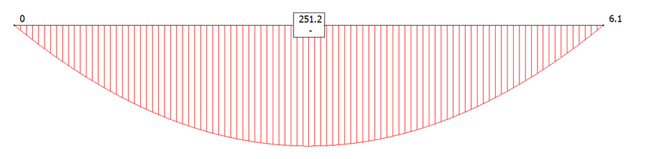


- 3 replies
-
- 4
-

-

-
- bifolds
- deflection
- (and 1 more)
-
We have quite a few pocket sliders in our build, they are great for bathrooms as they avoid the issue of having to accommodate an opening door, also have double sets between pairs of basement rooms to allow the rooms to open up. We were planning to use Eclisse and built our frames around their dimensions but then we discovered that they only do 3" or 4" studs and we have CLS, which is in-between. I then discovered http://www.hafele.co.uk/shop/home and got the correct sized sets for half the price of Eclisse - the frames are not as comprehensive as Eclisse but once clad in plasterboard they're fairly solid.