


Gus Potter
-
Posts
2339 -
Joined
-
Last visited
-
Days Won
29
Everything posted by Gus Potter
-
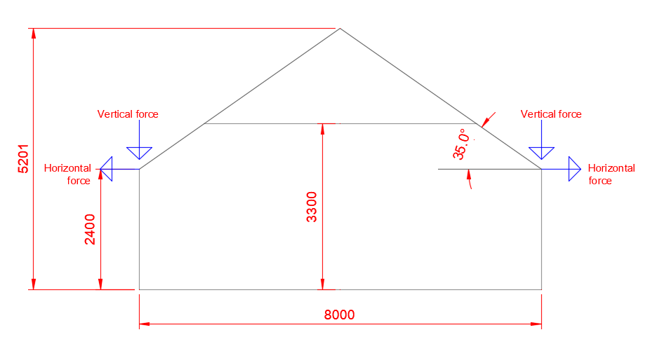
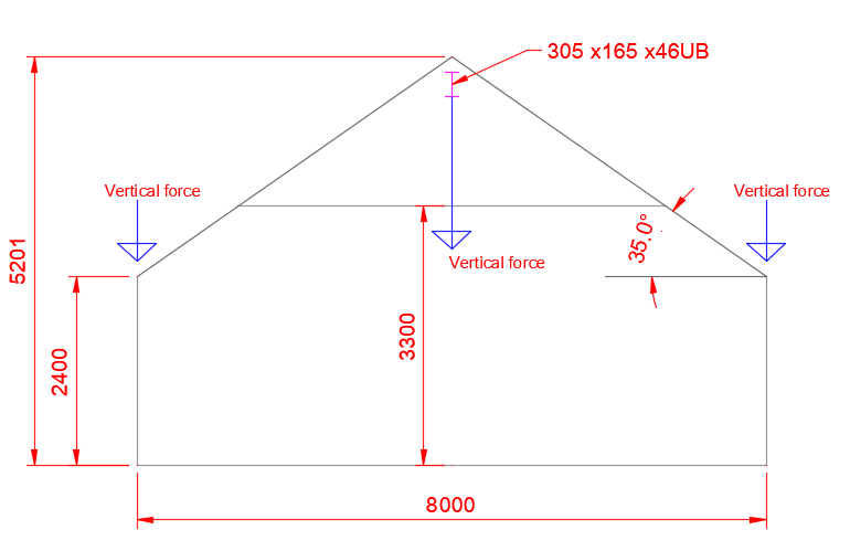
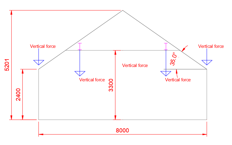
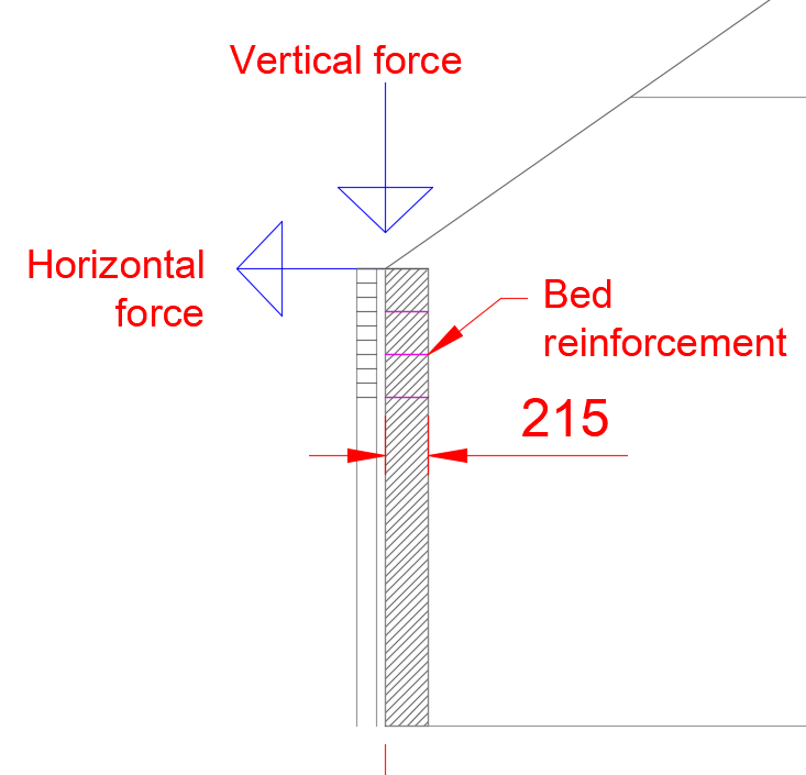
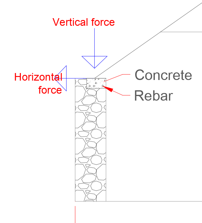
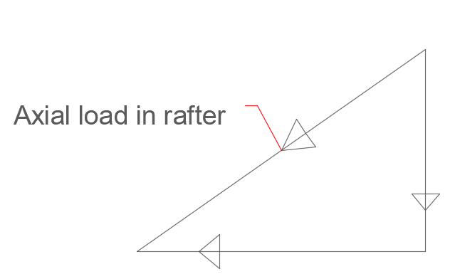
Hello JackofAll. Firstly all the best with your project and a tantalising question.. if you are that frame of mind. Hope the following is of some use to BH members. As a bit of background and as you haveJackofAll identified. Vaulted ceilings can introduce a sideways force into the head of the wall as the bottom part of the roof acts like a bit of a cantilever and bends like fury not just downwards but also moves sideways.. Masonry walls are good at carrying vertical loads but less able to resist horizontal loading particularly when the load is applied to the top via say a raised tie roof truss. JackofAll. To get the best out of BH post some drawings. But for now say you want to create an open plan space 6.0m long (call this the side elevation) with the trusses (a wooden roof) spanning 8.0m onto the 6.0m long walls. In other words the 6.0m long walls are 8.0 apart. I have picked a good size of room (but a bit of an odd shape) for ease of discussion. Let's also say that the 6.0m wall (side elevation) is 2.4m high and has no openings. The above is a stick diagram of one truss. And in the spirit of BH one of the things we are interested in is how much will it cost and what are the options. To cut a long storey short first look at how to mitigate the horizontal loading on the wall head. Say you have some decent gable walls tying into the side elevation walls and that these gable walls will support a beam at ridge level or somewhere along the gable length. Let's look at the economics of putting in say a steel universal beam(UB). Well all other things being equal I would say.. the room is 6.0m long.. 6000mm. My first stab at a sizing steel beam depth for a standard roof may be 6000 / 20 = 300mm.. draw a 305 x 146 x 46 kg per metre weight. It's got a nice wide flange for connecting timber to. May work but deflection, how much it bends by may be an issue but it's a start. I think that the beam is optomistic in depth (may need to increase the size) but.. it's for demo purposes at the moment. Maybe span / 15 would be a safe place to start.. 6000 / 15 = 400mm say a 406 x 178 x 60 UB.. ugly though! if you can't hide it. The beam is just a cut steel, say shot blasted and primed with a zinc rich primer. Say you are a first time builder buying a beam like this. Beam weight 60 kg x 6.0m = 360 kg @ 2K per tonne = £ 720 delivered.. prices will vary but compared with building much heavier walls and the loss of say floor space it's a drop in the bucket. And if that does not suit the mood music or the forces are a bit big then what about this.. Now it may be that putting in steels as above may just not be acceptable visually and we need the walls to resist the horizontal loading. Here it gets a bit more complex. As an aside a cavity width up to 300mm when using say the BS design codes say does not have that much effect on the strength of the walls. Even using block on the flat does help a bit but not as much as you would hope and.. it's a lot of money to spend building an extra thickness of wall just to resist the horizontal loading. Also, you can lose floor space which is expensive when you come to value a property. For all.. the above techniques can be used to convert your attic too! Sticking to the thread. Suppose we can't have any steels as Architecturally it just not acceptable. I deviate but it helps to explain a point. @saveasteading Saveasteading for example has posted a photo or two of a conversion that has solid stone walls. These massive walls can resist quite a lot of sideways load as they are so heavy.. it takes quite a lot to tip them over and this extra spare capacity can be used to resist the horizontal loading from the trusses in certain cases. That is why when you are doing a barn conversion that has solid stone walls you may wonder why is the old roof not spreading?.. it's because the walls are say 2 foot thick and very heavy. But modern construction is a different animal. We just can't afford to build walls 2 foot thick just to resist horizontal loading from the roof. Now lets turn to a modern cavity wall. Say the roof is supported by the inner leaf, could also be the outer leaf. We have a horizontal load from the roof. Now to resist this we could turn one of the leaves of the wall into a reinforced beam that spans horizontally between the gables.. along the top of the side elevation wall, by introducing say bed reinforcement. Looks great on paper but the brickies are not that keen on it and will charge you more. For the novice self builder it's hard to argue with a brickie, they are often grumpy. Also even with a 215 thick block on the flat the beam is too shallow.. only 215mm thick less the cover to the bed reinforcement.. it's hard to make something like this fly. Also, as soon as you start to form openings in the walls, put in lintels it all starts to get a bit complicated, often stops working in practice, you really need to control the quality of workmanship.. more money. Below is a sketch, in effect you are turning the top courses of masonry into a reinforced beam spanning gable to gable which resists the sideways loads from the roof. Turning back to / as an aside for the barn converters on BH @saveasteading Sometimes you can do this if you are faced with a choice between conservation and preservation. Solid stone walls can be a bit weak / weathered. You be may faced with a choice; conserve or preserve. Sometimes on balance you may conclude that the best route is to cast a perimeter concrete beam on the inside of the wall, you could also do this in a modern context but it is not cost effective. Lastly but not least JackofAll. There is another trick that you can look at if you just can't bear the thought of steels, glulam beams performing the functions shown in the above. For an overview. You'll see in the diagrams above I have indicated horizontal and vertical forces.. but we have a sloping rafter. There are a number of things going on in the rafter in terms of forces. For another day, but one major / dominant force is compression of the rafter (call this axial load) this is the compression load along the length of the short bit of rafter ( there is also a bending force and another force but ignore that for now) between the ceiling tie and the wall head. What I have done is to split this load into two forces.. horizontal and vertical. Now ignore the vertical and horizontal lines, imagine you are looking up from the gutter to the ridge, up the slope of the roof. Also imagine that the rafters are clad with a good thick well nailed sarking board or say an 18mm OSB / ply board. What you are looking at is a big deep beam from gutter to ridge that spans from gable to gable. Provided this beam is fixed to the gables then you don't load the side elevation walls horizontally so you can have a standard cavity wall. It takes a leap of faith and you need to detail the gable properly. This all works fine in principle provided you don't then go putting in massive skylights, velux in the roof.. we know if you cut holes in the web of a beam it weakens it. Small apertures carefully positioned.. fine.. be sensible. In Scotland they use sarking boards which help turn the roof into a deep beam in the plane of the roof as this helps for example stiffen the roof against the wind. Old steadings / barn roofs use the same principle. The sarking / bracing helps to turn the roof into a big beam in the plane of the rafter and this stiffens it all up and reduces the horizontal loading on the side elevation walls. What I describe is nothing new, these old builders have been doing this for hundreds of years. The key is to appreciate how you can construct roofs to shift the loads to where they can be easily dealt with. JackofAll. Hopefully you can take some of the info above and adapt it for your project. All the best.
-
fix sliding door header directly to steels?
Gus Potter replied to Tom's topic in General Self Build & DIY Discussion
Hello Tom. It would not be my first choice of option. You also mention the word cantilever! .. and that indicates that close examination is required. The starting point is to look at what the steel is holding up. How much dead weight is there that does not change and how much variable load could be applied to the steel (call this live load) as it is the live load that will cause the steel to move up and down... deflect. Sometimes a steel also has to resist wind uplift.. it can bend upwards too.. not often, but it can happen occasionaly depending on building geometry. The most probematic case is where the steel bends downwards and jambs the doors. Personally I would like to see some gap.. say 10 - 15mm to allow for a bit of play and to give the steel somewhere to go. Looking ahead if you do get a problem with the doors sticking you want to be sure that you could tweek the frame at a later date... if it's fixed hard to the steel this closes off some of your options when maintaining the doors. Just as an aside and for all. If you have a goal post frame..a column at each side and a header beam then if the connection is between the header beam and the column inner flange you can sometimes get bolt slip and this causes the header beam to drop a fraction. Clearly if the header beam is connected so that the beam rests on top of the columns this is not an issue for downwards loading. For a lot of steelwork we don't use what are called tension controlled bolts or High Strength Friction Grip bolts (HSFG) as it adds to the cost. These bolts are designed / intended to prevent slip amongst other things. We normally use Ordinary bolts in a hole with a +2.0mm hole in the steel. Thus if you are using a 16mm diameter bolt it goes in an 18mm hole. Now it may seem tight when you put it in but occasionally you may get a phone call saying "we have just heard a bang" is our building falling down? Sometimes it just means the steel has dropped a little and come to rest. But these high end doors are a bit sensitive and that may be enough to cause a problem. leave a gap and if the steels drop up to 1.0 mm after a hot summers day then the gap should head off sticky door issues at the pass. The other thing is that when it snows or you maybe get wind pressure on the roof forcing it downwards the steel moves up and down... it's just doing it's thing. Fix the doors to the steel and they too will have to follow this movement. Introduce a bit of "give" and it's one less stress that the doors frames need to cope with. Apparently less stress leads to a longer life! I would go for a gap between the steel and the top of the door frame even if you have bifolds which often need to be fitted tight top to bottom as it allows you to maintain in the long term. Say you have bifolds and one leaf fails, burst frame joint say. It may be that to get it all to work properly you need to adjust the door head a little.. fixed hard to the steel then what do you do next? Hope this helps you slumber. -
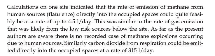
Zoot.. And a bit of MVHR for all.. Are you going to be living in this place on your own? Apparently an average human produces about 4oz of feaces a day... say 5oz following a big say curry so that's about 200 -250 grammes..or 5* 50 grammes at ten minute intervals if you have cooked it yourself and not washed your hands.. never taken the time to verify by testing myself but have a reference book that covers similar, same book also has an esimate of how much "human gas" is prevelant in and average family house per person. As it's Build Hub and in the interests of community knowledge I have copied below a paragraph from the Ground Gas Hand Book with ISBN reference for the really curious / sad. Yes this is something that you have to take into account when gas monitoring in some cases. For BH folk that were wondering about how much CO2 builds up when using MVHR systems here is a reference figure! 2009 Not sure what you are going to use the cottage for but if you expect to use it as a regular home (much worse if you want to rent it out as a holiday home) with more than one or two person occupancy then don't spend too much time money on the tank lid.. the soakaway and so on is going to give you the issues... and you'll probably need to get a new modern tank. Would be keen to hear what your doing to the rest of the cottage. All the best and have fun with your project. Oh technical note.. if you have the council coming round and saying they are checking for methane from mine workings then you need to look carefully to make sure they have allowed for the level of occupancy before they condem your house. It may or may not be relevant to you having to move out or not if you are border line.

-
Velux sun tunnel noisy in rain etc?
Gus Potter replied to Dan1983's topic in Skylights & Roof Windows
Good to hear you are making progress. Go for the light, don't like the sound then use a pillow! Much more expensive to retro fit and the disruption it causes to the tile work. My gut feeling is that you won't regret it.. oh and the romance of the rain / hail/ nasty weather when tucked up in bed (Barbara Cartland (9 July 1901 – 21 May 2000 ) I think. -
Bang on Peter. To dry it out in best way if you are short on time is to use a dehumidfier at night when the place is locked up, during the day get the wind blowing through it. Try to avoid drying the timber too fast as it will contort. Some will dry too much and some hardly at all. Fresh air is your friend!
-
Velux sun tunnel noisy in rain etc?
Gus Potter replied to Dan1983's topic in Skylights & Roof Windows
Hi Dan1983 I would always opt for a bright hall. Some plus points below. 1/ It's the first thing you and visitors see when you get home. 2/ If it's your forever home then as your eyes dim then good diffuse light helps a lot. 3/ You may want to sell and a dark hall can put some folk off a house as soon as they walk in the door. 4/ Lighting stairs is really important not just for safety but can accentuate features of a well designed and attractive stair. If would try if you can to get as much light in as you can, if the tunnel is noisy.. you will need good hearing for it to bug on a regular basis then stuff a pillow in it when you get the heavy rain showers in the autumn and spring with a bit of hail stones. You'll need to be able to access the tunnel from time to time as spiders always seem to find some way to get in. Of course light tunnels are not that cheep once you add in all the bits and bobs. -
What's buried in your build?
Gus Potter replied to Conor's topic in General Self Build & DIY Discussion
When I was a young builder we converted an old telephone exchange. The client had stored stuff in the main switchboard room, (was a massive space) and covered it up with a tarpaulin. Client then went to Australia for three months. On return client expressed delight at the progress of the works.. But.. noted that there was stored under tarpaulin are substancial lawn tractor which would now not fit out through the new door openings. Fortunately one of the guys was a Farmer and knew how to take it apart. -
Velux sun tunnel noisy in rain etc?
Gus Potter replied to Dan1983's topic in Skylights & Roof Windows
Don't know! But as the tube is fairly flexible you would expect that it should dampen the sound? You could also wrap the outside of the tube in glass wool to change the natural frequency and thus tendency to amplify the sound? Also, you have another cover at ceiling level, again which should help to reduce noise transmission. Alternatively is it just you that may be buged or both of you?.. great to lie in bed in a warm house and listen to the weather outside when it's wild. -
Paul & Maria, There you go. @saveasteading has chipped in with some expert advice!
-
It's a tough one, where and how do you spend your money? I have / do wrestle with this. One starting point is to ask.. what do you want the windows to do for you! Do you need lots of light, do you want thin frames, (say a set of sliding doors with thin 20mm thick mullions) do you need to comply with planning conditions, reduce noise or are you trying to use your windows to achieve a certain U value to make your scheme work? How long do you want your windows to last.. in other words is this your forever home or are you doing this as a step to something else? I'll leave it to you to moralise.. The windows/ doors are a big ticket item. Considerations for me are: 1/ Do you really need 3g? Is this for insulation or sound? If sound insulation then plus point, if just for insulation then can this be achieved with less long term risk..(say by spending your money on insulating elsewhere go for the simple stupid option) beyond the glass guarentee. Put three panes of glass together and they are heavy. The inner pane can heat up like fury as it is in it's own green house, lots of thermal expansion which stresses the seals. Then you probably have some argon gas that is supposed to not behave like a gas does and just stay put! 2/ The hinge and locking technology.. look carefully and you'll see that this has not developed as fast as we would like. Again fine for a few years but look at the size and embedment of the fixing screws in the hinges. It's a weak spot. Three panes of glass? Remember that some windows and doors will be opened a lot.. some on few occasions. Seriously have a look at the screws.. you can have some really high end windows with "tiny screws " .. it's a serious weak spot! 3/ What level of adjustment do you have in the locking mechanism. Take a tilt and turn window/ casement.. can you as a home owner adjust them yourselves after reading the instructions? 4/ How flexible are the seals? Well as a lay person unless you have a good knowledge of the materials that are used to form the seals you won't really know and your window supplier is not likely to tell you! But as a lay guide. Imagine you are sealing a shower tray on a bouncy timber floor. Put in a tiny bead of silicon (aka a small seal) and that tiny bead has to stretch a lot over a short length, put in a big thick bead ( heavy seal) and the stress is less as you have a longer length of bead. Same with your window seal, don't ask it to compress too much and it will return the favour in the long term. 5/ Overcladding timber with aluminium. All sounds good, warranty for say ten years.. but what about the windows performing for say 25 - 40 years? Like say a timber sash and case window that can be maintained with ease. It would be good and I would welcome info from the "Aluclad" type suppliers on their recommendations for long term durability and low cost maintenance in the long term. What do you do when you need to replace a hinge and have lost fixity / embedment of the screws? Yes these composite frames may be fine in Scandinavia but hey.. this is the UK.. we just don't get the low temperatures in the winter with the associated low humidity, we get British weather.. it's a different animal, wet, a bit cold but plenty water in the air. Covering wood with metal which seals moisture in? Really but how do you keep the joint watertight on the aluminium section in the long term when the substrate of timber is doing what wood does..? 6/ Now we all know that for timber to last it needs to breath. We have for a long time used cross laminated timber (CLT).. it's like plywood where you glue films /veneers of wood together. Engineered flooring is a good example.. we often use this when we have underfloor heating. Look at the UF heating specs for engineered flooring and they are quite clear that you need to control moisture, let the CLT breath. But suddenly the window folk are sealing one side at least with an impervious material? Once the water gets in what then? Much reliance seems to be placed on say the glue, how the timber is dried and the fact that the metal cladding will remain water tight. I am at a loss as to how this works in the long term given the different behavoirs of the wood and metal subject to varying moisture contents. Maybe the glue is the thing? The argument does not stack up in the long term for me. Just say you get a leak in your aluclad near a fixing screw for the hinge. The timber will suffer, your window drops.. you don't need to be a technical wizard to work out what the consequences will be for you heavy 3g sash! In summary what I'm saying is this. If you want good looking windows and go for timber over clad with aluminium then fine. But if it is your forever home then we need the manufactures of these types of windows to step up to the plate and tell us how we can maintain them in the long term. If you are just trying to do something that complies with the regs.. well spend a bit more time on build hub.. the cost effective answer is probably here. Calvin. Hope the above helps.. I have laid it on a bit thick but windows and door are a big ticket item so the hard questions need to be asked. If you have a tight budget then look at improving insulation where it is easy and cost effective, cost effective to buy and cost effective labour wise to install. Do a bit of research on how windows should be installed. In particular how you insulate the ingoes and seal the frames. Spend time on getting the workmanship right here and this will pay dividends. A cheaper window well installed will often perform better than an expensive one that is not well installed. Maybe go for UPVC windows, install them well and spend money on the kitchen, or just a nice sofa/ curtains/ just family stuff? Lastly all the best with the project.
-
Hello Zoothorn. I take it you are in Scotland. Once you get the smell from your tank sorted then your neighbours will visit more , you'll often find them quite refined and very sociable! To immediate matters. From memory (Friday night) the regs in Scotland changed a bit a ~ couple of years ago. Before that say going back 20 - 30 years many Solicitors would make sure the tank was registered with Scottish Water / part of the building warrant process if you were converting / renovating say. Solicitors were not that bothered about pollution but they did check to make sure you had rights to discharge the effluent.. so that drove it really at that time. Part of the new Scottish regs is to build in the concept of "the polluter pays" so if your tank misbehaves the bill lands on your door step. Now, SEPA don't have an army of folk running round checking septic tanks. What they will do though is turn up if there is a complaint of pollution. If I was you I would check to see if your existing discharge is registered. You may find this in your Solicitors' info. If not call them and ask why not in a "nice" way. If not applicable go onto the SEPA site and register an existing discharge. Oh and before calling your solicitor you can check SEPA's site to see if there is a registration... well there used to be before they got hacked? The next thing to do is to have a look at the tank. Does it have a soakaway or a pipe the just leads straight to a burn / loch? Often in Scotland if a soakaway then you have a little time on your side, probably not much as our modern living produces much more "solids / ammonia etc" than say an old cottage where folk didn't use so much bog roll, bleach etc. If to a burn /loch then be careful and responsible. These old brick tanks are really small! don't hold a lot of volume. As a stop gap what about just digging down the sides say 6 -9 inches, put in a bed of sand / hard core and some slabs .. like kerb stones to cover the holes. Don't try and seal it up completely as you may find that you start to blow the traps inside the house. Also, a lot of these old tanks are leaky.. and some of the liquid soaks away out the sides of the tank. I have seen some old cottage tanks where they never really fill up and use the soakaway. My Mum's is one, old lady on her own, old brick leaky tank in gravel ground. If you really want to fill / point the masonry use a 1: 5 or 6 cement sand mix with a touch of plasticiser. Make it as weak as you can, if not it will just skrink away from the old masonry. The main thing here is to apply common sense!
-
Hello Paul and Maria. Well done getting planning.. you are on you way! There are a good few suppliers of "wriggly tin". For example you have Steadmans, Trim Form and so on. A lot of these known brands are owned by groups such as SIG / Kingspan and so on. There is a wide choice of profiles etc available so you'll have plenty fun! If you have the time then your starting point is to maybe do a bit of technical research and this will help you select the right contractor and material. Often you may find that your cladding contractor comes from the industrial sector rather than being first and foremost a "local" general builder. Steadmans have for example a good suite of technical literature. You can learn what their products can and can't do, how you fix them. One important thing is to also learn about flashings as these are important, not least to keep the water out but what is visually acceptable. Once you get a feel for this material it will help you when you come to design / discuss your insulation. If you are in Norfolk then look at how close you are to the sea as this can impact on the life expectancy of the cladding and associated fixings. Steadmans for example work on a 2 km basis and call this a "coastal" location. For all. If you live say on parts of the west coast.. Cornwall / Pembroke in Wales or further north and this is say your forever home then the strong winds come from ~240 deg from North. Often you get salt laden winds blowing much further inland than 2 km? There are plenty folk here on BH that will be able to offer information to help you make informed decisions. All the best.
-
Great points form all. For all. In the past often we wanted to make sure that a pile could carry the design load. Say you have ten / fifteen piles then the SE / Geotech Engineers may come to site an pick one or two at random for testing. The static load test basically involves bringing a lot of kentlege (heavy weights) to the site and making a cradle spanning over the head of the pile. You then put a big jack between the pile head and cradle and pump it up while measuring how much the pile sinks by and the time it takes to sink by a certain amount. This a bit like the CBR test that you see mentioned for your access / drive or hard standing... but more complex as the risk is higher. This static testing takes a lot of time to set up hence the cost. You need space and there is a cost to; bring the kentledge to site, build the cradle and make sure folk don't get sqaushed! One other (not least) problem is that you have to calculate the probability that you have not just picked the two best piles! Now with modern calibrated piling rigs and computer analysis the piling contractor can gather a lot of info on say a driven pile capacity as they are knocking it in. A concrete pile say is a bit like a tuning fork so you can measure the frequency of the vibration as the hammer hits the pile and how much it is driven in by each time this happens. You then compare this with a known data base of responses. You can even let the pile rest for a while and go back and give it another few taps with the piling rig as some piles behave a little differently once the soil / water pore pressures stabalise from the intitial intrusion of the pile. A bit like bread or reheating a curry the next day.. piles can be better or worse after a few days! Good point Mr Punter. Concrete piles can shatter under the ground. They may take a static load test too. One thing about a static load test on a pile that you are going to use is that you often only test it to the working load or a little more. If you test it right up to the point of destruction then you now have a useless pile and that poses a problem. Often a dynamic test will identify piles that have shattered as the frequency response is different (burst tuning fork) still a problem but at least you know and can do something about before you construct a building on top. The ODEX pile is pretty cool but simplistically is a big drill bit with a large say Bocsh type SDS drill on to top but a lot more expensive.. not available at Screwfix. As the hole is drilled it's cased with a steel tube to stop the sides of the drill hole from falling in. In say parts Glasgow (off the top of my head I can't name locations in the rest of the UK.. any input from BH folk welcome) there is a certain type of boulder clay that contains boulders the size of cars / houses. Surrounding these is often a very soft material. In a BH context for low rise domestic housing this is not often a major issue, provided your pile is not scuffing the side of the boulder, load it up and the end will be stressed just like when you break a drill bit hitting a nail in a bit of wood. The ODEX pile concept (not new though! ) is also good for when you have say cavities in the ground like mine workings or a layer of fine sand / silt that washes into the bore. To kind of finish this. You can see on the BH resource that it's really hard to get a handle on the cost of piling. However, hopefully you can see why the cost of dynamic testing is less than the static load test appoach in cases applicable to what we are doing on BH.. much depends on the type of pile you have though. A screw pile is a different animal and needs a different approach for example. Again for all. As a starting out BH member looking at piling. For me the first step is to look at what you need the piles to do. Do you just need them to carry vertical load or do you need them to carry sideways loading too. Sideways loading can occur for example when: 1/ Your house is elevated off the ground and thus the piles need to act a bit like a cantilever to resist the wind load. 2/ You have an elevated house due to flood risk.. near a river where you want the flood water to be able to flow under the house. Here you have to take into account scouring of the ground around the pile, getting hit by floating tree trunks etc, the sidways loading of the water on the pile.. 3/ You are building on a slope with a soft layer of clay that could slip and impose sideways loading on the piles. If piles need designed for horizontal loading then the cost can jump significantly. For piles that only need to carry vertical load then often much easier on the budget. The key here is to spend money on a good site investigation. For example trial pits, window sampling, shell and auger rig, boring if need be. This gives you the raw data. In terms of reporting there are two "halves" to a soil report. An investigation report.. this has the data that was logged and that is it. The other half is what is called the interpretive report. Here say the Geotech Enginneer will tell you what kind of piles will be suitable, how big / long they may likely need to be, alert you to potential ground contamination and so on. An interpretive report carries a lot more liability so expect to pay a good bit more. On the other hand expect to save money when going to tender. In the round you'll probably come out quids in and you will reduce you financial risk! Just you'll need to stump up early doors... which most folk are reluctant to do as often folk think site investigation is just like council tax. Hope this helps.
-
Spot on. What turns my rose tinted specs to blood red is when you get radio silence.. what you seem often to get now is an automated response. The last one I got was.. we acknowledge you have paid us money, your BC officer is xyz and they will be in touch in due course. If they recognised that if they dropped you a quick note to say... Your submission is on my desk. I'm really busy due to abc but won't forget about you. After all it could be their old mum and dad that are needing to get the work done. If they did this then they could avoid many of the phone calls / emails from folk just wanting to know what is going on. It's not professional to just ignore folk. They could even say, thank you for your comprehensive and clear submission...please give us time to study it in detail. Believe it or not sometimes you do get a verbal compliment from BC / the Council Engineers on the quality of your submission. I agree with the Sole's approach, achieving a high standard.. that is the mark of a professional and in some ways it's encumbant on BC to step up to the plate.
-
Hello @saveasteading For the avoidance of doubt I was responding to the r_sole as the sole was pondering whether I had had been on the Scottish Building Standards joy mobile on a regular basis. "Some were over tough, esp London ones, who still wanted to use their old manuals and hated Eurocodes. Big arguments with them, but the full volume of building regs on the table was enough to make my point. A checking Engineer even said he didn't like Eurocodes and could we redesign a whole shed to BS. NO." For all. It is still perfectly acceptable to design to the British Standards, there is no requirement to design to the Eurocodes in most cases in the UK for BC purposes. In fact there are a number of areas that the Eurocodes don't cover in a UK environment. There are a couple of caveats positive and negative.. for you as a home owner/ self builder. On the negative side you can still design to the British Standards so long as you know where the BS has been proved to not meet the current accepted research knowledge embodied in the Euroodes. For example take a steel portal frame. The BS requires no explicit check on whether the haunch should be stiffend or not at the sharp end. The Eurocode does. For all.. that seems like a pedantic technicality but BC will pick up on that.. well they should. You can still design a portal frame to the BS but include the extra haunch check. More importantly for the typical BH member is this. The Eurocodes allow the suppliers of certain products to say hey our stuff won't fall down but as we are using the Eurocodes it is up to you to agree with your designer what deflections are acceptable. In other words you could as a lay person buy a product designed to the Eurocodes that is going to crack your brickwork unless you have the technical knowledge or an SE to say.. hang on, lets look at the deflection. The British Standards often have enough clauses to protect say the BH member. "Which brings me back to the point. I think Sole you are saying that they will always ask questions because that is their job. therefore don't worry about the perfect application, as they will still ask questions, perhaps with invented problems. " Yes agree, BC's job is to guard public safety. Sometimes they will ask some apparently odd questions. Sometimes an inexperienced BC officer (us too on Bh) will ask some daft questions or not even know what they want to ask..they just blurt it out. It happens.. there is often a way of smoothing things over. What a lot of folk forget / just don't know is that you may live in the house for five years and never load up the floors say. You sell it and a young family move in and stack it up. The house is designed for a 50 - 60 year occupancy. Yes, you may think it 's your house, you bought and paid for it but that's not the way it works in terms of public safety! It's hard to get your head round it and often this is one reason why folk wonder why they are in conflict with BC.
-
I'm going to stay up all night to monitor the feed back on this one! Starting off sensible. Take the small burner on a gas hob. Say with an output of 1.0kW and imagine you put a very big pot of stock on to simmer overnight. You use say 12 kW. Multiply by 2 for 24 hours = 24 kW. Now run that for a month 24 * 30 = 720 kWh.. Now a hot tub.. and they are not insulated to a passive house standard is a bit bigger than a pot of stock. Unless you are both very small people about the size of an action man / woman. Yes I know the hot tub is not simmering but it has a much larger volume and exposed surface area. It's probably got nothing to do with the ASHP.. is he winding you up!
-
Fantasic.. you've nailed it... traffic lights are show red for a reason.
-
Yes, not been there Onoff but worked on the redevelopment of the Westcott site at Aylesbury. Was mitigated by the fact that the building was for a formula racing company so was able to design Architecturally / Structurally to fit with modern technology, slick, fine lightweight look.. did it in cold formed steel with lots of small bolts so the building reflected the look of the racing cars and porsches. great fun. I'll give them a plug.. TopCats Racing, just checked they are still in business! . Always at the back of my mind was the history of the site.. British invention... the best! Westcott was used as an air field for the Blenhiem Bombers in the war, then was adapted to develop the rocket fuels when the UK was developing our own nuclear deterrent. I really got into the site investigation uncovering the history of the site, they were pumping some funny stuff into the drinking water aquifer!
-
My Dad also told me to always touch something with your right hand first even if you think it is isolated. Mind you if it's a pylon then it's just a question of which side of you is rare, the middle well done and the rest a dusting of fine ash? Do they teach this still to sparks.. When did the United Kingdom start going wrong? When we started to loose our common sense.
-
Never thought of that but on Build hub every day is a scool day! Will go and read the leccy meter now. If I turn that upside down will I save energy?
-
What an insult. I'm left handed! When doing DIY electrics I just turn the sockets upside down so the earth pin is closest to the skirting, that sorts any polarity issues. Please always seek professional advice before following mine.
-
Reminds me of my Dad and one of his early warnings about the dangers of electricity. Electric wires, boy pliers, blue flashes.. boy ashes! He spent some time working on radar and had a few "electric thrills" in his time.
-
Welcome Buildabear. Well done you for taking this on. I hope you find the following info helpful and that it will give you some pointers as to what you may want to consider. Firstly and again well done..you have identifed that the 3x 3 post is splitting the span of the purlin. If the purlin is continuous between the masonry walls it will be attracting a bit more load than you would expect. Story for another day but the post will often be carrying more than 50% of the roof load if the purlin is continuous. Your starting point here is to have a look at the wall you are taking away and what it is doing. Is it just carrying some vertical load or is it also providing sideways (lateral stability to another wall? Often walls perform both functions. In the top photo you can see that the wall has been toothed / bonded into the external wall pretty well and to the right hand side there is a window. I'm guessing but is there a window to the left we can't see? If so when you take the wall away you'll be left with a bit of masonry between the two windows which now becomes a column that has significantly reduced lateral support between the floors and ceiling. Often you find that the column can cut the mustard when subject to a bit of wind load. Now lots of folk will say.. don't be so dramatic..! as we have done the same or seen other houses that have had this kind of alteration say 30-40 years ago and they have not fallen down. But back then you maybe had good solid timber windows or metal framed windows. This framing often added enough strength to maintain the stability and strength of the wall. But over time these were stripped out and replaced with plastic windows and pretty rubbish brackets so the old rules no longer apply. For the curious there is a bit in the BS design codes that touch on this swapping solid framed windows for more flexible frames. It would be worth having a chat with an SE to see if the things I highlight are relevant before you commit to much or take down more of the wall. It may be that all is fine but if you can get some confirmation from say an SE it could ease the way not least when you come to sell in case a surveyor takes the same analysis (ask questions) approach as I have outlined above. Do this and it may allow you to progress with confidence in the knowledge that you are definitly improving the value of your home with much less risk? All the best with the project and keep us posted on your progress. Oh, and don't forget to put up a photo of the finished article.
-
Not died yet! But like death and taxes.. both are inevitable and we have plenty hills in Scotland. Some this quote can be attributed to Frankin, others say Mark Twain but Christopher Bullock (1716) seems to be the front runner? According to the Adam Smith Institute. "I'd guess going by your comments that you havebn't dealt with a lot of building standards officers in Scotland!?" Mixed experiences here. Having been a contractor / designer working in Scotland for the last 35 years I've "interacted" with the odd one or two.. but remain hopeful..as many more rather than less are helpful in my experience. I'm now also a bit deaf and wear thick glasses with a rose tint so that helps too! "Young forward thinkers are only a couple of applications away from being jaded!" I think you sum this up well, bit of a sad situation though, can't be much fun for them either. What I have found is that there is a bit difference in approach between the different Councils, I think you expanded on this a while ago Sole. For all, this can be a consideration in how you couch an application so in some ways Sole I agree with your approach. There is a bit of a churn in staff going on in some of the councils with folk leaving and them finding it difficult to recruit and train new BC officers up. Argyll and Bute don't get a nomination from me as the best Building Standards forward thinkers of the year. This year my Central / West of Scotland nomination (so far) would go to Glasgow or North Lanarkshire. The year before South Lanarkshire.. but not Perth Council.. I tend to stay away from the east coast and up north.. as plenty to do locally, good to holiday there though. but there are a few folk on BH that can maybe add their nominations?
-
In fairness to the builder they may have a point just not communicated the concept very well. Also, they may not have a full grasp of all of the issues such as continuity of the insulation envelope and so on. "We have a section of stone wall to replace, and had drawn a cavity block wall onto which would go external cladding." The first question is how big is the section? A few metres or a lot? and how does it interface with the existing stone walls? If it's a short section then I would look to see if there is any merit in rebuilding it in natural recycled stone from the site to match the existing using the same mix of mortar (or as close as you can). Here you can mitigate the effects of shrinkage and avoid the difficulty of trying to bond a cavity wall to a solid stone wall.. this can be time consuming to get right. if the existing walls are a bit loose then you find you keep having to remove more and more until you can make a good bond (tooth) between the new and existing... If you use concrete blocks then they do move about differently from any existing stone walls. It may be that you can take this approach and move the external "rain screen" to another location if it intended to be a feature? "So they propose a single skin, thick block, structural wall. Small gap then stud and insulation inside, the same as we are gong to do to the stone walls, and clad outside as planned." How thick is the single skin to be? 100mm, 215mm (block on the flat) or more? "Any comments to confirm or deny this is the local way.?" It might be for small infill areas but these days we tend not to go for solid wall construction as a first option, unless it is retaining something or is on say an onerous fire boundary.


