


Gus Potter
-
Posts
2383 -
Joined
-
Last visited
-
Days Won
34
Everything posted by Gus Potter
-
Reinforce or replace ceiling joists?
Gus Potter replied to retrophit's topic in Lofts, Dormers & Loft Conversions
Well done you for posting and asking the questions you are and compliments on your model. Funnily have just done a design for something very similar. I'll split the post into two parts: Your original post has three photos.. call them photos 1 ,2 & 3 Part One if you were not adding load to the attic floor: Photo 2 shows the joists spliced in mid air. Often you find that there were back to back cupboards in these houses and someone has taken away the cupboard on one side that supported the end of the ceiling joists. One way of fixing this is where the joist does not rest on the wall is to extend it. Say it is 500 mm short of the new support.. and the support is 100 mm wide. Get another bit of timber and cut it 1800m long.. nice size as you an get 4 bits out of a standard 4.8m length of timber. That gives you a 1200mm overlap. Now the old timber will be imperial size.. new ones are often metric so watch out for that. Now get some Cascamite structural glue.. read instructions! This is important. You need to look at the end grain of the existing timber and see which way the circular pattern of the grain runs. The side of the old joist will be "cupped" Turn your new timber so the end grain pattern runs the same way so that when it dries it tends to cup the same way as the old timber, if not it will pull the joint apart or split the timber. Next offer it up and pilot drill the new timber. Clean the old timber and new and cover both sides in the glue. Now screw them together with 5 x 80mm screws staggered at 200mm horizontal centres. Keep the glue off you.. messy stuff. The screws do the clamping while the glue cures. The glue is stonger than the wood so job done.. no need to check the screws for strength.. other than to say the screws provide an alternative load path if something goes wrong with the glue. When you look at the ceiling joist spans you'll see that by extending the now short ones they are spanning no further than the longer ones. Lastly don't forget to put in the noggings / dwangs. The above sorts out how you remove these back to back cupboards you find in these houses when you want to take them out an make straight wall. Provided you are only going to put around 25 kg / m^2 including the self weight of the flooring ceiling etc.. which leaves you with about 10kg per sq metre load for xmas decorations and the point load from a plumber. In summary this about the safe working load you can put on these old ceilings. Sometimes you can put on extra load but this needs to be over the supporting walls below provided they are truly load bearing. Part two: Adding further load: You need to start in the solum. On the ground floor you'll probably have brick walls on a found than can transition to thinner (3") cinder block on the first floor. But often the first floor cinder block is built off the floor joists and offset from the structural walls on the ground floor. You should consult an SE as there are quite a lot of unforseen implications. Don't mess with the roof at this stage until you get a better understanding of the issues. For example I often see that folk have on the ground floor widened the opening between the front sitting room and the rear room to make it open plan.. it needs a bit of thought. What you do up top has an impact lower down. That said if you want to post more drawings showing how the walls on the first and ground floor line up I and others will chip with potential solutions that you can mull over. Easy way is to do some floor plans with gridlines. Once you nut this out at the lower levels then you turn back to the attic floor. If you are going to do this then why not design it for full domestic loading to be on the safe side. It may be that in the round you might be better off spending your money on a rear ground floor extension that will add real value to your house? For all: On the face of it you may think hey.. I'll strengthen the attic floor by putting in big timber running continuously from the front to rear wall and let them rest mid point on an internal wall.. On the face of it that looks good..it reduces deflections a good bit but there is no free lunch as what you do here is to create a two span continuous beam. The bad news is when you do this the central support attracts about 60% of the overall load and rather than 50% if the timber was formed in two pieces..simply supported.. things can start to protest if at a lower floor level the load does not go straight down to the founds for example. -
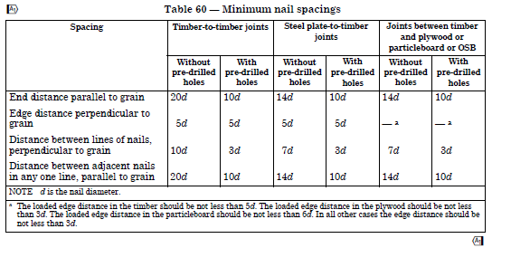
No you also need something at the bottom to stop rafter uplift. The birds mouth needs to be held in close contact with the wall head / lintel. You could maybe use a truss clip but on the outside face of the lintels. Will be nicely hidden here, but you need to fix them before the sarking / tiles. If you want to go for a "sturdy" job use the 7090's all over.. but some of the nails will be to close to the joint between the double lintels.. nail edge distance. You best bet is to assemble is and do a trial fit with the 7090 brackets.. use common sense.. do they look right if not try a truss clip. Generally a truss clip has 6 nails into the lintel / head binder and 6 into the rafters all with at least 19 mm edge distance for the nail in the loaded direction of the force if using a 3.75mm diameter nail... 5* 3.75 = 18.75mm ish.. Now that is quite hard to get right on site when you have angled timbers resting on a say a head binder. Have copied a table from BS 5268 for reference. But if you fit say truss clips on the outside the problem often "goes away"
-
Thanks Andy.. given me food for thought.. every day is a school day.
-
You are quite right. I expand. Firstly an appology.. My choice of wording lacks substance not least. With hind sight the use of the word "flair" .. wrong word to use as it sounds demeaning.. that was not my intent, far from it. Yes I do. But some jobs.. say knocking down an internal wall to create an open plan space are very much my bag.. SE.. not an Architect's as I have enough experience to deliver good design right the way through to completion.. I wear two hats and I have studied hard to be able to do so.. yes Architecturally.. the lines get blurred here.. but if you want to argue the toss I would say I'm just as well qualified to do that type of job as you as it is about the project holistically? Look at the other side of the coin.. you have loads of experience as an Architect.. I bet you can design a house / structure that will stand up structurally and be safe.. you just need an SE to "stamp" the paper work. I work with Architect's who I would quite happily trust to design my house with no input from me if I was say unwell. The two professions cross fertilise.. why can't an Architect use judgement to design a safe structure? For thousands of years they have done pretty well at it without SE's @ETC I'm fortunate to be able to work with Architects who are very talented, some are ageging but they are the best folk to work with as we just gell and focus on design rather than having a pissing up the wall competition.. about our titles.. that is good for the Client and we all like to work together.. the Client picks up on this and feels they have a team that is genuine... and that is partly why I'm booked up with work well into next year. For all.. Architects ..one of the reasons is that it takes a minimum of seven years study and hard work plus a lot of luck to even be considered for your Architect's chartership. Architects don't just draw stuff and wear sheepskin coats (although they are.. these coats as my wife tells me are coming back into fashion.. hang on to that coat ETC.. my fatherinlaw has one.. have my eye on it! ) they also know about contract law.. have a deep knowledge of the building, planning, fire regs, legal expertise.. land boundaries and a whole load of other stuff... long list. @ETC I'm definitley not knocking Architects, As an SE there is mutual respect so again apologise. There are indeed bad Architects, but some truly awful SE's who just don't communicate with their Clients in an reasonable way and just get stuff wrong. To finish. Rather than use the word "flaire" what about "art".. Our SE profession is often described as an art and science of design.. Architecture is the same just more emphasis on the art? There is no doubt that an Architect can bring something to the table that others do not have... be that design skills.. innovation, sage advice.. and in the round they may save you money, design you a house that you love, can sell on and make a profit.. For all and for me you need to find the designer that suits you and that requires a bit of leg work.
-
Learning to render external walls
Gus Potter replied to OllyIB's topic in Landscaping, Decking & Patios
Hey that looks ok.. seen a lot worse.. looks like you have something to work with here. Firstly the perpendicular joints at the bottom.. are they open and do you know how the wall is drained at the back? You'll get loads of folk chipping in on BH.. the more photos you post the more info / suggestions you'll get. The length of the wall looks ok in terms of retaining the soil as it has some good returns to brace it. If you want to finish it yourself I would start with the steps. What do you want to put on top? Could be slabs or at the high end a porcelain tile? Next is the risers to the steps.. how do you want to finish that? Then the copes at the side of the steps any thoughts? Is BC involved? Do you need a hand rail as the change in level is more than 600mm? Once you have nutted that out then turn to the render... that is the last bit. Any copes need a good drip so they need to be at least 40mm wider than the wall on each side.. after any render. I'm sure @nod will pitch up with the best solution. Main thing here is to sort the drainage behind the wall so you don't get frost blowing off the render. Once you have nutted out this then yes you could render it yourself.. but it takes a bit of practice so it may be that when you look at all the other bits it's worth getting someone else in to make it all a top job.. the money lies in finishing the steps and the copes / maybe hand rail. I think that is where you could learn to do it yourself and save the money.. one step at a time.. where as rendering.. you only get one go! -
Interesting question.. Gut feeling is you need to study the regs in detail.. and also refer to BS 7671 .. IEE the wiring regs and the safety regulations. Personally I would avoid it like the plague.. as soon as the power goes off you'll need to reset them all and BC I think will have something to say about that. I get the home automation thing but remember you may wan't to sell your house later to someone that is less tech savvy.
-
Learning to render external walls
Gus Potter replied to OllyIB's topic in Landscaping, Decking & Patios
Post some photos and you'll get a lot of help / guidance / suggestions. -
Advice re Chapel new build
Gus Potter replied to lakelandfolk's topic in General Alternative Energy Issues
Pile in folks, lots of folk on BH will be happy to help. To get the best out of this then it all starts in the ground and you work your way up from there. If you can post more info then will be happy to chip in with what I know as I'm sure others will. -
You have hit the nail on the head there. If you are an SE you are responsible for folks lives.. if some goes badly wrong you could kill a lot of folk. @saveasteading If you are a Civil Engineer and your dam fails falls down you could kill thousands. Yes you carry responsibility.. and it can keep you awake at night to say the least. That said there are a lot of checks and balances. The very first thing you do is to ask yourself "does it look right" if not it is probably wrong.. that takes experience. If you are on BH and asking a question as it may not look right to you.. then on balance you are probably right.. I encourage everyone to ask. Sometimes the question from the "lay person" is vital as professionals can get locked into a way of thinking and.. subject to "commercial pressure".. That simple question could save the day! That is part of the checking and balancing process. There are many more so if you have a good design team (that includes you) there is no reason to loose sleep. So to all on BH.. keep asking questions!
-
My own view is that much depends on experience, knowledge and demonstrable skill. I have worked with some SE's that I would not let within a country mile of my own house! I work with an Architect that has been at it for 50 years.. he designs stuff and I say to him why do you need me? .. he says.. for the SE paper work young lad! Then you have all ground in between. I think the secret it to work out what you need and find someone that can do what you want and have experience to say.. hang on.. here is a bit of friendly advise, I'm invested in your project.. let's not drop a clanger.
-
Hi Mortar. Have not checked you figures as kind of off duty here. These brackets look like a Simpson AE35. You have to wrap the top tab over. Your train of thought is good. You mention wind.. probably won't govern unless it gets close to a mansard type roof which you don't have. It's the practical side of things.. on a loggia folk will pile stuff up and use the posts to hold it all still.. that is where the risky horizontal loading comes from. I would stick to the 7090 brackets. Other way it to use ceiling ties.. but that compromises the vaulting effect to some extent. As an aside for all on BH. If you have an add on to the house with one side open and the rest clad you can encounter quite a lot of horizontal wind forces. This is what we call an open sided building.. has a dominant opening. You find this with hay sheds. In the spring you have the columns, it is just empty (hopefully) and the wind blows though. But say mid winter.. the bales are left at the sides and taken from the middle.. the wind blows in and can't get out the sides so it lifts the roof off for example.
-
Top response from @George Agree. Will do no harm to ask. To provide a bit of background. I started out as a building contractor, got interested in structural design so went to uni at forty to study structural engineering. Served my time training and now work as a sole pratitioner as a Structural Engineer and architectural designer. To be a good designer you need to have experience and a flavour of holistic desgn. I make a living doing what I do. Designing extensions, attic conversions, barn conversion, some steel buildings, some industrial, the odd new build, bit of ground works, garden buildings.. long list... it's a fun job but with responsibility... no free lunch. Now I think I do a good job.. but I do get some jobs that require the flair that only an Architect can bring. When this occurs I call up my Architect pals and say.. this job needs YOU do you want to collaborate? It is the sensible thing to do for me. I'm not a bad arctitectural designer but I know my limits. I know from years of experience when to call for help.. swallow your pride and this delivers a good project.. you learn from it and this makes you a better designer. That said I make my living wearing the two hats.. it is a competetive business this building malarky! In terms of insurance. From talking to my Architect pals I carry a lot more PI insurance cover under my SE policy than they do... in fact significantly more and as @George says I'm quite happy to provide the documents if asked. But.. I don't make a point of it when touting for business.. after all you are saying to your Client.. hey if I cock it up I'm well insured.. the point is you DON'T cock it up! My SE cover also covers me to do the architectural design and spout my thoughts on BH. In summary though for all on BH. The best thing you can do is research. Some folk on BH have loads of experience, know what they want and just want someone to produce the paperwork to get BC approval and check it won't fall down. Others are just starting out and maybe need someone who can guide them.. hold their hand while they cut their teeth on their first project. Yes it is ok to use an architectural designer @TryCbut make sure you do your due dilligance.. take references from past Clients and so on. Try and find someone local to you that can nip round once the project is underway and check on the builder. The main thing it to find the person that suits you and you gell with. Then explore what they know and what they can do for you. If you have put in a bit of ground work you'll soon know if they are up to the job or not. All the best with the project.
-
Steel to support a garage door
Gus Potter replied to puntloos's topic in New House & Self Build Design
Hang on! I may be over thinking but my first reaction is.. the 203 UC columns and beam are probably working to provide part of the horizontal stability stystem to the house. Easily over looked but critical for safety. Can you post more of your plans. Also post if you can the connection design between the column and beam as this will give a clue as to what the columns and beams are intended to do. Please don't swap these out until you check with your SE. -
Stud wall spacing options & ply faced studs?
Gus Potter replied to ruggers's topic in General Joinery
Unfortunately it often partly ends up that way, a non load bearing racking wall can catch you out. Advise you stick with your SE's specification. In written form you have a timber frame panel that carries no vertical load but it needs to stop things moving sideways. Say the top of the panel is loaded horizontally. This horizontal force gets transferred to say the floor below that resists the horizontal force. Now you have two forces acting in equal an opposite directions but they are separated vertically. This introduces an overturning effect into the panel. We call this a complimentary shear force. The static laws of physics say that for a body to remain still every force has to have an equal an opposite force. Thus even though your panel is not carrying a vertical load.. only a wind load the vertical fixings at on side will be subject to uplift and at the other side a downwards force. That is why you may wonder why your SE has come up with what may seem an onerous spec.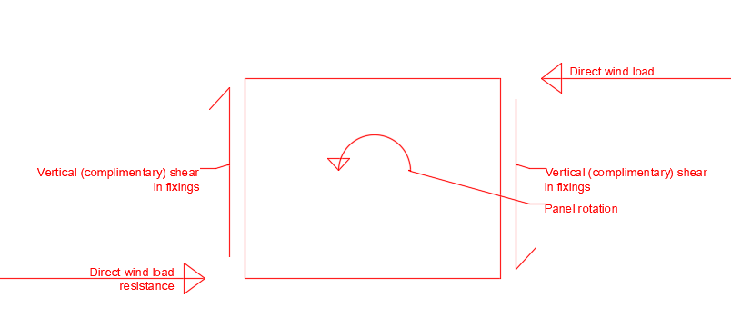
-
Look at this another way maybe. If you can afford or even contemplate building a 500 sq m house then you can afford to talk to an SE that knows a bit about design and costs. I'm at the other end of the country but wear two hats, SE but also a designer hat and have Clients coming to me that want to build big stuff. We maybe spend half a day chewing the fat and then I say hey I think this will fly but if you want high end then I know Architects that will make it work. The big thing is that you get a different viewpoint and a down to earth one! Post more and you'll get loads og help and advise on BH.
-
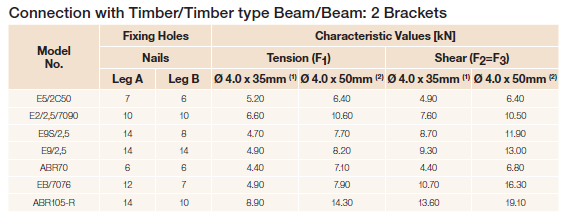
Peter. To you and all the mods. Big thanks from me and thank you for all the time you put into BH to make it work. I'm not a legal eagle, I know bit but probably enough to be dangerous! I think you have our back on Build Hub but even if you don't then.. to make a forum like this work you need all sorts. I chip in as it's a friendly site, have got to meet some folk in person and made new friends. Not bad eh? I learn loads of stuff here not just from the pro's but also from the new members that are coming on the site with innovative ideas, asking questions.. challenging the norm. Without new members and you old sorts (not me as I'm only 58) doing your tenth self build the site would not have the richness that it has. If you doubt then have a look at the Farming Forum.. yes it is commercial.. not my cup of tea but they have the depth and breadth of contributers that makes it work. BH is the same without the commercial and that "edge" you get on commercial sites. In terms of liability. When I was training and cutting my teath one of my mentors said (runs a top notch SE Consultancy) .. Gus you are worried about getting sued too much.. Clients don't want your caveats.. they want answers and good commercial ones too. Study hard (we are giving you the tools to educate yourself @SteamyTea) and you will be able to give the right answers / solutions.. ! If you do then you won't be sued.. well you might by some dafty but folk are folk, that is the price you pay for having an exiting job. Enjoy your job, do what you are good at and have fun. So in that context lets look at Ok lets go back to my earlier post. Say the rafters are spaced at 600mm centres. Thus the shear load at the top end of each rafter is 1.64 * 0.6 (spacing) = 0.98 kN. Below is an extract from the Simpson brochure for the 7090 brackets. I have not copied it all but the bracket capacity changes depending the grade of timber and nails you use so please check this yourself. The main thing to take away from this is how you read the table. This table is based on Eurocode design and the value we are interested in is the characteristic value. In the previous post I showed how we worked out the DESIGN loads.. we worked out the loads and then applied safety factors. BUT we also need to apply safety factors to the Characteristic loads for resistance as we are using limit state codes.. which in this case is the brackets. Generally for simple timber design we apply a material factor of safety of 1.3. Thus you can see for the 7090 bracket the characteristic shear load with 35mm nails is 7.6 kN. We divide 7.6 / 1.3 = 5.84 kN which is well above the 0.98 kN. Caution.. read the fine print as the values are based on two brackets.. one each side! Now that seems overkill in terms of holding the roof up.. but What you do here is pile up logs and inevitably they will end up pushing the vertical columns (timber posts) outwards. The 7090 bracket also work in tension that have a declared value. The brackets can take tension where as joist hangers commonly can't. Earlier we looked at the resin fixings.. these to can take a bit of tension.. For all if you are trying to get you head round this sort of thing try and work out what forces you have and follow where they go. Will have a go at this but not tonight as screws into the end grain of timber are not.. "that good".. I would try and avoid any end grain screw that is subject to a tensile force.
-
Too right! Great options from George. Spot on, must have been some spare capacity in the design. All the best with the project.
-
Give me a bit of time and I'll post something.. need to finish something on the day job first. Yes they are not pleasing to the eye right enough.
-
Can't see that well from your drawing but here is how you can do a qualitative / initial comparison to see what other size of beam might work. I'll use the values out of the Blue book as it's easy, just watch out as I'm using the Eurocode version as the beam axis notation is different between the Eurocodes and the British Standard. https://www.steelforlifebluebook.co.uk/ub/ First thing we look at in this case is how "bendy" the beam is.. how much it will deflect. The amount of delfection is proportional to the beam stiffness about the axis it is being bent. We go to the section properties part and look up the second moment of area about the y-y axis for a 254x102x25 UB which gives us a value of 3410cm4 Could we use a 203 x 133 x 30kg UB.. it does not have a larger second moment of area (only 2900cm4) .. we could check it but we are wanting to know quickly what could work. Lets look at a Universal column section and pick one that we can probably get off the shelf. https://www.steelforlifebluebook.co.uk/uc/ec3-ukna/section-properties-dimensions-properties/ A 203 x 203 x 46 kg UC has a second moment of area of 4570cm4 .. yes that will be plenty stiff enough. But it is nearly twice the weight but it could well get rid of the downstand. ------------------------- Next we check for strength. We don't want the beam to fail by the steel yielding. Moment capacity of a 254x102x25 UB = 109 kNm Moment capacity of a 203 x 203 x 46 UC = 176 kNm yes the UC certainly looks strong enough. Now if we can live with the extra weight of steel we can go to the SE who will check loads of other things; the buckling strength not least, which could less depending on how the joists are to be supported, and make sure it can be properly supported and so on. You also have a larger distance from the edge of the flange to the web so you need to check again how the floor joists and so on are connected. We could explore further. Would a 203 x 133 x 30 UB beam work if we welded some flange plates to it.. maybe but the cost of the plates and welding could well outweigh the extra weight of the UC section. Could we use a couple of back to back channel sections.. maybe but channel sections are more expensive and you need to bolt them together. Hope this helps but ask your SE and check what fire protection you need to the steel and how this is to be achieved. Sometimes a downstand in the ceiling can work well in big open plan areas as it provides demarcation between different "zones" you may want to create while still having the open plan effect.
-
Call it a clarification, any discussion, different view point is always helpful and healthy. I agree with you that you could end up using excess resin. But to keep say BC and the SE's happy best to follow the manufacture's installation instructions to the letter where possible, unless you know a lot about fixings and their design. Hilti and Fischer both make mention of nominal drill hole size for their threaded rod applications in solid brick. For an M10 rod nominal drill hole size is 12mm and for an M12 nominal drill hole size is 14mm and so on up to and M16 which needs a nominal drill hole size of 18mm. You can also (with careful checking) install rods into bricks that have voids. Here you get a sieve sleeve that goes in the hole first. You need quite a lot more resin for this as you need to flood the sleeve andsome of that disappears into the voids.
-
Don't think we talked about birds mouths? They are great but you need to tie back the posts and roof so they don't move horizontally. You can either use the rafters or the ceiling ties to do this. You can tie the posts back to the wall using the ceiling ties. But rather than using hangers for the ceiling tie you would use say Simpson ABR 9020 brackets. But this give a very much an "exposed look" often not pleasing to the eye. Have not got time tonight but will try and post a detail on how you make it all work while pleasing to the eye over the weekend. Still.. well done you. The nominal fixing diameter is M12 so you need practically a 14mm diamter drill hole and blow / brush it out clean for the resin. You could do hit and miss but much depends on how you want it to look.
-
You make a good point here and the advice you give is sound. To expand a bit on my own personal approach. When I joined BH one of the thoughts I had was.. do I use my own name or not. I concluded that if you mean what you say then why not use your own name? I run a business with a website (it's not slick as I wrote it myself and it needs updating but have plenty work) and sell my wares using my own name. Why not just use my own name BH? I can see where you are coming from. If you are writing on any public forum or even giving free advice to members of the public then potentially you can be liable for it. I'm an SE so carry insurance. Part of my policy covers me to give advice even if not paid for. That allows me to go into detail that others may not be able to do in public. That said if you look at my posts you'll see that I often introduce a caveat. Above I used the words "outline advice" .. you would have to be pretty determined to raise an action against me. In the round though I would hope that in the first instance if someone on BH felt that I was wrong they would invite me to explain or just say.. Gus.. your numbers etc don't add up and give me an opportunity to correct the record. We all make mistakes from time to time.
-
Think you might be pushing at an open door here. Get a grouting quote but when you do make sure you ask that the grouting company include for at least a 25 year warranty, full site remediation and with any luck you may have a couple of trees with protection orders on them. Basically get the highest quote you can with the full bells and whistles.. your SE will help you craft the brief. Then say to insurance company.. hey lets work together and we can both save some money.. if you go along with it you'll get no grief from us.. just we may need an interim payment or two. Can your Dad move into a nice rented pad or go on a cruise off the money. Knock it down and rebuild with the support of your SE. The ash is an interesting one.. if it has a high sulphate content then it moves about and attacks the concrete.. sulphate damage.. grouting won't help.. you often need to get rid of it if under the founds and that is not easy especially if the building is bearing on it. Also you need ask if what is the neighbours founded on etc.. do they have or will they have in the future a similar problem. Ask insurers, will they cover for next door compromising our works or if we do work will we do something that will lead to problems next door? Who is going to pick up the tab if we cause a problem next door while doing the work? In the round it seems like your Dad could end up with a new cracking house (and quicker too) and the insurer could save money? The hard part will be getting this point over to them.
-
Wow! You have put a lot of thinking into this.. Bit late here but will try and answer some of your points. I'll put my "BC /checking Engineer's" hat on to be pedantic.. the following is a bit of an outline on how I may do it and some of the things I look for. Well done on picking up on the snow and access load. You also have a snow drift load and "snow dumping coming off the higher roof, but due to the pitch and size of canopy that can be effectively ignored especially as it is what we call and "accidental" snow load case. You do also have wind load but on something this size it I think this can be neglected as you have good heavy tiles mitigating roof uplift. If this was a big commercial building, lightweight roof covering with the roof sitting just below the window cills I would check it to make sure it does not lift the cills.. could be embarrasing! Oh.. please excuse any typos. Have repeated your calcs in a slightly different way but made an allowance for the rafter self weight just to let you see how I may do it. I use kg as it's pretty close to kN that we use as normally units. Your tiles look pretty heavy, normal Marley concrete tiles are about 50 kg/ m ^2.. you must be using some nice clay ones, jealous here.. like a nice tile. I'm going to use Eurocode Design here as later this is compatible with the fixings then jump back to using the permissible stress codes of BS 5268.. as it's easier. I'll explain as I go along. Tile load on slope = 77 kg/ m^2.. for all this is the declared weight by the manufacture of the tiles.. it varies depending on how much head lap and that changes depending on the weather exposure and roof pitch.. who said life was a breeze? On plan load for @MortarThePoint= 77 / cos(46) = 110 kg/m^2 on plan. Add 10% for timber rafters, sarking etc. 1.1 * 110 = 121 kg... this is the "Permenant" load, using the BS codes this is called the Dead load. Now we have a roof access load. In both codes this is ~60 kg / m^2 for domestic applications but this is a load that is applied on plan. A slope load is the load running up the rafter.. like tiles. A plan load is more easily understood if you think about snow falling straight down or a few folk standing on a stair or a roof. You can only fit so many folk standing vertically and only so much snow can lie on a roof. This 60 kg/m^2 is the imposed load. Now we have two figures for the plan load. Permenant load = 110 kg.. lets convert now to kN roughly divide by 10 thus 10 / 10 = 1.1 kN Imposed load = 60 kg/m^2 lets convert now to kN roughly divide by 10 thus 60 / 10 = 0.6 kN Now we apply safety factors to these loads, the different kinds of loads get different safety factors. Using the simplistic Eurocode formula safety factors are 1.35 (Permenant loads) and 1.5 ( Imposed loads) the calculation follows. 1.35 * 1.1 + 1.5 *0.6 = 2.39 kN/m^2 on plan. Now as above take the effective span on plan of the rafter as being 1.375m (conservative) and as the rafter is simply supported at the ends the loads at the supports are calculated as follows: 2.39 * 1.375 / 2 = 1.64 kN/m. In other words the "DESIGN" load on the ledger is 1.64 kN per metre run of the ledger. The design load at the bottom of the rafter is the same neglecting the slight overhang. If you were checking this you would check the rafters, the hangers before checking the ledger. Just like you follow the money you follow the loads and check each bit as you go. That is really pedantic. To make it fly take the rafter span on slope in feet divide by two m and add one inch.. that will probably be fine as it is a canopy. Thus 2.4m = about 8 feet.. 8 / 2 = 4 + 1 = 5 inches. I would adopt a 120 x 45 C16 rafter @ 600 centres max for the rafters. Standard Simpson joist hangers will do fine at the top end of the rafter.. can show they will work but it will take all night to finish this post if I do. ----------------------------------------- Lets now look at the capacity of the fixings and work out how many we need. If you follow the method I have used above to calculate the loading. I start with the loads (characteristic loads) and apply safety factors to get the design load. We now check to make sure that the DESIGN load is less the design RESISTANCE. Not normally a shouty bloke (use of capitals) but for all it is really important so please forgive. Things like masonry fixings are very tempremental not least as we are often fixing into masonry that is variable.. brickies can have off days and so on. In the table that @MortarThePointhas uploaded you can see two columns. One characteristic and one design. Take the M12 fixing.. the number we are looking for is the design resistance of 1.62 kN in shear. Now here it can get really complicated as we are using the Eurocodes. You'll see there is also a figure for the approved resistance. This is the value that you would use if you did not use the safety factors on the loading calculation... permissible stress design codes. Lastly always take note of spacing and edge distances. Lets now work out how many fixings we need per metre based on an M12 bolt and see if we can practically install these. Design load is 1.64 kN/m. Design resistance is 1.62 kN per fixing. Suddenly you can see the loads are pretty small and that you only need one roughly one fixing per metre run of ledger. To be exact we would need: 1.62 / 1.64 = one fixing per 987 mm which is a funny number to deal with on site. Practically I would say one M12 fixing per rafter bay if they are at 600 centres. Now all looks great above but lots of BH folk start using the same idea for 3 - 4 m spanning floors and ledgers for trussed rafters.. you can quickly see how these fixing will stop working! --------------------- The ceiling tie serves to restrain the top of the posts. Just use the same fixings and spacing as the rafter ledger.. line them up so they look good. 70 x 45 C16 may be what you want.. if hanging plant pots / growing a vine of something go for 95 x 45 C16 / maybe C24 as it has generally less knows and looks less cheep. You coaul calculate the wind load in the roof but using the same fixing as for the ledger will be fine. ---------------------- The transfer beam along the top of the posts. Have run out of gas here a bit and it takes a bit of explanation.. you use the design loads to check the strength and the unfactored loads to check the deflection. With timber you need to calculate both the bending and hear deflection.. bit more work. Suffice to say that on that roof you could I think show that a 200 x 45 C24 timber would work or two 170 x 45 C16's. The single timber may look a bit "weedy" and not sturdy to the eye.. it's also about it looking balanced and visually pleasing. ----------- A 100 x 100 post around 2.4 m long will take a lot of vertical load, again can show another day how you check it. ------------- Simpson post bases.. they are good, last a while, just a little more expensive. -------------

-
That crack looks like something that has got a grip of the edge of the floor and stopped it from moving at the cover plate between the tiles and the concrete.. The rest, if isolated, are probably hard to argue about. Before you chuck in the towel is there anything on the outside of the building that corresponds with the crack in the floor? Also have you checked the floor for level? Another thing it could be is that if these are door standards (can't quite tell from the photo) they are often fitted later on top of the concrete.. then they may have swelled and be bearing down on the floor slab at its weak spot. Check to see if they are in contact with the concrete at the bottom. The joiner may have tightly sprung the standards into place.. that coupled with a bit of swelling could be another cause. The shape of the crack (an arc) suggests that something might be loading the concrete at the edges of the opening?


