Gus Potter
-
Posts
2340 -
Joined
-
Last visited
-
Days Won
29
Everything posted by Gus Potter
-
Well done you for giving this a go.. If you want I can give you a few pointers on what you need to do to get the preliminary sizes for you timber frame (TF) and the grades of timber you may need. To do that I would need to know.. A: The floor plan dimensions, location of the internal load bearing walls roof pitch and need to know about any funny loads you are introducing.. pool tables ect.. B: The ground, first and second floor levels. C :The sizes of the openings.. windows and doors. D : Your post code so I can assess the wind and snow loading. I'm minded to give this a go with my SE hat on as.. 1/ You have made a good effort. 2/ It may help other folk on BH understand what goes into the preliminary sizing of a timber frame.
-
Using muck away to level a paddock
Gus Potter replied to WannabeBob's topic in Landscaping, Decking & Patios
My pragmatic view. Your starting point is to spend a bit of money investigating the ground up front and in particular the behaviour of the ground water if considering a basement This is where the cost uncertainty lies and the big risk. If you don't do this now you'll spend countless wasted hours trying to figure out the superstructure design.. and then you may have to revisit all of that once you learn later about the ground. Now that and the following may seem a bit of a lecture but if you go to a TF company / basement company for example with limited information they will suss that out and inflate the price to cover the added risk / uncertainty. There are basically two rates.. if you have a Client that has not got a clue.. there is a risk there.. so you add more to the price. A well informed Client with good drawings and a bit of professional backup.. you charge less as the risk is reduced.. in the round you end up making the same profit as a Contractor. How? well... if there are extras the professional team often play fair with you so you get a fair days work for a fair days pay. Mind you if you a Contractor who does not recognise fair play.. then the gloves come off. To give you a ball park figure. You could get this kind of preliminary advice for about £1500.00. But once you get chatting to the person who is giving the advice they will tell you loads of other stuff, point out the pitfalls and engage with you... after a couple of conversations you'll probably realise that you have got value for money. For me all I need to do to wash my face is to save you one weeks labour on site for two operatives. The sum is a bit like this this.. 1 x a skilled operative at 8 hours per day @ £250.00 per day for a week = 5 x 250 = £1250 A labourer at £120 per day x 5 = £600.00 £1250 + 600 = £1850.00 > my £1500.00 Now that is my rough sum.. but I know I can easily save folk that. It's just that folk don't believe it until they find out later that they maybe went about it the wrong way. I know some BH folk are a hostile towards Architect's but @ETC is one and very experienced... just speculate.. how much someone like that could save you but still achieve the same in terms of Architectural design if you get them into the fold for the whole project! Now imagine if you got both the SE, Architect and you all on the team early on.. The savings can be massive.. In some ways the professionals self regulate for the benefit of the project if they are committed. There are some folk on BH that don't need this level of support, some are essentially highly experienced developers with a professional construction background. But most folk on BH are not like that.. I'm trying to look at it in the round. I did a self build many years ago and certainly did not know what I know now.. also at that time there was no internet and no Buildhub where you could go for advice.. I made mistakes / lost money based on what I know now. In summary get an impartial professional in early who can guide and give you the information you need to make an informed decision, you still have control over the process. -
Read the attached first.. once you get a handle on the basics you may find the solution is staring you in the face. If this guide is not enough then you'll be much more informed when you call the lead association, they will appreciate that and will tend to recognise that you have made an effort yourself to solve the problem on your own... but just got stuck. Calder guide to leadwork -GTGLW-210213(5).pdf
-
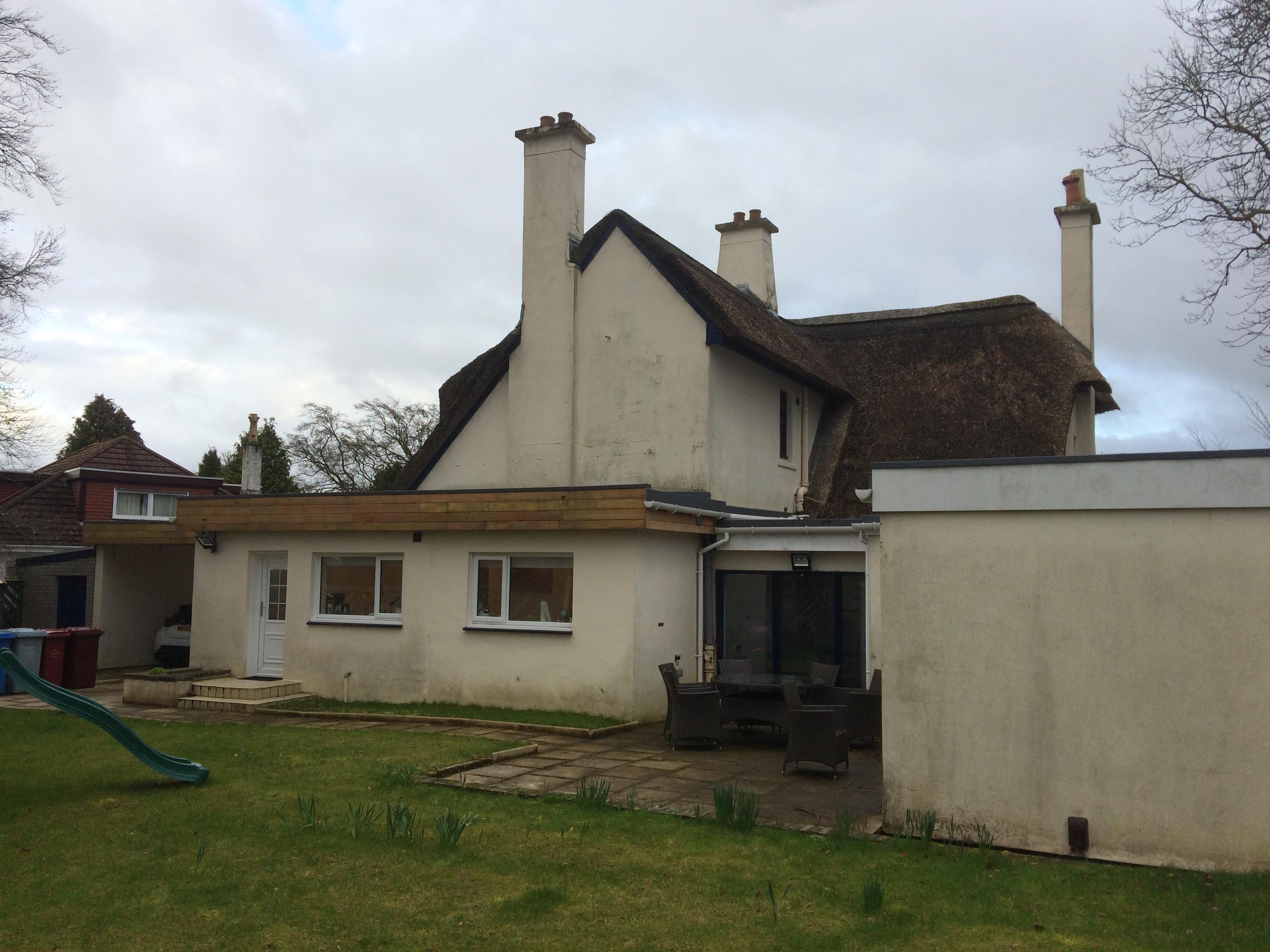
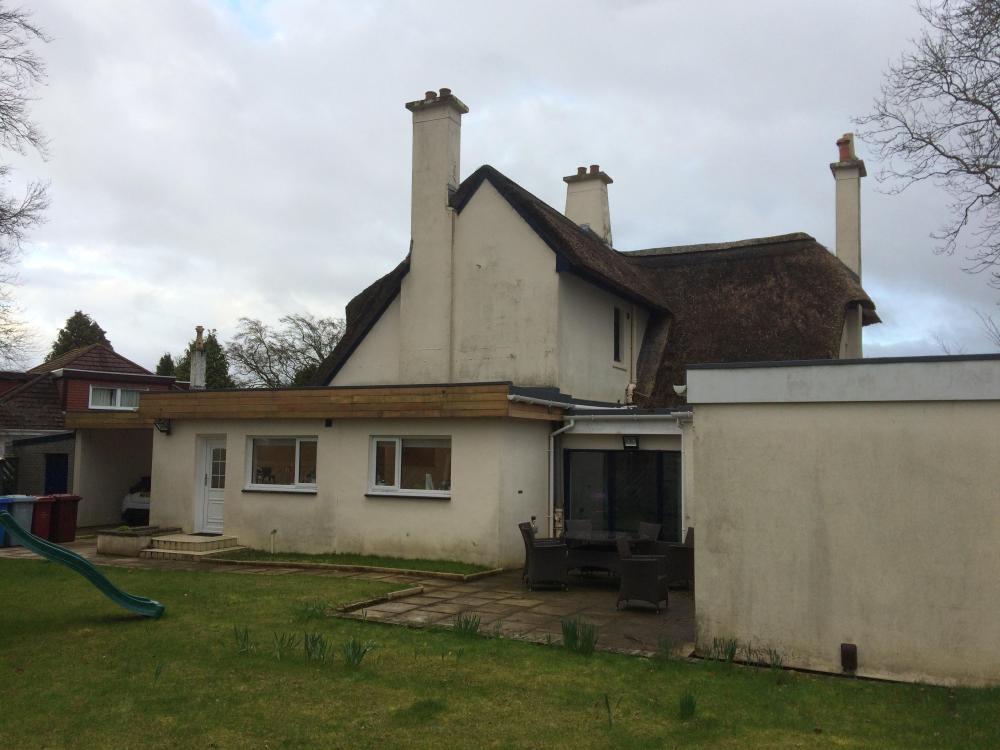
Here is a puzzle. I'm doing an upgrade job on a listed thatched house in Scotland.. there are only about 200 of them left that are meaningfull in Scotland. To cut a long story short the thatch was relaid completely in about 1950 - 1953 by a new town development corporation.. think Milton Keynes. In their wisdom they thought it would be a good idea to guard against fire. To that end they overlaid the rafters with asbestos cement sheets and thatched on top of that. Now I truck up and want to knock a lot of the ground floor walls out to make it open plan. But to do that I need to support some big point loads from chimneys etc. That means I need to tie the structure back into the top part of the roof. But the Client wants to add insulation on the first floor above the ceiling chords, near the shoulders of the chimney breast you can see below. I'm thinking.. hey Gus leave that alone as I could make things even worse! If I insulate the ceiling in the upper floor I'll shift the dew point in even further and could end up with a compost heap on the roof. Any thoughts folks? I'm appealing as there may be BH folk that can give a bit of advice.. am I being too cautious? The climate up near Glasgow is not condusive for thatch in general. I can't show you the front of the building as it would make it identifiable, the front looks great, Crittal windows etc. The chimney is one of the point loads and there is not a lot to stop it falling into the garden. My steel design and temporary propping involves pre bending (pre loading) the steels to make sure nothing moves.. post for another day on how you do that with off the shelf DIY stuff. Mind you if I get this wrong you'll read about it in the papers as it's right in the town centre.
-
Look forward to your performance report in a few years. Keep us updated on that one.
-
Lead at times is not that forgiving. The more you try and fix it.. the more of a hole you can dig for yourself. Don't use heat as you'll need a lot and could set light to the roof. Would foam fillers work for you! It's probably the wind driven rain / snow your worried about as your roof seems to be a pretty low pitch? Set the fillers back 25mm back from the end of the tile on dry day and wet the tiles with a hose, then see how far the water gets up. Once you have got the set back right then run a bead of silicon under the bottom of the fillers, not top and bottom. Try that as its a reversible process.. where as trying to reform the lead is not a it becomes work hardened. Have a look at the below and see if that might work for you. https://www.roofingsuperstore.co.uk/product/lightweight-tile-eaves-foam-fillers-pair.html
-
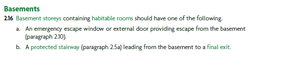
You've opened a can of worms here! The Scottish regs are a little different but here is another part of the English regs: This is where it gets complicated by the need for open plan living. Let's say you have a stair leading up from a single storey basement onto the ground floor (GF) area that has a kitchen / open plan area, then another stair leading up to attic rooms. Now you can't make a protected corridor as you have that open plan GF. I agree with you all but just digging into this in my own way. Lets go back to basics. If a fire starts somewhere you need to get from the apartment you are in (usually a bedroom or principle living space, bathrooms are excluded as you should not be in them that long! as are other parts where you may not be spending a lot of time in.. balances occupancy rate with time spent = risk to a place of safety (outside normally for a house) without having to essentially go though another room then a corridor to exit the building. Now if you have an open plan kitchen on the GF that is a big fire risk.. you could get easily get disorientated and trapped in the basement. Remember, few folk have been in a fire and when panic sets in folk can behave in odd ways. In terms of saving lives. It's the smoke that kills most folk. I've not yet delved too deep into the English regs yet but in Scotland the regs have recognised that lots of developers want an open plan space on the ground floor. To get round this we are using sprinkler systems (the ones that don't need a big storage tank) and often what we call enhanced grade D fire protection. I don't think the English regs are requiring sprinklers yet. An enhanced grade D system often means we put smoke / heat detectors everywhere and get it serviced by a professional, that includes the consumer unit cupboard.. anywhere a fire could possible start and interlink them all. The idea is to detect smoke as soon as possible, then heat... as by the time there is heat there tends to be a lot of killing smoke. Now if you are intending to use your basement as a plant room only then the regs get relaxed I think. As I said I've not checked that part of the English regs yet. But to call it a plant room you can't go putting wall paper up and a bar with the full optics and 40 oz bottles of your choice etc! But pragmatically if you're going to be down there a lot I would want another way out if push comes to shove. Maybe a light well with an opening window that you could get out and clamber up to ground level.. you would have an element of encouragement especially if your pants were at risk of going fire! You could navigate the regs by keeping the basement as a plant room / storage space but still keep you safe. In this my guess is that you would need a fire door at basement level to protect the area above. In the round for me it's about creating a safe space for all your family and visitors. Yes comply with the regs.. but also apply common sense.
-
Correct. What about sitting on the fence. Plan your UF slab on the basis that you are going to polish it. Design it, cure it and turn the heating on. If you have made an error.. not achieved the correct quality control etc, lay a timber floor / carpet over to hide the cracks. If not cracking what about using a polished concrete overlay, yes I know it's not the real deal but who is really going to know? I was at a job where they used an overlay on a normal reinforced concrete wall, you could not tell the difference and in fact looked great cf some (a lot of) the rubbish concrete jobs you see. It's one of the few times I've see a concrete finish good enough that I would have in my own house. Below is a random link to overlays. https://nichepolishedconcrete.co.uk/overlays/
-
Mine is wtf! Look folks.. If you are educated then you state what the abbreviation means and bracket that, then use it later in the text. Using abbreviations is of no use to new folk coming on Buildhub.. they are keen to learn, also there are folk joining BH that have particular skills.. they may have abbreviations that we have not got a clue about! Imagine you are a someone trying to learn and look back on previous posts.. I try and make my posts simple and easy to understand as best I can.. sometimes I may come over as a bit odd / dafty.. but in my day job.. you'll find me a bit more concise!
- 55 replies
-
- 3
-

-
- acronym
- abbreviation
- (and 4 more)
-
CLS or general carcassing timber for studwork
Gus Potter replied to BadgerBadger's topic in General Joinery
Two things you need to watch out for.. If the wall is load bearing a standard British or EU section will be 95 mm deep, the equivalent CLS section depth 89mm and the widths are also different. CLS can be cheaper but the amount of wood you get is less.. you get what you pay for.. don't complain later if what you bought does not fulfill it's intended function. An 89 mm deep stud has about 12% less bending capacity than a 95 mm deep stud and I have not included the width reduction .. buttttt.. it's only a quarter of an inch>> who would have "thunk that? Ruskin the common law of business: "It's unwise to pay too much...but it's worse to pay too little. When you pay too much, you lose a little money - that is all. When you pay too little, you sometimes lose everything, because the thing you bought was incapable of doing the thing it was bought to do. -
Hi all.. It's always best to play off a straight bat. Often for the price a Client is willing to pay it is just not possible to show enough of all the detail on drawings or do the survey time. I get around this by including photgraphs on my planning drawings. Now I know that this is not the traditional approach but it stops a lot of folk getting in a bit of a " ...."
-
Take them outside, let them climb some small trees, get muddy, dunk them in cold water.. will save their lives later if they can handle that.. which most kids can do then your blinds will be safe.
-
Hiya, got a soft soft for you as you have done a great job and worked so hard. The builders may be trying to sting you at the end as they have other offers. Some times builders.. like lovers say.. it was good fun but.. I have a chance at hollywood and the big time. Post a photo of what you have. Also fesse up if there is an underlying problem, I think you're pragmatic.. is there more to this than meets the eye?
-
Wall mounted basic ASHP for workshop
Gus Potter replied to Mudmouse's topic in Air Source Heat Pumps (ASHP)
Suggestion: Imagine you are the installer.. done the training courses etc. The unit comes in a box and in that box tends to be an install template or a diagram as to how you fix it to the wall. Now you follow the diagram but you don't have time to actually think about how vibration / sound waves are transferred to the wall. Also, you probably won't have been taught about how sound can reverberate off things, or say a fence and excite vibration in say a soil pipe or transfer to a duct. If you think about a wind instrument.. say a saxophone, the reed which is pretty small converts your breath into a change in air pressure that gets amplified by the rest of the instrument. Now think about how a fan unit could be missing some flexible mounting washers, you have ducting that may be amplifying the sound.. sometimes it needs a bit of thought. In some cases it could be that you just need a bit of galve band to stop the vibration growth that we hear.. we call this damping. As SE's when we design floors we clearly don't want them to fall down. But we also want them not to get "excited by vibration" as this can be dangerous but also it make folk unhappy when they are walking over or in them. Often we just need to add a bit more weight.. same applies to ventilation ducts. I would look at the simple stupid first and see if you have covered all of that before blaming the unit. At the then of the day if the unit is faulty the manufacturer is just going to ask the same questions as I am. -
Hiya. I was looking at the photos and made some assumptions that the photo was realistic. Anyway @puntloos next time.. ! But for all. Don't put all your busy tiles in the shower enclosure.. design is about balance, scale and light in a bathrooom not least. @puntloos I suspect there is more to this.. have they just done a crap job. If so then tell us and we will give you the tools to get some money back. @nod I would be quite happy to pay you £250 - 300 a day plus your travelling time / accommodation / fuel and van so long as you worked at a steady pace all day. But at that rate I also want you to give me the benefit of your professional experience, if something is wrong then I would expect you to tell me before you start work and once it is complete I want it all in the tolerances and no mincing about from you if it is not.
-
True enough. It takes many years to become expert in you trade and in return you deserve the reward. For me I used to be a Contractor, and also a self taught trades person. I've installed a bathroom in my own house, striped everything back to the bare timber frame, insualted all that with a timber suspended floor. But I'm also an SE so know how all these materials interact. At the end of the day the materials / bath ect cost about 10k.. but to get someone else to achieve the same quality of work and not make an arse of it would have cost us 30 - 40k. We priced checked all of this, wife said Gus.. I trust you to make a better job and we can't afford that luxury otherwise. The biggies for me were fitting the chipboard on a timber suspended floor over my UF design ( but the UF for me is easy as I know what I'm doing), I glued and screwed that to death. Next was a decoupling matt.. not done that before but @nod etc gave me the confidence to tackle that. You need to take your time with this and use the right adhesives.. which are expensive.. but the tiles we have are expensive. The decoupling matt and extra adhesive added about 15% to the cost of the materials. Probaly one great tool was my glass suckers as I used them to lift and place the place the 1220 x 600 mm tiles. Also I used a tile levelling kit, worked ok for me. At the end of the day I'm glad it did it myself as I had spent the time taking advice. I'm nearly finished that room. I need to make a mockup shower screen to see how far the water spashes out.. it's not an enclosure.. just a bit of glass.. these things are bespoke but within our price range if we think smart.
-
This is a key concept I like to write some of my own spread sheets for this kind of stuff and really delve into the formulae that back up the industry software. By doing so it lets me manipulate to achieve the best design particularly, at concept design stage on old structures. @saveasteading has referenced in the past recognised research by say Historic Scotland and other accepted data that demonstrates that old stone walls are better insulators than we often assume at the outset. These old stone walls are not really solid, they have lots of air gaps / voids and have a significant insulating effect. Modern masonry walls have repeating joints and tend to be "thin" in comparison with old stone walls where the mortar joints are offset. OK I mention Scotland.. but what about the some of the early buildings in Bath e.g. that were all constructed in stone.. facing stone on the outside, rubble fill with random stone on the inside. This is good design. @ProDave has highlighted issues where if you don't seal the service void it can set up nasty convection currents / drafts that bypass the insulating effect. This is not that hard to do (seal the service void) in my mind if you are self building and want to do a bit of hands on stuff. If you do you'll end up with a great house for often less effort than you imagine. All you need to do is know when you have to say to the kit erector / etc.. hey this is the bit I want to do over the weekend before you sheet the inside of the walls. This is a critical point. BC will look at the job and may say.. this part is new work so it needs to comply with the latest regs. But the other parts of the work are an "upgrade" Depending on each authority you'll get a different answer. Your Architect needs to be right on top of this and should be able to explain how the the BC game is played and at the same time understanding and explaining to you how each design decision will impact on you if it is your forever home. Now if you are only paying your Architect a few quid.. then you'll get an off the shelf design. Pay them the right amount and a bit extra to phone friend (an SE who knows about this stuff) and you should at the end of the day save money in the round. Expect your Architect's fee to double for them to get right into this. Now this might sound a bit scary but if you double your payment then in return they should be able to cover that in practical savings in construction cost (if an experienced Architect / Designer) and more as you have given them time to really do all they are trained for.. you can set them free and at the same time give them responsibility for the overall design, detailing / detailed drawings (very important) and budget constraints. @ETC is that fair comment?
-
I have large format tiles, but installed them myself. They are tricky. I was particular as I wanted all the joints to line up with the tiles on the floor, took myself and wife ages to not get too heavy a pattern, just like you have noted. At the end of the day even though we had some technically 37 different configurations of tile pattern we had to make some compromises. But I think you may be ok.. remember the job is not finished yet! I can see a recess on the RHS of the photo and assume that is where the shower will go? Once you get all the screen, tray, soap dish fitted etc the wall should balance out as you are going to introduce "some busy stuff" on the RHS. What we didn't want to do in the shower area was to have too much density of pattern in the shower enclosure (makes it dark) as we know that once all the bits are fitted the shower area could appear to be a "black hole" without the "woke" you now get on Dr Who that of course brightens our life up considerably. Clear the room out and do a trial fit of all the stuff you are going to install in the bathroom and see if it makes any difference. report back.. I hope you have a nice surprise!
-
What a find! Nice approach as plenty others chipping in on the Architectural side. I'll limit mine to some SE stuff and some of the history of many of these types of Miner's cottages. I've done a few of these in the past.. here are some of the things I have learnt along the way. Mine owners built these houses at the lowest cost possible using the cheapest materials and labour cost.. just enough to keep their workers working. It's fascinating subject to research. I'll assume these are coal miner's cottages. Often a byproduct of coal mines is clay.. (they often had to dig through this to get to the coal) used to make bricks. the good bricks got sold, the "seconds" were used on the cottages. The good coal went to the big houses and for ships boilers, iron works etc, the low grade, full of sulpher coal was supplied to miners to keep the houses above freezing. High sulpher coal creates not least sulphiric acid which rots the mortar in the chimney's something awful. You have some cross walls but the mine owners didn't send their best masons to build the cottages, as they we often employed building the "manor", wool and jute mills ect. This means that the bonding of the cross walls is likely very poor. Also the external walls tend not to be that well bonded, the good stone went else where as did the best lime for mortar. My inclination is to look /ask.. on a fag packet what happens if we strip out all the internal walls on the original part and replace with thinner walls on a modern concrete slab with UFH. How much extra square feet are we going to generate? If that fag packet sum looks any way favourable then now we have a blank canvas to work with Architecturally.. a big open space. The new walls get tied back into retained external walls to provide any horizontal stability we need. How much easier / cheeper is it going to be to just cast a new insulated slab in a one go cf navigating round any internal walls? What savings can be realised by having a blank canvas in terms of abour / servicing and so on? It would be interesting to know how the existing walls really are constructed and what they are resting on. Until you know this you can't really make informed design decisions. Everything you do will hinge on this; the approach to insulating the external walls, you want to vault the ceilings?.. this will often introduce point loads.. you could end up wasting a load of cash if you don't get a handle on the existing construction in detail. Can you tell us more about what you know about the existing ~1800c construction and the later 1970's one, is it a cavity wall, how wide is the cavity and what are the walls made of. The good news is that hopefully the two storey bit will be heavy so that can be inspected for movement.. if it is sound then you have the makings of a benchmark.. you can say.. well that bit has been sitting there at two storeys for 50 years.. good indication of what the ground can carry sitting on this type of foundation.
-
Hiya. @gaz_moose and @ETC solutions can work well. Just depends on the type of detailing you want to do to finish off the roof. Cold flat roofs used to be common I (many worked fine) but now we stuff loads of insulation into and under them and BC etc.. and myself are not that keen on them for houses not least.. but.. Being pragmatic. It's not a kitchen, utility room or a bedroom where folk are sleeping in, thus the level of water gas generated should be relatively modest most of the time. Many of these older types of cold flat roofs relied on cross flow ventilation, usually via soffit vents. Most of these older types of flat roof are attached, say an extension which can inhibit the ventilation of a cold flat roof. A quick bit of rough theory, I have left out a lot but hope I give enough to let you understand the principles. To achieve cross flow ventilation on a flat roof you need to generate either / and or : 1/ A difference in air pressure between the windward and leeward side of the roof and / or have a sufficient slope in the roof to induce air convection currents. You get the best air pressure differential when the walls on the leeward and windward side (your roof joist / air gap span direction) are low and wide compared with the eaves height. This leads the wind to flow up and over the roof rather than round the sides of a structure. By promoting this type of wind flow you'll create the most favourable conditions to vent a flat roof. You have an advantage here as this is a stand alone building so avoid the problems typically associated with a cold flat roof extension. 2/ And / or induce air convection currents within the cold vented space we need heat.. that comes from the internal space in the winter. But that is lost heat which we are now keen to avoid. This goes some way towards explaining why cold flat roof were ok in the past but not now. I think this will work if you are careful, when partying.. leave a window open. Also avoid adding log stores and other paraphernalia / planting of trees etc that inhibits air flow round the building. Yes, you want to stop beasties getting in to the vent void as they will very quickly fill it up to make a lovely home for themselves. Mitigate by providing other habitats; bug hotels, bee habitats, bird boxes etc that you'll be able to see and enjoy. Don't know if you have frogs but you could do a bog garden from the rainwater run off and top that up with the garden hose if need be?
-
Hello there. What a delight to see your post. I can see you have out a lot of work into your post so thank you for that. My first question is can you show us some pictures of the views you have from the site. If you do then post and mark them so we know which way we are looking. Next would be.. do you know what other folk find cost effective in Latvia. Clay is clay but methods of construction are often driven by labour cost and available local materials. For example I think you have access to better quality timber than we do in the UK. Can you give us some tips on the things that are critical to your design? As a first glance your design seems like it needs a bit more work. But unless you can tell us more about where you live and so on I don't think you will get the best value out of Build Hub.
-
There you go.. plenty feedback for you to work with.. all the best.
-
I see this often. it's not unusual. Some folk really take the piss.. but some get away with it so you really need to watch out and be on your toes. The planners can and will drop the ball. You can't rely on them to protect you. Don't assume that the applicant's agent will be playing fair. On some planning applications I get paid to sail as close to the wind as possible. I always stick to the rules but if the opposition is less aware them hard luck to them. This is business. Think about it this way. The applicant maybe only pays a fee of £300.00.. what level of service do you expect from planning for that small some when they have many other things to do? It sounds like tough love, not trying to deflate you.. just trying to help. There is lots you can do. First thing to do would be to post a more detailed diagram with measurements. You'll get loads of help from folk on BH.
-
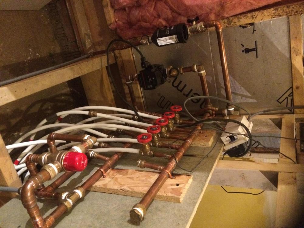
I'll chip in as the Philistine. I've said for years that all these complex controls on UF are a waste of time. They work fine for a few years, break down and then no one can fix then at a sensible cost. After while even the folk that have installed them.. yes even you BH folk then forget how they work and the nuances of your wiring up of the controls. I've designed a few UF systems in the past, always go for the simple stupid. Here is a knock up manifold made on my most recent house (photo is from 2020).. still working and have just extended it. It is a lot bigger now I have added more circuits and some basic controls. Now I know some may say you can't use gate valves.. I say they cost a couple of quid to replace if they start to weep. I know from experience that, as I did the same 20 years ago and times since, that this Flintstone stuff works, and folk can understand it. Lately I've added some extra electronic controls but these are not related to the pipework! Happy to take the pelters for my views.. ! You may think I'm bonkers but it was just something I know would work and made from fitting I had in my plumbing stock box. The biggy though is the blending valve. I have fitted an few of that type for other folk in the past and I know they are reliable. Also It's a 28mm blending valve so oversized to some repsects as it going onto 22mm pipework.. but my thinking is that any gunge will pass though it so I paid more for a bigger 28mm valve. My big mistake was to have some HIVE controls.. little did I know that I would have to keep updating the software and that if I move house I can't take them with me or some other shite like that. I learnt a lesson.. these are fundamental part of the house / structure.. DON'T trust them to third parties.. you could devalue your house a lot. Hi Marka. Before you start mucking about make sure your filters (nowadays mag filters) are clean and working ok. You probably have some kind of gunk / blockage coupled with those controls that we are all told will work for more than 5 years, the life of the system, like I stilll believe in Santa.. You don't want to shift the problem and say block your fancy heat exchanger on your boiler. Just before start to muck about incease the pressure in the boiler circiuit, say to 2.5 bar and operate the safety relief valve to clear that out and give you piece of mind. I would be tempted to isolate the manifold and connect a garden hose to the return (cold) drain cock at the RHS of the manifold, disconnect one loop at a time and back wash it.. You must back wash as if you get this wrong you'll really have a problem on you hands. You'll flush a load of crap out of some of the loops and it will make you feel good. Your average Plumber just can't spend the time to do this... you can! Now a few ball park sums: I think the pump you have can at top end with negligeable flow raise a column of water to about a 6.0m head. 1 bar of water pressure is about a 10.0 m head, thus your pump can deliver about 0.6 bar. As a bad case your hose pipe can deliver about 1.0 bar say.. this is should be enough to push back some of the gunk that you have loitering in the pipes. Try this first as it's a great feeling to see crap coming out the pipes. Connect it up again and see if it works. Now the thing with the hose pipe.. it gives you confidence as you know the pipes runs are clear. I tend when back washing to run the flow into a bucket so I can see how quickly each loop fills the bucket. If you know the loops are clear and now clean.. you have not just narrowed the problem down but given the system a good clean in the process. You can also time each loop to fill the bucket so you can then compare that to the flow meter in qualatiative terms. While you don't know pressure from the garden hose it allows you to compare flow rates against the hose pressure. If you want to get tecky the bucket flows should correlate to the differences in the flow meter readings. The main thing is to keep a note so you can then tie that back to any problematic sticky valves. I have mucked about with loads of these systems you have, flow meters / valves etc, for a few days they work and then break down again.. it will drive you nuts. You need to get it clean, then you can identify the sticky bits / valves which will give you the best chance of a long term fix. I'm sure you can do this .. but you need to be patient, set aside the time to do it and enjoy the investigation process. At the end you'll fix it and have a much better understanding of how it all works. If you are going to take things apart the use a non setting jointing compond to put them back together again. https://www.screwfix.com/p/flomasta-gas-water-jointing-compound-250g/7619J?tc=IT5&ds_rl=1241687&ds_rl=1245250&ds_rl=1249404&gad_source=1&ds_rl=1245250&ds_rl=1247848&ds_rl=1248151&gclid=CjwKCAiAp5qsBhAPEiwAP0qeJgeoDPCPpzi5pclPe4Z7WOvVn2L3w6jg_YEaMtCIxGTkJzNUkg39uxoCZGMQAvD_BwE&gclsrc=aw.ds To conclude.. your system probably has a bit of crap in it, each time you try and tinker you'll probably shift the problem somewhere else. The flow meters and complex controls are probably not playing the game. Clean it out yourself, have fun, and save loads of cash!
-
True enough but rights are shared in accordance with the deeds.. between the Highways and the land owner if that is the case. @ETC agree also and not least access and rights can be shared. The Highways may own one part to which you have rights, and you own another part to which they have rights. The main thing is to nip it in the bud early before folk start thinking they have timed out the planning system or start agueing the have some servitude (also called easement in England) rights. In Scotland we have a road, the A83 that has gobbled up tens of millions of pounds due to land slips and the delay has trashed the local economy.. The Scottish, they call themselves a government, read big town council,still have no solution. All the big Engineering Consultancies (some of these are the multi nationals have had a shot at fixing this) .. but see the little road at the bottom and the bit on the other side of the Glen away from the problem.. it belongs to someone who has clout and they are not going to let the amateures in Edinburgh run rough shod over them. @mid-ulster N ire One of the secrets of this is to lay down the markers, reference some research, provide evidence, contradict the evidence submitted by the applicant you are objecting to and then chuck the ball back in the Planner's court.. but essentially always ask for a response and give a dead line. You need to pin them down, make them run up the clock, cost them money and that concentrates the managers of the planners you are having to deal with minds. Make sure you put all this in writing and copy in someone "of standing". An easy way is to just bung you laywer a few quid just to keep the copies of the emails and let the Planners see you are copying them in.